Abstract
We present a microelectrofusion method for construction of fluid-state lipid bilayer networks of high geometrical complexity up to fully connected networks with genus = 3 topology. Within networks, self-organizing branching nanotube architectures could be produced where intersections spontaneously arrange themselves into three-way junctions with an angle of 120° between each nanotube. Formation of branching nanotube networks appears to follow a minimum-bending energy algorithm that solves for pathway minimization. It is also demonstrated that materials can be injected into specific containers within a network by nanotube-mediated transport of satellite vesicles having defined contents. Using a combination of microelectrofusion, spontaneous nanotube pattern formation, and satellite-vesicle injection, complex networks of containers and nanotubes can be produced for a range of applications in, for example, nanofluidics and artificial cell design. In addition, this electrofusion method allows integration of biological cells into lipid nanotube-vesicle networks.
The last two decades have witnessed a tremendous development in miniaturization of fluidic devices. The rapid progress in processing hard materials such as silicon and metals (1), polymeric materials such as polydimethylsiloxane (2), and parylenes (3) together with advancements in flow regulation (4, 5) have made it possible to manufacture complex chip structures for a wide range of applications, including chemical kinetics (6), computations (7), and chemical analysis (8).
The ultimate fluidic device is one that can handle single molecules and colloid particles. Such devices require unprecedented control over transport and mixing behaviors, and to advance current fluidics into the single-molecule regime, we have to develop systems having physical dimensions in the nanometer scale. To create such devices, we can draw much knowledge from biological systems. For example, the Golgi-endoplasmic reticulum network in eukaryotic cells has many attractive features for sorting and routing of single molecules, such as ultra-small-scale dimension, transport control, and capability to recognize different molecular species, and for performing chemical transformations in nanometer-sized compartments with minimal dilution. It is, however, extremely difficult to mimic these biological systems by using traditional microfabrication technologies and materials because of their small scale, complex geometries, and advanced topologies. Furthermore, it is difficult to implement traditional flow regulation methods on nanoscale systems.
Our efforts are focused mainly on the development of soft microfabrication technologies for processing of fluid-state liquid crystalline bilayer membranes. These materials have unique mechanical properties allowing creation of nanoscale structures, such as spheres and tubes with extremely high curvatures (9). The geometry of such structures is governed by both self-assembling and self-organizing properties of the lipid membrane material and can be changed on-line. We want to use these features for development of devices for transport and mixing of extremely small volumes of liquids (10−12–10−18 liters) containing different reactants (10). Such systems can be used as generic platforms for fluidic devices with applications in, for example, chemical kinetics, membrane mechanics, chemical analysis, and computation.
In earlier work, we have demonstrated techniques for formation of lipid nanotube-vesicle networks (NVNs) (11, 12), consisting of surface-immobilized vesicle containers interdigitated with lipid nanotubes. A limitation with these techniques is the difficulty in controlling the connectivity of the networks, as they can be used only for formation of genus zero (g = 0) structures terminated by a vesicle container. To form more complex structures of higher-order topologies, vesicles within the networks must be connected by membrane fusion.
Fusion of lipid membranes can be stimulated by electric fields (13) and has been performed at the single-cell/liposome level by the use of microelectrofusion techniques (14). Here we demonstrate a micropipette-assisted electrofusion protocol for formation of NVNs having complex geometries and higher-order topologies. Such structures include circular networks as well as fully connected networks with three-dimensional nanotube layers. In addition, we show that this protocol can be used for connecting biological cells to lipid membrane networks. We also demonstrate how the complexity of these structures can be further increased by incorporating self-organizing branching lipid nanotube networks. Finally, we show how containers within these networks can be modified and differentiated independently with respect to interior contents by using a strategy for delivery of material based on the self-organizing properties of lipid membranes under lateral tension.
Materials and Methods
Liposome Preparation.
Preparation of unilamellar soybean lecithin liposomes was achieved by the dehydration/rehydration method described by Criado and Keller (15) with modifications (16). Briefly, 5 μl of aqueous lipid dispersion (1 mg/ml) was placed on a coverslip and placed in a vacuum dessicator at 25°C for 30 min. The partially dehydrated lipid film was then carefully rehydrated with buffer solution (5 mM Trizma base/30 mM K3PO4/30 mM KH2PO4/1 mM MgSO4/0.5 mM EDTA, pH 7.8). After a few minutes giant unilamellar liposomes started to form and a small sample of this liposome suspension was transferred to a droplet of buffer solution placed on a borosilicate coverslip.
Microscopy, Fluorescence, and Bright-Field Imaging.
The coverslips with liposome suspension were placed directly on the stage of an inverted microscope (Leica DM IRB, Wetzlar, Germany). The 488-nm line of an Ar+ laser (2025-05, Spectra-Physics) was used for epifluorescence illumination. To break the coherence and scatter the laser light, a transparent spinning disk was placed in the beam path. The light was sent through a polychroic mirror and a ×40 objective (Leica PL Fluotar) to excite the fluorophores. The same objective collected the fluorescence and a charged-coupled device camera (C2400-41H, Hamamatsu Photonics, Hamamatsu City, Japan) controlled by an Argus-20 image processor (Hamamatsu Photonics) was used to capture the images. Recordings were made by using a Super VHS (Panasonic S-VHS AG-5700, Stockholm). The same camera set-up was also used for differential interference contrast imaging. Digital image editing was performed by using the Argus-20 system and Adobe premiere and photoshop graphic software.
The borosilicate cover slips (24 × 60 × 0.17 mm, Knittel Gläser, Braunschweig, Germany) used for the experiments were cleaned by rinsing in ethanol followed by deionized water.
Micropipette-Assisted Formation of Unilamellar Networks.
A carbon fiber microelectrode (5 μm diameter, Dagan Instruments, Minneapolis) and a tapered micropipette, controlled by high graduation micromanipulators (Narishige MWH-3, Tokyo, coarse manipulator: Narishige MC-35A) were used to create unilamellar NVNs with a microelectroinjection technique (12, 16). Tapered micropipettes were made from borosilicate capillaries (GC100TF-10, Clark Electromedical Instruments, Reading, U.K.), pulled on a CO2 laser puller instrument (model P-2000, Sutter Instruments, Novato, CA). A microinjection system (Eppendorf femtojet) and a pulse generator (Digitimer Stimulator DS9A, Welwyn Garden City, U.K.) were used to control the electroinjections.
Chemicals and Materials.
Chloroform, EDTA (titriplex III), magnesium sulfate, potassium dihydrogen phosphate, and magnesium chloride (all pro analysis) were from Merck. Fluorescein (GC-Grade), potassium phosphate (>98%), and Trizma base (>99.9%) were purchased from Sigma. DiO (3,3′-dioctadecyloxacarbocyanine perchlorate) and TransFluoSpheres (40-nm, 488/605-nm Ex/Em) were from Molecular Probes. Glycerol was from J. T. Baker and deionized water from a Milli-Q system (Millipore) was used. Soybean lecithin (polar lipid extract) was from Avanti Polar Lipids. The polar lipid extract consisted of a mixture of phosphatidylcholine (45.7%), phosphatidylethanolamine (22.1%), phosphatidylinositol (18.4%), phosphatidic acid (6.9%), and others (6.9%).
Results and Discussion
Formation of Two-Dimensional Closed Networks by Microelectrofusion.
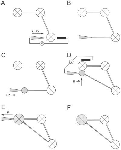
To construct topologically complex networks by electrofusion, open lipid bilayer NVNs were first formed. These type of networks are topological spheres (g = 0), having multiple surface-immobilized vesicle containers (5–50 μm in diameter) interdigitated with nanotubes (100–200 nm in diameter). The networks were made by a micropipette-assisted technique from giant unilamellar, or thin-walled, vesicles attached to multilamellar vesicles as described (12). With this method, networks can be produced with controlled nanotube length, angle between nanotube extensions, and vesicle container diameter. In brief, a tapered borosilicate-glass micropipette with an outer-tip diameter of 0.5–1 μm, back-filled with aqueous medium, and mounted onto an electroinjection system (16), was pressed against the membrane of a surface-immobilized vesicle. By applying dc-voltage pulses of field strengths between 10 and 40 V/cm and duration of 1–4 ms over the micropipette, the lipid membrane was penetrated (Fig. 1A). The micropipette was then slowly pulled out and away from the mother vesicle, forming a lipid nanotube connection between the mother liposome and the pipette tip (Fig. 1B). Aqueous medium was thereafter injected into the nanotube with a pressurized air-driven microinjector, thus forming a small satellite vesicle at the outlet of the micropipette (Fig. 1C). This newly created vesicle could then be immobilized onto the substrate surface at desired coordinates by the application of an axial force and was subsequently released from the pipette tip.
Figure 1.
Schematic sequence showing the formation of lipid nanotube-vesicle circuits. Surface-immobilized vesicles are marked with an X, and satellite vesicles that are “free” in solution are drawn as open circles. (A) The membrane of a giant vesicle is penetrated by a combination of mechanical force (F) applied from the micropipette and anodic electric pulses (+V) from a low-voltage pulse-generator (V). As a counter electrode a 5-μm carbon fiber is used. (B and C) A nanotube is created by pulling the micropipette away from the mother vesicle, and a small satellite vesicle is created at the end of the nanotube by injecting buffer solution into the nanotube orifice. (D) The satellite vesicle is positioned in close contact to another vesicle container within the network. Fusion of the vesicle containers is stimulated by application of one or several transient rectangular dc-voltage pulses and mechanical force. (E and F) The micropipette is withdrawn from the daughter vesicle. Lipid tubes adhering to the pipette tip after removal from the daughter vesicle were detached by applying one or several cathodic electric pulses.
For creation of a closed network (g = 1), the small satellite vesicle, preferably having a diameter of 4–6 μm and still adhering to the pipette tip, was positioned in close contact to another vesicle container within the network (Fig. 1D). To obtain a highly focused electrical field over the two containers, a carbon fiber microelectrode was placed adjacent to the fusion partners. Fusion of the vesicle containers was stimulated by application of one or several transient rectangular dc-voltage pulses of field strengths between 40 and 80 V/cm and duration of 1–4 ms over the micropipette. Withdrawal of the micropipette could be performed without visible signs of vesicle deformation or leakage and residual lipid tubes still adhering to the pipette tip could be removed by applying one or several cathodic dc-voltage pulses over the micropipette (Fig. 1 E and F).
As the vesicle fusion completed, the diameter of the nanotubes instantly increased from an original diameter of 100–200 nm, up to several μm in diameter for a few seconds before they regained their original diameter. Because liposome fusion is a very fast event that typically is completed in <100 ms, a very rapid change in the surface-to-volume ratio is achieved, causing an instant lowering of membrane tension in the network, and thus a lowering in surface free energy. Because the nanotube radius, rt, is governed by the lateral membrane tension, Tm, of the system according to:
 |
1 |
where kc is the bending modulus (17); the change in lateral tension explains the dramatic modulation of the nanotube diameter. Over time, however, the lowering in surface energy is balanced by vesicle adhesion and a new mechanical equilibrium will be reached (18). Consequently, the fusion procedure induced a transient instability in the system; however, the structural integrity of the network always remained intact after this perturbation. Detailed studies on the stability of these structures have not been undertaken; these structures, however, appear to be stable for several hours. Over time, the vesicle containers will spread on the substrate surface, ultimately inducing a structural collapse of a network.
The electrofusion of two vesicles is simple to perform, and several attempts can be made until fusion is achieved. In our hands single fusion attempts were close to 100% successful. For construction of complex networks, the success rate was somewhat lower. For example, we estimate that closed four container networks (g = 1) can be constructed at a success rate of ≈75% by a person skilled in the art. Experience in micromanipulation and micropipette techniques, such as microinjection, is advantageous for successful usage of these protocols. All of the membrane structures shown in this work were completed within 30 min from the start of the respective experiment, and the majority of the structures have been reproduced several times.
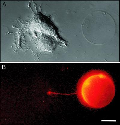
The protocol presented here is not limited to connection of vesicle containers within a network. The technique also allows incorporation of external membrane structures, such as solitary vesicles and biological cells, into a network. Fig. 2 shows an example where a surface-immobilized vesicle stained with the fluorescent dye DiO was connected through a nanotube to an adherent NG-108 cell. The capability of connecting cells and synthetic vesicles opens up interesting possibilities in integrating and probing biological functions in biohybrid networks. In particular, using methods for delivery of materials in lipid nanotubes (11, 12) exchange of materials between cells and vesicles can be controlled. For example, small cytoplasmic samples can be taken from the cell and delivered through the nanotube to a vesicle containing a reporter system in sensor applications, or cell-affecting agents can be delivered from a vesicle to a cell.
Figure 2.
Integration of biological cells. A surface-immobilized giant vesicle was connected through a nanotube to an adherent NG-108 cell by using a combination of micropipette-assisted daughter vesicle formation and electrofusion. (A) A differential interference contrast micrograph of the cell-vesicle system. (B) The corresponding fluorescence micrograph is shown and is pseudo-colored for enhanced visibility. The liposome membrane was stained with the fluorescent dye DiO (0.5 mol%). Both images are composed of a z-directional stack of 16 video frames, explaining the bent appearance of the nanotube. (Scale bar: 10 μm.)
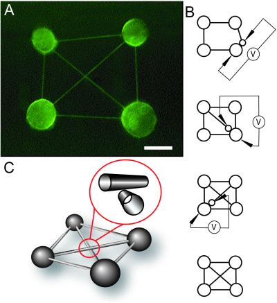
If we view surface-immobilized vesicles as vertices in a coordinate system, this method allows connection of any vertex with an edge (nanotube connection) irrespective of the vertex coordinates. Consequently, closed NVNs up to fully connected networks [n containers, and n(n-1)/2 nanotubes], the basis for Hopfield-type architectures (19), can be created. Fig. 3A shows a fluorescence micrograph of a fully connected network having four containers and six nanotubes made by using a combination of micropipette-assisted satellite vesicle formation and microelectrofusion as illustrated in Fig. 3B. This structure represents a g = 3 topology, and in principle, the generic fusion scheme presented here can be used repeatedly on a given network to produce structures of very complex geometries and higher-order topologies. Note that the crossing diagonal nanotubes lie in separate planes as illustrated in Fig. 3C, making it possible to construct overlaid nanotube network architectures. For example, in fully connected networks the maximum number of layers, NL is given by NL = nt − nc; ∞ > nc ≥ 4 (where nt is the number of nanotubes, and nc is the number of containers) which means that for a six-, seven-, and eight-container network, NL will be 9, 14, and 20, respectively.
Figure 3.
Formation of fully connected networks. (A) A fluorescence micrograph of a four-container Hopfield-type network constructed by using a combination of micropipette-assisted daughter vesicle formation and microelectrofusion. The lipid membrane is stained with the fluorescent dye DiO (0.5 mol%). (Scale bar: 10 μm.) (B) Schematic illustration of the procedure. The intersecting nanotubes in the middle of the network do not represent a nanotube four-way junction; the paths of two nanotubes are instead crossed in an overlaid fashion as illustrated in C.
Geometrical Self-Organization of Networks.
One of the most fascinating features of these continuum membrane structures is their dynamical self-organizing behavior. This feature is governed by the material properties of the fluid-state bilayer membrane. Following the ansatz of Helfrich (20, 21), the curvature energy per unit area of thin elastic shells is a quadratic function of the principal curvatures, c1, c2:
 |
2 |
where c0 is the spontaneous curvature, and kc and kc′ are the bending modulus and saddle splay modulus, respectively. The equilibrium shape of a free vesicle in solution can be found from minimizing the elastic energy of bending:
 |
3 |
In our system, vesicles are immobilized on a surface, and an energy adhesion term has to be introduced (22):
 |
4 |
where f is the effective potential of adhesion and S* is the area of surface-membrane contact. Because the membrane material located in the tubular segments of a network is trapped in a region of extreme curvature, the tubes are residing in an elastically excited state. In addition, vesicle containers in these networks are in the strong adhesion regime. Consequently, these structures are under lateral membrane tension, further stretching the tubes. Therefore, the tubular segments of a NVN are forced to connect between containers in a way describing the shortest distance to lower the surface free energy of the system.
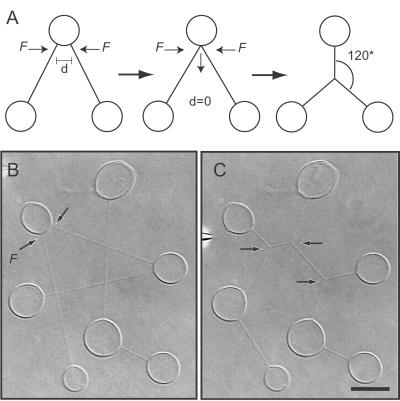
The fluidity of the membrane material allows translation of a nanotube across both nanotube and vesicle surfaces to any position in a network (11, 23). Therefore, nanotubes emanating from a common vesicle container must be separated by a distance, d, at the vesicle-nanotube interface to preserve the geometry of the system. If two nanotubes are positioned in such a way that there is no separation distance (d = 0), the tubes will coalesce and arrange themselves into the minimum pathway solution of the specific geometry set by the vertex coordinates of the connected containers. Fig. 4A shows schematically how such structures can be created from a V-shaped three-container network by forcing the nanotubes emanating from the vesicle in the central position to coalesce. As the two nanotubes merge, a three-way junction will form and move to the coordinates describing the minimum pathway. Provided that all of the nanotubes in the structure have the same tension, and thus diameter, simple geometric considerations give that the shortest way to connect three vertices is via an intersection having 120° angles.
Figure 4.
Dynamic self-organization of networks. (A) Schematic showing how nanotube three-way junctions are formed by forcing two nanotubes emanating from the central vesicle in a V-shaped sequential three-container network to coalesce. As the two nanotubes merge, a three-way nanotube junction will form and move to the coordinates describing the minimum pathway arrangement of the nanotubes. (B) Pathway minimization is stimulated in a sequential seven-container network by forcing the tubes marked with black arrows to coalesce. The system was triggered by hydrodynamical displacement of a nanotube by flushing with buffer solution from the micropipette. (C) The final configuration of the network. The system now contains nine tubular segments and three three-way junctions (black arrows), all having separation angles of 120°. (Scale bar: 5 μm.)
This self-organizing behavior can be used for increasing the complexity of the networks. Fig. 4 B and C shows an experiment where a seven-container network having a total tube length of 120 μm evolves into a lower energy configuration by geometrical rearrangement of nanotubes. The event was triggered by forcing two nanotubes emanating from a mutual vesicle container to coalesce, forming a three-way junction (Fig. 4B). As this junction moved toward its minimum pathway solution, the nanotubes connected to this junction coalesced with neighboring tubes at their respective vesicle-tube interface, thus causing a domino-like effect where new three-way junctions were formed and transported toward a lower energy configuration. When all of the junctions reached their minimum pathway configuration, the movement of junctions was terminated. The new configuration contained nine tubular segments and three three-way junctions, all having separation angles of 120°, and supported a total tube length of 85 μm as illustrated in Fig. 4C.
Nanotube-Mediated Injection of Vesicle Contents and Formation of Complex Contents-Differentiated Networks.
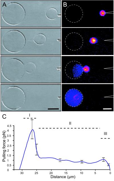
As discussed above, the membrane material located in the nanotubes is trapped in an elastically exited state and therefore acts as mechanical springs that try to pull connected containers together to lower the energy of the system. Thus, satellite vesicles that are released from the pipette tip and that are not allowed to adhere to any surface can be used for highly controlled transport and injection of finite amounts of materials into a specific vesicle container in a network. Satellite vesicles exclusively contain solution originating from the micropipette (12) and can carry volumes as small as a few femtoliters. We loaded satellite vesicles with fluorescein solution that were released from the pipette tip by application of a voltage pulse. After release, the satellite vesicle was transported and subsequently merged with the nanotube-conjugated vesicle into which it released its contents (Fig. 5 A and B). Again, this transport is driven by minimization of elastic energy stored in the membrane material.
Figure 5.
Nanotube-mediated injection of vesicle contents. (A) Series of differential interference contrast micrographs illustrating how a small satellite vesicle created by the micropipette-assisted technique is released from the tip of the micropipette by application of a voltage pulse (40 V/cm, 4 ms). When the vesicle detaches from the pipette, it is immediately pulled toward its tube-conjugated mother where the two vesicles subsequently merge. (B) Series of intensity indexed fluorescence micrographs of the tube-mediated transport and injection of a fluorescein-filled (25 μM in buffer solution) satellite vesicle. Once the vesicles are in contact, coalescence typically occurs within 100 ms. A and B are different experiments. (Scale bar: 5 μm.) (C) Graph showing the pulling force of the nanotube-vesicle system as a function of tube length (mean ± SEM, n = 6). The satellite vesicles were released from a pipette tip into solution as illustrated in A and did not adhere to the substrate surface. This transport exhibits a nonlinear behavior and is composed of three distinct phases (I–III).
If frictional forces acting on the nanotube are neglected and the lateral tension in the system is sufficiently high, the satellite vesicle will remain largely spherical, and the pulling force, F, of the system can be approximated from Stokes frictional drag past a sphere (24). As illustrated in Fig. 5C, the vesicle transport exhibited a nonlinear behavior composed of three distinct phases. Initially, when a satellite vesicle was released from the pipette tip, the system displayed an acceleration-deceleration peak, an effect most likely caused by the applied electric field used for releasing the vesicle. After this initial response, the pulling force decreased almost linearly with tube length. Before the vesicles merged, there was a distinct decrease in the measured pulling force. This last phase may be caused by alignment of the two nanotube-vesicle junctions. Typical pulling forces in the linear phase were 0.5–1 pN.
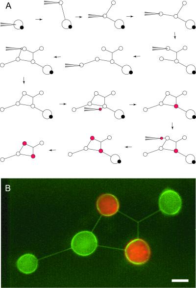
In Fig. 6, we demonstrate how a combination of micropipette-assisted network formation, microelectrofusion, and nanotube-mediated satellite vesicle transport and injection can be used for incorporating closed loops, branched nanotubes, and differentiated containers into a single NVN. The entire sequence for creating this network requires >20 different steps of which 12 are schematically illustrated in Fig. 6A. In this network, all vesicles and nanotubes were created from a single giant unilamellar-multilamellar vesicle. After the network was formed, a micropipette was loaded with 30 nm fluorescent latex beads and satellite-vesicle injection was used to deliver approximately 50 fl of latex bead solution each into two vesicle containers. As the construction of the network was completed, the nanotube connecting the giant unilamellar-multilamellar vesicle was cut by using a carbon fiber. A fluorescence image of the final network is shown in Fig. 6B.
Figure 6.
Differentiation of networks. (A) Schematic showing the procedure of creating a differentiated network having closed loops and branching nanotubes. Differentiation of the chemical composition of individual liposomes in the network was obtained by nanotube-mediated fusion of satellite vesicles containing red fluorescent 30-nm latex beads. (B) A fluorescence micrograph of the actual structure is shown. The membrane of the NVN is stained with DiO (0.5 mol%) The colors were detected by using separate channels and were overlaid by using adobe software. (Scale bar: 5 μm.)
Conclusion and Outlook
We have presented an electrofusion protocol for formation of NVNs of highly complex geometries and advanced topologies, including closed circular networks as well as fully connected networks with three-dimensional nanotube layers. In addition, we have demonstrated how the self-organizing feature of lipid membranes can be used for incorporating branching lipid nanotubes, further increasing the complexity of these networks. Finally, we show how containers within closed circular networks could be modified and differentiated independently with respect to interior contents by using a satellite vesicle transport scheme.
Networks produced by us previously (10–12) all have been topological spheres, which limit their utility for many applications. According to the methods presented here, any vertex (container) can be connected by an edge (nanotube) in a predetermined fashion. We judge this to be an important step toward creating fluid-state membrane devices with applications in nanofluidics (10), as well as model systems for studies of single-molecule behaviors (25), synchronized population behaviors of enzymes in confined spaces (26), and diffusible behaviors of biological molecules (6, 14). Moreover, cells and cell networks, as well as membrane proteins, can be reconstituted in these systems, enabling a combination of complex function with extreme spatial confinement.
Acknowledgments
The help from Dr. Volkmar Heinrich is appreciated. This work was supported by the Royal Swedish Academy of Sciences through a donation by the Wallenberg Foundation, the Swedish Natural Science Research Council, and the Swedish Foundation for Strategic Research through their Individual Grant for Advancement of Research Leaders and Biomics programs.
Abbreviations
- NVN
nanotube-vesicle network
- DiO
3,3′-dioctadecyloxacarbocyanine perchlorate
Footnotes
This paper was submitted directly (Track II) to the PNAS office.
References
- 1.Brittain S T, Schueller O J A, Wu H K, Whitesides S, Whitesides G M. J Phys Chem B. 2001;105:347–350. [Google Scholar]
- 2.McDonald J C, Duffy D C, Anderson J R, Chiu D T, Wu H K, Schueller O J A, Whitesides G M. Electrophoresis. 2000;21:27–40. doi: 10.1002/(SICI)1522-2683(20000101)21:1<27::AID-ELPS27>3.0.CO;2-C. [DOI] [PubMed] [Google Scholar]
- 3.Vaeth K M, Jackman R J, Black A J, Whitesides G M, Jensen K F. Langmuir. 2000;16:8495–8500. [Google Scholar]
- 4.Jorgenson J W, Lukacs K D. Anal Chem. 1981;53:1298–1302. [Google Scholar]
- 5.Desmet G, Baron G V. Anal Chem. 2000;72:2160–2165. doi: 10.1021/ac991254+. [DOI] [PubMed] [Google Scholar]
- 6.Chiu D T, Wilson C, Karlsson A, Danielsson A, Lundqvist A, Strömberg A, Ryttsén F, Davidson M, Nordholm S, Orwar O, Zare R N. Chem Phys. 1999;247:133–139. [Google Scholar]
- 7.Chiu D T, Pezzoli E, Wu H K, Stroock A D, Whitesides G M. Proc Natl Acad Sci USA. 2001;98:2961–2966. doi: 10.1073/pnas.061014198. [DOI] [PMC free article] [PubMed] [Google Scholar]
- 8.Culbertson C T, Jacobson S C, Ramsey J M. Anal Chem. 2000;72:5814–5819. doi: 10.1021/ac0006268. [DOI] [PubMed] [Google Scholar]
- 9.Seifert U. Adv Phys. 1997;46:16–137. [Google Scholar]
- 10.Karlsson R, Karlsson M, Karlsson A, Cans A-S, Bergenholtz J, Akerman B, Ewing A G, Voinova M, Orwar O. Langmuir. 2002;18:4186–4190. [Google Scholar]
- 11.Karlsson A, Karlsson R, Karlsson M, Cans A-S, Stromberg A, Ryttsén F, Orwar O. Nature (London) 2001;409:150–152. doi: 10.1038/35051656. [DOI] [PubMed] [Google Scholar]
- 12.Karlsson M, Sott K, Cans A-S, Karlsson A, Karlsson R, Orwar O. Langmuir. 2001;17:6754–6758. [Google Scholar]
- 13.Zimmerman U. Biochim Biophys Acta. 1982;694:227–277. doi: 10.1016/0304-4157(82)90007-7. [DOI] [PubMed] [Google Scholar]
- 14.Chiu D T, Wilson C F, Ryttsen F, Stromberg A, Farre C, Karlsson A, Nordholm S, Gaggar A, Modi B P, Moscho A, et al. Science. 1999;283:1892–1895. doi: 10.1126/science.283.5409.1892. [DOI] [PubMed] [Google Scholar]
- 15.Criado M, Keller B U. FEBS Lett. 1987;224:172–176. doi: 10.1016/0014-5793(87)80442-8. [DOI] [PubMed] [Google Scholar]
- 16.Karlsson M, Nolkrantz K, Davidson M J, Stromberg A, Ryttsen F, Akerman B, Orwar O. Anal Chem. 2000;72:5857–5862. doi: 10.1021/ac0003246. [DOI] [PubMed] [Google Scholar]
- 17.Evans E, Yeung A. Chem Phys Lipids. 1994;73:39–56. [Google Scholar]
- 18.Evans E A. Biophys J. 1980;31:425–432. doi: 10.1016/S0006-3495(80)85069-7. [DOI] [PMC free article] [PubMed] [Google Scholar]
- 19.Hertz J A, Palmer R G, Krogh A S. Introduction to the Theory of Neural Computation. Reading, MA: Addison–Wesley; 1991. [Google Scholar]
- 20.Helfrich W. Z Naturforsch. 1973;28:693–703. doi: 10.1515/znc-1973-11-1209. [DOI] [PubMed] [Google Scholar]
- 21.Deuling H J, Helfrich W. J Phys (France) 1976;37:1335–1345. [Google Scholar]
- 22.Seifert U, Lipowsky R. Phys Rev A At Mol Opt Phys. 1990;42:4768–4771. doi: 10.1103/physreva.42.4768. [DOI] [PubMed] [Google Scholar]
- 23.Evans E, Bowman H, Leung A, Needham D, Tirrell D. Science. 1996;273:933–935. doi: 10.1126/science.273.5277.933. [DOI] [PubMed] [Google Scholar]
- 24.Waugh R E. Biophys J. 1982;38:19–27. doi: 10.1016/S0006-3495(82)84526-8. [DOI] [PMC free article] [PubMed] [Google Scholar]
- 25.Xie X S, Trautman J K. Annu Rev Phys Chem. 1998;49:441–480. doi: 10.1146/annurev.physchem.49.1.441. [DOI] [PubMed] [Google Scholar]
- 26.Stange P, Zanette D, Mikhailov A, Hess B. Biophys Chem. 1999;79:233–247. doi: 10.1016/s0301-4622(99)00057-5. [DOI] [PubMed] [Google Scholar]


