

Abstract
Electron cryomicroscopy of rotor complexes of the Salmonella typhimurium flagellar motor, overproduced in a nonmotile Escherichia coli host, has revealed a variation in subunit symmetry of the cytoplasmic ring (C ring) module. C rings with subunit symmetries ranging from 31 to 38 were found. They formed a Gaussian distribution around a mean between 34 and 35, a similar number to that determined for native C rings. C-ring diameter scaled with the number of subunits, indicating that the elliptical-shaped subunits maintained constant intersubunit spacing. Taken together with evidence that the M ring does not correspondingly increase in size, this finding indicates that rotor assembly does not require strict stoichiometric interactions between the M- and C-ring subunits. Implications for motor function are discussed.
INTRODUCTION
The flagellar basal body of the enteric bacterium Salmonella typhimurium houses machinery for the switching and energization of flagellar rotation as well as export of flagellar proteins. About 30 proteins are required for its assembly. More than half of these are known to be structural components of the bacterial flagellum (Namba, 2001; Macnab, 1999). Three proteins of the flagellar basal body, FliG, FliM, and FliN, are necessary for motor switching and energization (Yamaguchi et al., 1986; Zhao et al., 1996). These form a cytoplasmic complex, which serves both as the switch complex and the rotor of the flagellar motor.
Recently, we overexpressed FliG, FliM, and FliN with FliF in a nonmotile E. coli host (Lux et al., 2000). FliF forms the transmembrane MS ring complex and is the base to which the motor-switch proteins bind (Kubori et al., 1997). The presence of FliG results in a thickening of the M ring (Francis et al., 1992). FliM and FliN, perhaps together with domains from FliG, generate an additional ring called the C ring for its location in the cytoplasm. The co-overexpression of all four proteins led to overproduction of membrane-associated, partial basal body structures. A preliminary examination in negative stain showed that the isolated MSC ring complexes appeared indistinguishable from those of native basal bodies.
Here, we have examined the M, S, and C rings, henceforth termed rotor particles, in vitreous ice by electron cryomicroscopy.
MATERIALS AND METHODS
Sample preparation
BL21(λDE3) transformed with plasmids pKLR1 and pKOT179 were grown in Luria broth. pKLR1 and pKOT179 are pSU18- and pET3-based plasmids, respectively. Protein expression was induced by isopropyl-β-thio galactoside addition inasmuch as pKLR1 expresses FliF, FliG and pKOT179 FliM, FliN upon induction of T7 polymerase from the BL21(λDE3) chromosome under Lac promoter control (Lux et al., 2000). Overproduced rotor particles were purified as previously described (Lux et al., 2000). In brief, cells from a 1-liter late exponential culture were solubilized by incubation with 1% Triton X-100/EDTA/lysozyme for 4 h on ice. The supernatant, left after getting rid of unlysed cell debris by low-speed centrifugation, was spun down (60,000g, 1 h) to pellet the rotor particles. The pellet was resuspended in 1 ml of buffer and mechanically sheared by passage back and forth between 26-gauge needle, 3-ml capacity syringes. The sheared sample was then centrifuged again to pellet the rotor particles, which were resuspended in 0.2 ml of buffer (0.1% Triton X-100, 10 mM Tris, 5 mM EDTA, 0.05% sodium azide, pH 8.0).
Electron cryomicroscopy
Frozen-hydrated specimens were prepared by diluting purified switch complexes 20-fold with excess buffer that reduced the Triton X-100 concentration to 0.005%. 5 μl were applied to 300-mesh copper grids that had been coated with Holey carbon films (Toyoshima, 1989) and glow-discharged in air. After blotting excess solution from the carbon side of the grids, they were immediately vitrified in ethane slush (Lepault and Dubochet, 1986). The frozen grids were stored in liquid nitrogen. Images were obtained with a Philips (Eindhoven, Holland) CM200 FEG electron microscope equipped with an Oxford (Oxford, UK) CT-3500 specimen holder, which maintained the specimen temperature at −180°C. They were recorded on Kodak SO163 film at 2.0–3.0 μm underfocus at 50,000× magnification (a calibrated magnification of 51,300×), with doses of 10–16 electrons/Å2. Possible changes in magnification due to eucentricity error were estimated to be ±1.4%.
Image analysis
Images of rotor particles suspended over the carbon film were digitized with a Zeiss Scan (Carl Zeiss GMBH, Oberkochen, Germany) at 42-μm intervals (corresponding to 8.2 Å per pixel). The circular rings seen in en-face views were approximately centered with the aid of an annular mask (inner radius, 22 pixels; outer radius, 30 pixels). The particle center was refined around a 5 × 5 pixel grid to determine the best choice of origin (Crowther and Amos, 1971). At each of the 25 positions, an angular cross-correlation function was generated. To do so, the outer, C ring was isolated from the rest of the image by an annular mask, and the image was rotated by 1° angular increments. At each angular increment, a cross-correlation coefficient was computed between the original and rotated images. The resulting cross-correlation function was generated over 0–360° and allowed assessment of the subunit symmetry as done by Thomas et al. (1999). To avoid ambiguities, a power spectrum of the cross-correlation function was computed to determine its periodicity.
Once the best origin was determined, the rotor particle diameter was measured by determining the average density as a function of radial distance. The C ring was visible as a peak of density in this average. The outer diameter was determined from the peak maximum, which was determined by a spline fit of the peak.
Image averages for the different subunit groups were obtained as follows. First, an average for each group, with the particles centered as outlined above, was obtained. The appropriate rotational symmetry was then imposed on each average and these symmetry-reinforced averages used for initial alignment. Thereafter, the image averages generated from an alignment cycle were used as reference images for the subsequent alignment. Typically the average and variance maps converged after six to eight alignment cycles. We checked that symmetry reinforcement did not bias the result, by imposing symmetries that were offset by ±1 from the group symmetry. Nevertheless, in both cases the initial alignment still yielded an average map with the true group rotational symmetry. However, the corresponding variance maps were noisier and the alignment took more cycles to converge. Operations available in the single particle image processing package, SPIDER (Health Research, Albany, NY), were used for all image analysis procedures described above.
RESULTS
Rotor particles present predominantly en-face views
Holey carbon films were used in an attempt to image the rotor particles over holes in the carbon support. However, the rotor particles preferentially associated with the carbon film and only rarely remained in the holes. Nonetheless, the rotor particles were qualitatively similar and appeared well preserved whether found in holes or on the carbon support.
En-face views of the rotor particles predominated (Fig. 1) presumably because this orientation maximizes the interaction of the rotor with the carbon support (Boisset et al., 1990). Variations from the ideal en-face view resulted from particle deformation, nonplanarity of the carbon film, and interactions of the particles with both the carbon film and the air–water interface (Wagenknecht et al., 1990; Schmutz et al., 1994). The prevalence of en-face views is in marked contrast to that for hook basal body complexes for which the particles are predominantly found in a side-on orientation (see, for example, Fig. 4 of Khan et al., 1998). Therefore, the overproduced rotor particles offered an opportunity to characterize the en-face orientation, heretofore rarely observed (Thomas et al., 1999).
FIGURE 1.
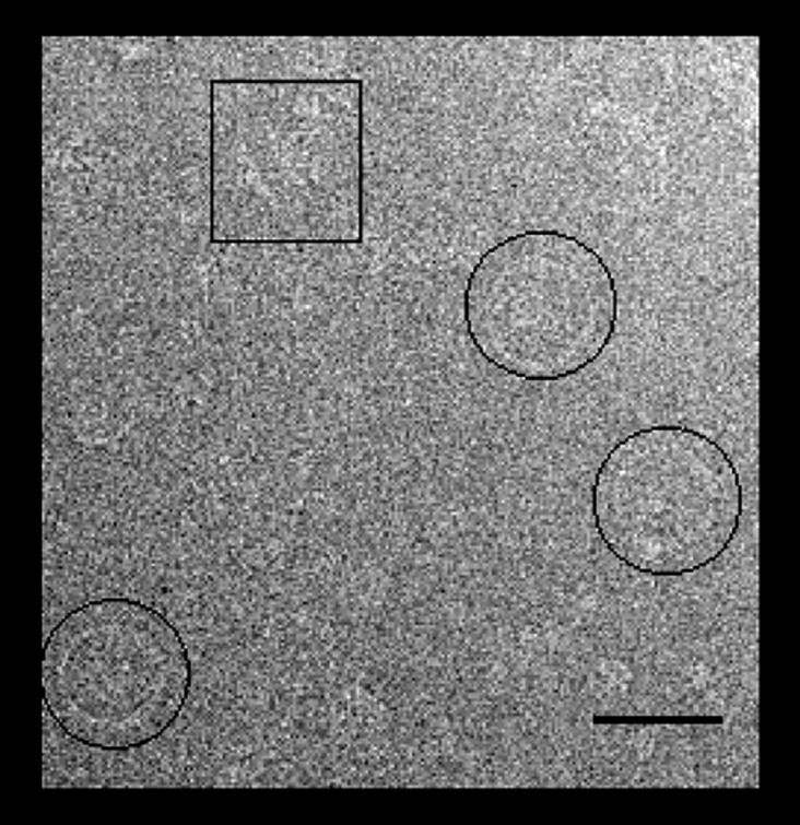
Low magnification view of a field of rotor particles over carbon. Particles in en-face orientation (circled) predominate. Side-on views (boxed) were rare. Bar, 50 nm.
FIGURE 4.

C-ring subunit symmetry changes with particle size. (Left) Different sized particles. (Right) Corresponding composite power spectra. Each composite is composed of 25 superimposed spectra, one for each of the 25 grid positions used for centration. The increase in subunit symmetry with particle size cannot be due to centration error, inasmuch as peak position within each composite spectrum does not change by greater than one.
Variation in rotor diameter results from a variation in the number of subunits
Images of side-on views (Fig. 2) confirmed our earlier impression that the morphology of the overproduced rotors was qualitatively similar to that seen for native rotors (Lux et al., 2000). As for native rotors, variations in C-ring diameter were apparent. To eliminate the possibility that these variations could be due to C-ring distortion such as flattening, we used only en-face views where such distortion could be assessed. Fig. 3 as described in the Materials and Methods section outlines our strategy for centering each C ring, measuring its diameter, and determining its rotational symmetry. For well-preserved particles, the location of the symmetry axis could be determined within 1 pixel. The use of peak fitting to locate the maximum helped mitigate effects of noise in the cross-correlation plots (Fig. 3 C). An error of one pixel in the location of the axis changed the estimate of the rotational symmetry by one. Differences in the symmetries of the three particles shown in Fig. 4 clearly cannot be accounted for by errors in the positioning of the axis of symmetry.
FIGURE 2.

Side-on views of two rotor particles in ice. These images compare well with side-on views of native rotor particles shown by Thomas et al. (1999, 2001). Vertical bars mark the extent of the C rings. Differences in C-ring diameter between the two particles are apparent. Horizontal bar, 25 nm.
FIGURE 3.
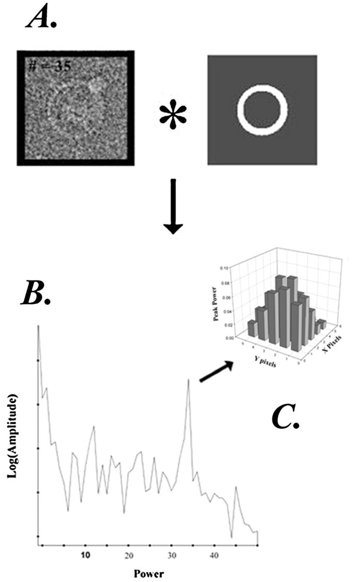
C-ring subunit symmetry determination for single rotor particles. Each particle was centered with the aid of an annular mask (A). The particle was centered by moving the origin on a 5 × 5 grid, with one pixel separation between grid positions. For each position, the mask was used to compute the rotational cross-correlation function, as described (see Materials and Methods), with the frequency spectrum (B) being obtained by Fourier transformation of the correlation function. (C) Change in amplitude of the peak frequency spectrum as a function of grid position.
The distribution of rotors with different subunit symmetries is Gaussian
Of over 1000 particles imaged, more than 95% were in the en-face orientation. We chose 590 en-face views for further analysis, based on their power spectra. Of these, 185 particles gave power spectra with prominent maxima from which we could determine the rotational symmetry of the C ring. A Gaussian distribution of C-ring subunit symmetries was obtained for this particle set with a mean of 34.5 and ±4 subunit SD (Fig. 5). This mean number of subunits per C ring is the same as that found for native rotors (Thomas et al., 1999).
FIGURE 5.

Histogram of the number rotor particles as a function of C-ring subunit periodicity. A periodicity of 34–35 subunits was most common. The distribution was well fit by a Gaussian (continuous line). The SD was ±1.4 subunits.
Average images reveal a subunit with an elliptical profile
We constructed average image maps from the 185-particle-image dataset for the more populous 32–36 subunit groups. Individual images were translationally and rotationally aligned as detailed in Materials and Methods. Over a third of the original image set was rejected for the image averages. The rejected set included images that were visibly elliptical or deformed as well as images for which an unique symmetry could not be cleanly determined from the peak in the C-ring power spectrum. Fig. 6 A shows the plain and rotational symmetry reinforced average maps for the 34 subunit C-ring group, as well as the corresponding variance map. The spectral purity of the average map was assessed by plots of correlation function vs. frequency spectrum (Fig. 6 B).
FIGURE 6.

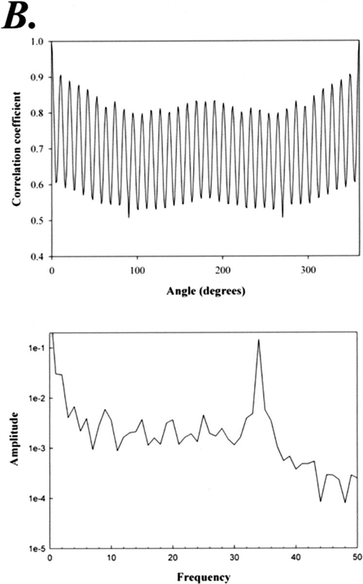
(A) Average, symmetry-reinforced average, and variance maps of the 34 subunit C-ring rotors (29 images). (B) Cross-correlation function and the resulting power spectrum of the average map. The SD of diameter for particles within this group was ±0.7 nm (i.e., <1 pixel), or 1.7%.
The intersubunit distance is constant
Averaged rings with more subunits had proportionately larger diameters, showing that there was good correlation between C-ring diameter and subunit symmetry (Fig. 7). The plot of diameter vs. subunit number showed that intersubunit spacing remained invariant whereas diameter changed by over 11% upon progression from 32 to 36 subunit rings (Fig. 8 A). Its slope provided a measure of the intersubunit spacing, which was 3.9 nm. The subunit spacing measured by Thomas et al. (1999) for native rotor particles was also 3.9 nm.
FIGURE 7.

Symmetry-reinforced, image average maps. The maps are comprised of 9, 12, 29, 38, and 18 particles for the 32, 33, 34, 35, and 36 subunit groups respectively. A Gaussian distribution of subunit symmetries is maintained for this more select dataset. The inner diameter of the 32 subunit C ring, indicated by the red bar, is superimposed on the 34 and 36 subunit C rings to show the progressive increase in diameter with subunit number.
FIGURE 8.
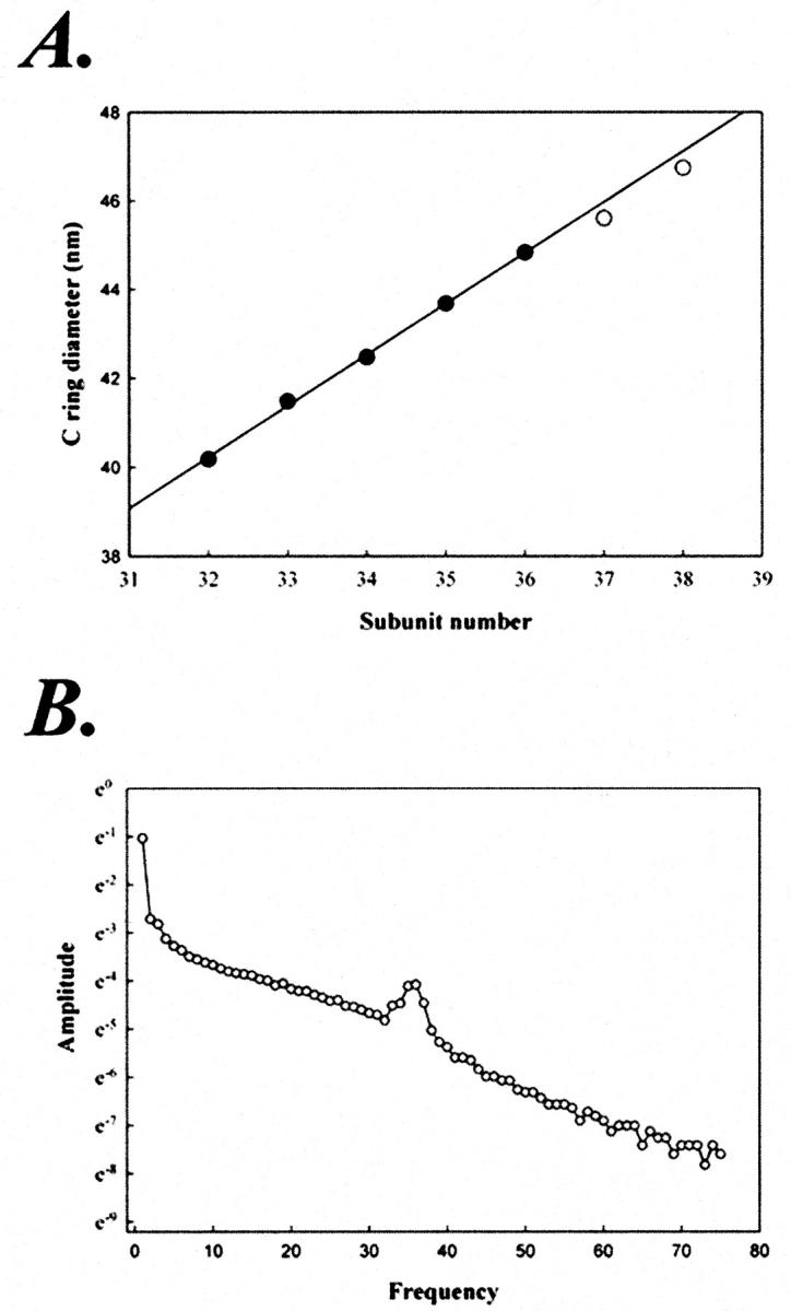
(A) Evidence for constant intersubunit distance. Diameter of the symmetry-reinforced image averages (closed circles) were plotted as a function of C-ring subunit number. The best-fit line, although constrained to pass through the origin, was imperceptibly affected by the constraint. The regression coefficient is 0.9868 and 0.9866 with and without this constraint, respectively. Its slope yielded an intersubunit spacing of 3.9 nm. Rotor particles with 37 (n = 1) and 38 (n = 3) were also found. The mean diameter values for these are also included (open circles), but were not used for the fit. The mean SD of particle diameter within a symmetry group was ±1.9%. (B) Averaged power spectrum for the 106 particles used to construct the image averages.
The incremental increase in diameter per subunit was 1.24 nm (2.9% for N = 34 subunits). The SD in diameter within a subunit group was 0.8 nm (1.9% of the diameter). Factors that contribute to such dispersion include magnification differences due to deviation from eucentricity (Bijlholt et al., 1982), differences in defocus between micrographs (Typke et al., 1992), and variation in composition, conformation, and orientation of the rotor particles. Even though particles with gross deformation and nonideal orientation (deviation from a perfect en-face view) were excluded, the 0.8-nm residual error is likely to be predominantly comprised of the presence of these defects in the remaining particles, albeit to more subtle extent. This error of 0.8 nm is less than the change in diameter of 3.9 nm/π = 1.24 nm due to the change of one in subunit number.
Periodicities in the M ring were not detected
The image averages (Fig. 7) were computed from images aligned based on their C rings. As such, they would reveal the symmetry of the M ring, which lies inside the C ring, only if the two have the same symmetry. No such periodicities in the M ring were seen. Reference-free (Penczek et al., 1996) as well as 26 symmetry-reinforced, reference-based alignments, using a circular mask to exclude the C ring from the internal parts of the rotor particles, were also not successful in revealing periodicity in the M ring. In addition, we obtained rotational power spectra for all 106 particles used for the image averages employing a circular mask that included the complete rotor particles. The power spectra were summed and averaged. As expected, the peak for the C-ring rotational symmetry is prominent, but smeared out over the 32–36 periodicities in the average power spectrum. There is an absence of subsidiary peaks (Fig. 8 B).
The C ring is a high-contrast feature in the en-face view. This is because it has approximately five times greater mass-per-unit projected area than the internal MS ring. To calculate the mass-per-unit projected area, we used the stoichiometries (Zhao et al., 1996) and masses of the component proteins and the dimensions of the rings (Francis et al., 1994). We assumed that FliM, FliN and half of FliG contribute to the C ring and FliF and half of FliG contribute to the M ring. Determination of the rotational symmetries of the other components will require higher resolution images, larger sample size, and/or more sophisticated methods for symmetry determination (Kocsis et al., 1995).
DISCUSSION
The cytoplasmic ring (C ring) is the most distal of several coaxial rings that make up the flagellar basal body. It is necessary for torque generation and switching (Yamaguchi et al., 1986; Zhao et al., 1996). The C ring corresponds physically to the switch complex (Lux et al., 2000) and sits at the base of the MS ring. FliM and FliN are part of the C ring (Francis et al., 1994), but their assembly into a functional C ring requires the MS ring. FliF makes up the MS ring (Ueno et al., 1994). FliG is localized to the face of the MS ring (Thomas et al., 1999). An interaction between FliG and FliM connects the C ring to the M ring (Thomas et al., 2001). Thus, minimal MSC-ring complexes, which should retain rotor function but not flagellar protein export, can be formed by overexpression of these four proteins (Lux et al., 2000).
The copy number of FliM corresponds physically to the rotational symmetry of the C ring (Thomas et al., 1999), and the stoichiometry of FliM/FliN is ∼1:3 (Zhao et al., 1996; Kihara et al., 1996). The most striking feature of the MSC ring en-face view is a series of rotationally equivalent subunits at the outermost C ring. These subunits correspond to FliM and FliN inasmuch as the C ring is formed upon overexpression of FliM and FliN together with FliF and FliG, but not upon overexpression of FliF and FliG alone (Lux et al., 2000).
In this report, the overproduced flagellar rotor complexes have been characterized by electron cryomicroscopy. More than 1000 en-face images have been recorded, and the subunit symmetry and diameter of over 100 have been analyzed. Despite the relatively small number of rotor particles contributing to the image averages, they reveal important features of these complexes.
Our main finding is that the overproduced rotor C rings possess variable rotational symmetry but constant intersubunit spacing. This result extends initial evidence from native rotor C rings. In the four en-face images of native C rings published thus far (Thomas et al., 1999; Khan et al., 1998), two particles possess a subunit symmetry of 34 and two possess a symmetry of 33. In the light of the more extensive variation documented here, it will be important to determine whether similar variation exists in the native case or is constrained due to, for example, proteins of the flagellar export apparatus that are absent in the overproduced rotors. Overproduced rotor complexes with 34 or 35 subunit C rings are the most populous groups. The increase in diameter with subunit number converts to an intersubunit spacing of 3.9 nm and an optimal intersubunit angle of 10.4° ± 0.5°.
Functionality of the rotor complexes in terms of binding the response regulator CheY has been shown (Khan et al., 2000). The binding stoichiometry of activated CheY to overproduced rotor complexes was measured to be 57 ± 23. This suggests that all rotors within the overproduced population can bind CheY, and that CheY binds to rotors in a stoichiometric complex with C-ring subunits. If CheY only bound to rotors with 34 subunits, the binding stoichiometry per C ring would be less than 34:1, in contrast with observation.
Subunit number variations have been revealed in a number of circular and helical macromolecular assemblies that have been analyzed by electron microscopy thus far. The number of protofilaments present in microtubules grown in vitro depends upon parameters such as pH and ionic strength (Dias and Milligan, 1999). Bacteriophage T7 portal protein connector complexes exist as a mixed population of 12- and 13-subunit rings (Kocsis et al., 1995). The expected 7% difference in diameter between rings with 12- vs. 13-fold symmetry was not observed, but this may have been obscured by variation induced by stain and drying artifacts, rather than changes in subunit morphology. An electron cryomicroscopy study of analogous SPP1 portal protein complexes documented a change in curvature upon ring closure consistent with inextensible subunits (Van Heel et al., 1996). In both examples, the variations are thought to play important roles in regulation of assembly.
Variable C-ring subunit stoichiometry in the overproduced rotors implies either that this variation is controlled during assembly of native rotors or that this variation does not affect the torque generation mechanism. We do not presently know whether C rings with different subunit symmetries are functional and have comparable efficiency. We do know, however, that C rings with 31 subunits found in a mutant strain expressing a truncated FliF–FliG fusion protein were functional (Thomas et al., 1999, 2001), although the motility of this mutant strain was impaired (Kihara et al., 1996). There is no way of knowing whether the impairment is due to the change in subunit number or to the large conformational changes in the rotor.
If C rings with different subunit symmetries are effective in energizing rotation this will have important implications for the mechanism, analogous to the ongoing debate regarding the role of variable C-ring symmetry in the F0F1 ATP synthase (Jiang et al., 2001). In particular, it would argue against models that rely on a strict stoichiometric relationship between rotor and switch components (Blair, 1990). As for other rotary motors (Stock et al., 1999; Smith et al., 2001), torque generation has been proposed to involve symmetry mismatch. Specifically, this mismatch has been proposed to be between the internal M and external C rings (Thomas et al., 1999). This and analogous mechanisms need to allow for variable mismatch inasmuch as there is no evidence for matching M-ring subunit variation. Indeed, the two side-on views in Fig. 2 suggest that the diameter of the M ring does not increase in correspondence with that of the C ring, consistent with images of native rotors shown by Thomas et al. (1999). The strict conservation of C-ring intersubunit spacing implies that step size rather than the extent of mismatch is the critical invariant parameter for the energy-coupling mechanism. Perhaps variable mismatch provides a facile means for adjusting the power output of flagellar motors in response to environmental cues. In any case, extended three-dimensional structural analysis of overproduced rotor particles should be able to build on these observations and map the structural changes in subunit shape and tilt that accompany the association of CheY with the rotor complex.
Acknowledgments
We thank Dr. David Stokes and Dr. William Rice for helpful discussions, Dr. Renate Lux and Dr. Niladri Kar for assistance in the early stages of this work, and Dr. Michael Lewis for technical support in the electron microscopy facility at the Skirball Institute of Biomolecular Medicine, New York University School of Medicine.
Supported by grant SDG 9930278T from the American Heart Association to H.S.Y., and grants GM35433 and GM36936, from the National Institutes of Health, to D.J.D. and S.K., respectively.
Howard S. Young’s present address is University of Alberta, Dept. of Biochemistry, Medical Sciences Building 327, Edmonton, Alberta Canada T6G 2H7.
References
- Blair, D. F. 1990. The bacterial flagellar rotary motor. Sem. Cell Biol. 1:75–85. [PubMed] [Google Scholar]
- Bijlholt, M. M., M. G. van Heel, and E. F. van Bruggen. 1982. Comparison of 4-×-6–meric hemocyanins from three different arthropods using computer alignment and correspondence analysis. J. Mol. Biol. 161:139–153. [DOI] [PubMed] [Google Scholar]
- Boisset, N., J.-C. Taveau, and J. N. Lamy. 1990. An approach to the architecture of Scutigera coeleoptara haemocyanin by electron microscopy and image processing. Biol. Cell. 68:73–84. [Google Scholar]
- Crowther, R. A., and L. A. Amos. 1971. Harmonic analysis of electron microscope images with rotational symmetry. J. Mol. Biol. 60:123–130. [DOI] [PubMed] [Google Scholar]
- Dias, D. P., and R. A. Milligan. 1999. Motor protein decoration of microtubules grown in high salt conditions reveals the presence of mixed lattices. J. Mol. Biol. 287:287–292. [DOI] [PubMed] [Google Scholar]
- Francis, N. R., V. M. Irikura, S. Yamaguchi, D. J. DeRosier, and R. M. Macnab. 1992. Localization of the Salmonella typhimurium flagellar switch protein FliG to the cytoplasmic M-ring face of the basal body. Proc. Natl. Acad. Sci. USA. 89:6304–6308. [DOI] [PMC free article] [PubMed] [Google Scholar]
- Francis, N. R., G. E. Sosinsky, D. Thomas, and D. J. De Rosier. 1994. Isolation, characterization and structure of bacterial flagellar motors containing the switch complex. J. Mol. Biol. 235:1261–1270. [DOI] [PubMed] [Google Scholar]
- Jiang, W., J. Hermolin, and R. H. Fillingame. 2001. The preferred stoichiometry of c-subunits in the rotary motor sector of Escherichia coli ATP synthase is 10. Proc. Natl. Acad. Sci. USA. 95:4966–4971. [DOI] [PMC free article] [PubMed] [Google Scholar]
- Khan, S., R. Zhao, and T. S. Reese. 1998. Architectural features of the Salmonella typhimurium flagellar motor switch revealed by disrupted C-rings. J. Struct. Biol. 122:311–319. [DOI] [PubMed] [Google Scholar]
- Khan, S., D. Pierce, and R. D. Vale. 2000. Interactions of the chemotaxis signal protein CheY with bacterial flagellar motors visualized by evanescent wave microscopy. Curr. Biol. 10:927–930. [DOI] [PubMed] [Google Scholar]
- Kihara, M., N. R. Francis, D. J. DeRosier, and R. M. Macnab. 1996. Analysis of a FliM-FliN flagellar switch fusion mutant of Salmonella typhimurium. J. Bacteriol. 178:4582–4589. [DOI] [PMC free article] [PubMed] [Google Scholar]
- Kocsis, E., M. E. Corritelli, B. L. Trus, and A. C. Steven. 1995. Improved methods for determination of rotational symmetries in macromolecules. Ultramicroscopy. 60:219–228. [DOI] [PubMed] [Google Scholar]
- Kubori, T., S. Yamaguchi, and S. Aizawa. 1997. Assembly of the switch complex onto the MS ring complex of Salmonella typhimurium does not require any other flagellar proteins. J. Bacteriol. 179:813–817. [DOI] [PMC free article] [PubMed] [Google Scholar]
- Lepault, J., and J. Dubochet. 1986. Electron microscopy of frozen hydrated specimens: preparation and characteristics. Methods Enzymol. 127:719–730. [DOI] [PubMed] [Google Scholar]
- Lux, R., N. Kar, and S. Khan. 2000. Overproduced S. typhimurium flagellar motor switch complexes. J. Mol. Biol. 298:577–584. [DOI] [PubMed] [Google Scholar]
- Macnab, R. M. 1999. The bacterial flagellum: reversible rotary propeller and type III export apparatus. J. Bacteriol. 181:7149–7153. [DOI] [PMC free article] [PubMed] [Google Scholar]
- Namba, K. 2001. Roles of partly unfolded conformations in macromolecular self-assembly. Genes Cells. 6:1–12. [DOI] [PubMed] [Google Scholar]
- Penczek, P. A., J. Zhu, and J. Frank. 1996. A common-lines based method for determining orientations for N > 3 particle projections simultaneously. Ultramicroscopy. 63:205–218. [DOI] [PubMed] [Google Scholar]
- Schmutz, M. F., J. Lang, S. Graff, and A. Brisson. 1994. Defects on planarity of carbon films supported on electron microscope grids revealed by reflected light microscopy. J. Struct. Biol. 112:252–258. [Google Scholar]
- Smith, D. E., S. J. Tans, S. B. Smith, S. Grimes, D. L. Anderson, and C. Bustamante. 2001. The bacteriophage straight phi29 portal motor can package DNA against a large internal force. Nature. 413:748–752. [DOI] [PubMed] [Google Scholar]
- Stock, D., A. G. W. Leslie, and J. E. Walker. 1999. Molecular architecture of the rotary motor in ATP synthase. Science. 286:1700–1705. [DOI] [PubMed] [Google Scholar]
- Thomas, D. R., D. J. Morgan, and D. J. DeRosier. 1999. Rotational symmetry of the C ring and a mechanism for the flagellar rotary motor. Proc. Natl. Acad. Sci. USA. 96:10134–10139. [DOI] [PMC free article] [PubMed] [Google Scholar]
- Thomas, D. R., D. J. Morgan, and D. J. DeRosier. 2001. Structures of bacterial flagellar motors from two FliF-FliG fusion mutants. J. Bacteriol. 183:6404–6412. [DOI] [PMC free article] [PubMed] [Google Scholar]
- Toyoshima, C. 1989. On the use of Holey grids in electron crystallography. Ultramicroscopy. 30:439–444. [Google Scholar]
- Typke, D., R. Hegerl, and J. Kleinz. 1992. Image restoration for biological objects using external TEM control and electronic image recording. Ultramicroscopy. 46:157–173. [Google Scholar]
- Ueno, T., K. Oosawa, and S.-I. Aizawa. 1994. Domain structures of the MS ring component protein (FliF) of the flagellar basal body of Salmonella typhimurium. J. Mol. Biol. 236:546–555. [DOI] [PubMed] [Google Scholar]
- Van Heel, M., E. V. Orlova, P. Dube, and P. Tavares. 1996. Intrinsic versus imposed curvature in cyclic oligomers: the portal protein of bacteriophage SPP1. EMBO J. 15:4785–4788. [PMC free article] [PubMed] [Google Scholar]
- Wagenknecht, T., R. Grassucci, and D. Schaak. 1990. Cryoelectron microscopy of frozen-hydrated α-ketoacid dehydrogenase complexes from Escherichia coli. J. Biol. Chem. 265:22402–22408. [PubMed] [Google Scholar]
- Yamaguchi, S., H. Fujita, A. Ishihara, S. Aizawa, and R. M. Macnab. 1986. Subdivision of flagellar genes of Salmonella typhimurium into regions responsible for assembly, rotation, and switching. J. Bacteriol. 166:187–193. [DOI] [PMC free article] [PubMed] [Google Scholar]
- Zhao, R., N. Pathak, H. Jaffe, T. S. Reese, and S. Khan. 1996. FliN is a major structural protein of the C-ring in the Salmonella typhimurium flagellar basal body. J. Mol. Biol. 261:195–208. [DOI] [PubMed] [Google Scholar]