

Abstract
Complexes of proteins with small ligands are of utmost importance in biochemistry, and therefore equilibria, formation, and decay have been investigated extensively by means of biochemical and biophysical methods. Theoretical studies of the molecular dynamics of such systems in solution are restricted to 10 ns, i.e., to fast processes. Only recently new theoretical methods have been developed not to observe the process in real time, but to explore its pathway(s) through the energy landscape. From the profiles of free energy, equilibrium and kinetic quantities can be determined using transition-state theory. This study is dedicated to the pharmacologically relevant insulin-phenol complex. The distance of the center of mass chosen as a reaction coordinate allows a reasonable description over most of the pathway. The analysis is facilitated by analytical expressions we recently derived for distance-type reaction coordinates. Only the sudden onset of rotations at the very release of the ligand cannot be parameterized by a distance. They obviously require a particular treatment. Like a preliminary study on a peptide, the present case emphasizes the contribution of internal friction inside a protein, which can be computed from simulation data. The calculated equilibrium constant and the friction-corrected rates agree well with experimental data.
INTRODUCTION
In the present report, a novel approach is described to study protein-ligand binding and unbinding on the basis of molecular dynamics (MD) simulations with respect to the energy and geometry changes connected with the process. As a model system, the 2Zn insulin hexamer was chosen with phenol as a ligand. Phenol and other phenolic compounds were traditionally used as bacteriostatic preservatives in pharmaceutical insulin preparations long before it became known that they stabilize the structure of the insulin molecule (Wollmer et al., 1987) and reduce its chemical reactivity (Brange and Langkjaer, 1992). The protracted activity of phenolic complexes and its dependence on details of engineered insulin were the subject of a recent study (Berchtold and Hilgenfeld, 1999).
2Zn insulin hexamers exist in one of three structural states, all defined by x-ray analysis (Baker et al.,1988; Bentley et al., 1976; Derewenda et al., 1989), that in solution are related by dynamic equilibria: T6 ↔ T3R3 ↔ R6. In T-state subunits, the conformation of the N-terminal B-chain (residues B1-B8) is extended, whereas in R-state subunits it is helical. The T ↔ R transition is undergone trimerwise in two steps. Mixed trimers do not form for sterical reasons. Normally T-sided, the equilibria are R-shifted by two different kinds of ligands. With small, especially inorganic anions that are coordinated to the Zn ions on the threefold axis, only half-transition to the T3R3 state occurs. Phenolic ligands, on the other hand, are accommodated, one at each interface between any of the subunits in a trimer (Fig. 1). Depending on the molar excess of phenol offered, transition continues to the R6 state. Interestingly, the phenol-binding sites do not exist in T3 trimers. Therefore, transition occurs independently of and before ligand binding, which only arrests trimers in the R3 state. Binding of phenol to one site extends the lifetime of the other two in the trimer. The hexamer thus behaves as a dimer of positively cooperative trimers that are related by negative cooperativity.
FIGURE 1.

R6 hexamer with six phenol molecules (blue) as seen along the threefold symmetry axis running through the two chloride and two zinc ions (red). The upper three dimeric insulin molecules are shown in orange. The only side chains shown are those of the zinc-coordinating histidines B10.
This implies that the binding sites should be accessible for phenol to bind and to keep the conformation in the R-state, on the one hand, as well as to unbind and to allow the conformation to switch back to the T-state, on the other. The x-ray structure of R6 insulin given in Fig. 2, however, shows that the phenol molecules are partially buried (Derewenda et al., 1989) and, hence, seem to be trapped in their hydrophobic binding pockets (Fig. 3). This suggests that ligand binding and release could be correlated with subunit dissociation and reassociation of the hexamer. However, the slow amide proton exchange (Jacoby et al., 1996a) and fluorescence resonance energy exchange data (Hassiepen et al., 1999) proved that the lifetime of the hexamers is some orders of magnitude longer than that for bound phenol. It hence seems obvious that ligand binding and release do not require the hexamer to dissociate into subunits, but can be achieved by rather local fluctuations of one or a few “gatekeeper” residues (Jacoby et al., 1996a). According to all the results of kinetic experiments, the dissociation is also much faster than the T ↔ R transition (Karatas et al., 1991; Birnbaum et al., 1997) and therefore must occur within the intact R6 hexamer. Because information on the kinetics of phenol (un)binding is not available, experimental studies can only provide an upper limit of the phenol lifetime in the hexamer, which according to its NMR chemical shifts is less than 10 ms (Roy et al., 1989). So far rates of ligand (un)binding could only be determined from kinetic measurements (Bloom et al., 1997) made with 2,6- and 2,7-dihydroxynaphtalene as ligands that yielded lifetimes of the bound complex between 2 and 5 ms. The dissociation constant of phenol, on the other hand, was determined to 0.2 mM and 0.36 mM, respectively (Bloom et al., 1997; Jacoby et al., 1993).
FIGURE 2.

In the side view on a space-filling model of the R6 hexamer, one phenol is seen in its binding pocket made up of amino acids from two of the lower insulin dimers. The side chain of Ile A10 is hiding the lower third of the phenol.
FIGURE 3.

The hydrophobic pocket between two adjacent dimers is essentially defined by the residues His B5 (red) of the first and Cys A6, Cys A11, and Leu B11 (green) of the second dimer. Apparently the phenol hydroxyl group donates a hydrogen to the carbonyl oxygen of Cys A6 and accepts one from the amide proton of Cys A11, whereas the ring contacts the imidazol ring of His B5.
Because neither the mechanism nor exact reaction rates of phenol (un)binding in insulin are experimentally accessible, we undertake a theoretical approach to this problem on the basis of MD simulations, which offer a detailed view of the system's dynamics at the atomic level. Although the method is principally powerful, its use is critically limited by the obtainable simulation period that directly correlates to the size of the system under consideration. Relevant biochemical processes as folding and conformational changes of proteins, and protein ligand interactions under physiological conditions, are associated with relatively high barriers in free energy and take place on a timescale of milliseconds up to seconds and minutes. For small systems like a short peptide sequence in solution (Daura et al., 1998) and a protein fragment in solution (Duan and Kollman, 1998), excessive MD simulations of more than 50 ns and 1 μs have been reported so that the authors could observe spontaneous folding and unfolding. However, simulation times of typical protein systems in solution comprising some 104 particles are still restricted to some nanoseconds. Although this simulation period is well suited to sample equilibrium quantities of the system, it is orders of magnitudes too short to observe reactions such as conformational changes of a protein. This is also true for the dissociation of phenol from insulin, which is expected to take place in the milliseconds range. In the case of a diffusion-controlled association process, it would be possible to obtain both rates by a Brownian dynamics simulation of the association that yields the on-rate, and calculation of the equilibrium free energy of association. This is suited for the association of molecules as large as proteins (e.g., Altobelli and Subramaniam, 2000; Sept and McCammon, 2001). For phenol binding to insulin, however, the crucial threshold is most probably the formation of a sufficiently wide channel in the protein surface, which forbids the application of the method described.
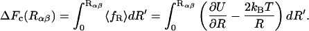
Nevertheless rare events can be studied by biasing the system and enforcing the process along a predefined reaction coordinate (RC). In the concept of constrained MD, the RC is subject to a constraint and the process is induced by controlled change of this coordinate during the simulation. With a suitably chosen geometric RC it should be possible to model a realistic pathway connected to a correspondingly low barrier in the free energy. In the case of a conformational change of a protein, the RC can be chosen as the root mean square (RMS) distance between two conformers as in the method of targeted molecular dynamics (Schlitter et al., 1993), which was applied to the conformational changes of several molecules (Jacoby et al., 1996b; Díaz et al., 1997; Ma and Karplus, 1997; Wroblowski et al., 1997). Details of pathways obtained by targeted molecular dynamics simulations were checked experimentally and proved to be predicted qualitatively correct (Kuppens et al., 1999; Diaz et al., 2000). For the present problem the distance between the centers of mass (COM) of the ligand and the protein provides a reasonable choice. Thermodynamic quantities are determined with the help of the free-energy profile that is directly computed as the integral of the mean constraint force (Mülders et al., 1996). This force can easily be calculated from a simple analytical expression that is valid for an even wider class of distance-type RCs (Schlitter et al., 2001). A new general expression is derived for the equilibrium constant of the bimolecular process under consideration that differs from the unimolecular case considered before (Schlitter et al., 2001).
Our MD simulations of the formation and dissociation of an insulin-phenol complex start from an R6 hexamer in solvent with six phenol molecules bound. The dissociation of one of the ligands is simulated with the distance of its COM from the rest of the complex as an RC. The process is modeled in two steps (Mark et al., 1994). To determine an approximate pathway for the dissociation of the complex, we performed a fast constrained MD simulation according to the slow-growth protocol. In subsequent excessively long MD simulations at fixed distances along the reaction pathway, the system is allowed to relax so that the mean force and structural data can be measured under near equilibrium conditions. The steps of the reaction mechanism are identified and, based on the evaluation of the free-energy profile, the process is characterized in terms of reaction rates and free-energy changes. The discussion is dedicated to the correlation between calculated and available experimental thermodynamic quantities that confirm the simulated mechanism.
METHODS
The decay of the protein ligand complex was modeled along the distance R of its COM. In MD simulations, the control of the RC can be achieved by application of a holonomic constraint for the distance R (Schlitter et al., 2001). In the present section, we outline the method of modeling such a reaction in constrained MD simulations and a technique to evaluate thermodynamic data of the simulated process. The first part focuses on the dynamics of the constrained system, computation of the constraint force, and realization of constrained dynamics in the MD algorithm. This is followed by a brief summary of the thermodynamic integration method to compute a free-energy profile from the mean constraint force, which is the essential tool for the thermodynamic evaluation of the reaction. The section closes with deriving expressions for the dissociation rate, the equilibrium constant of dissociation, and related thermodynamic quantities from the free-energy profile.
Constrained dynamics
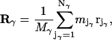
In the following, a system is regarded comprising a total number of N atoms whose positions in space are specified by a set of N Cartesian vectors (rj). This molecular system contains at least two noncovalently bound molecules, α and β. Such a molecule γ comprises Nγ atoms with a mass  located at
  Its position is characterized by the vector Rγ of its COM:
 |
(1) |
where  is the total mass of the molecule. To control the intermolecular distance
  of the molecules α and β at a given value R, a time-dependent holonomic constraint σαβ of the form
 |
(2) |
is used, which is a function of the Nαβ = Nα + Nβ coordinate vectors of the atoms of the molecules.
It is a convenient characteristic of the intermolecular constraint σαβ that it does not interfere with the usually applied intramolecular constraints  fixing covalent bond lengths between atoms i and j. Hence the constraints σαβ and
  can be treated independently of each other. The constraint σαβ is implemented into the dynamics of the system via the technique of undetermined Lagrangian multipliers (Frenkel and Smit, 1996). A term λσαβ with the time-dependent undetermined Lagrangian multiplier λ is added to the Lagrangian of the unconstrained system, which contributes a constraint force f to the equations of motion. The dynamics of the constrained system is therefore governed by the forces F due to the internal potential
  and the constraint forces
  which act on Rα and Rβ, respectively, to guarantee Eq. 2 to hold. The corresponding equations of motion for Rα,β are given by:
 |
(3) |
The numeric integration of Eq. 3 yields the time evolution of the vectors Rα and Rβ, respectively, in a constrained MD simulation. According to the leapfrog scheme chosen here, their positions at time t + Δt are:
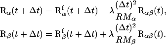 |
(4) |
In Eq. 4, a decomposition of the position vectors Rα,β(t + Δt) is carried out according to contributions  of the unconstrained free motion and a correction term
  resulting from the constraint force. The Langrangian parameter λ is calculated analytically by solving Eq. 4 for Rα,β(t + Δt). It results in a quadratic expression for λ. Of the solutions λ1 and λ2, the value with the lowest modulus is taken to generate a continuous trajectory.
The constrained variable Rαβ belongs to a class of distance-type RCs studied before (Schlitter et al., 2001), for which some important quantities can be given explicitly. The constraint results in a constant Fixman determinant,
 |
(5) |
the inverse reduced mass Mred. The constraint force fR, which is identical with the Lagrangian parameter λ, can be written as
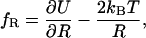 |
(6) |
which quantifies a contribution resulting from the potential U,  and a centrifugal or entropic part
  with kB Boltzmann's constant and T the absolute temperature. The free energy as a function of Rαβ takes the form
 |
(7) |
As will be shown below, the kinetic and equilibrium quantities of interest can be expressed by the differential probability P(R) to find the system at given R:
 |
(8) |
where C is a normalization factor and  For the computation of the off-rate
  we employ Eyring's transition state theory (TST) (Eyring, 1935) and for the transmission coefficient κ, Kramers' theory (Kramers, 1940).
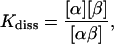
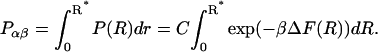
Equilibrium constant Kdiss
The equilibrium constant Kdiss of the reaction  of molecules α and β and the complex αβ, respectively, is given by
 |
(9) |
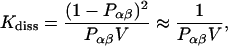
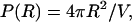
where [x] designates the respective concentrations. It suffices to consider a system consisting of one molecule α and one molecule β added to a large solvent volume V. When equilibrium is reached, the concentrations are identical with the probabilities Pα, Pβ, and Pαβ for the occurrence of molecules α, β, and the complex αβ, respectively, each divided by V. Kdiss can be expressed as
 |
(10) |
because the probability of the complex can be neglected at high dilution. When the activation barrier for dissociation is found at a distance R* between α and β, the probability for the complex is, according to Eq. 8,
 |
(11) |
The crucial normalization constant is obtained by considering the asymptotic behavior of P(R). At large distances  the interaction between the molecules α and β vanishes and the interaction with the solvent does not result in a mean force. In this regime, therefore, only the centrifugal term of Eq. 6 contributes to the mean force and the free energy profile can be written as
 |
(12) |
Therefore Eq. 8 becomes
 |
(13) |
On the other hand, we have assumed that the asymptotic probability density is 1/V, i.e.,
 |
(14) |
which by comparison yields
 |
(15) |
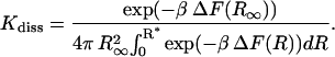
Thus the equilibrium constant takes the final form
 |
(16) |
It is easily seen that for  the expression is independent of
  as it must be.
Rate of dissociation koff
In an expression commonly used in statistical mechanics, the rate  can be written as (den Otter and Briels, 1997)
 |
(17) |
where δ(x) denotes Dirac's delta function, θ(x) the Heaviside function, and R* the position of the transition state. For the computation in a constrained MD simulation, Eq. 19 is given a slightly different shape as (den Otter and Briels, 1997):
 |
(18) |
The first factor on the right-hand side of Eq. 18 is the average positive velocity  of the RC at the transition state; the second represents the probability that the system is found in the transition state normalized by the probability that it is in the reactant space. Carrying out the integration over
  in the numerator of the first term contributes a factor
  Subsequent integration over the whole momentum space in the numerator and denominator yields (Carter et al., 1989):
 |
(19) |
The average is taken for the transition state at R*. As stated in Eq. 5, det H is, for the present case, the constant reduced mass  of the reaction partners. The second term of the RHS of Eq. 18 is computed by application of Eq. 8 so that we arrive at the final result:
 |
(20) |
To calculate the final rate  we employ Kramers' theory of the transmission coefficient κ, in which the RC undergoes a Brownian motion and shows a diffusive character. Transferring the Kramers model to the present situation, we identify the constraint force fR with the rapidly fluctuating force that causes the friction along the RC. Note that for the transition state the mean force vanishes. The constraint force satisfies to a good approximation the usual conditions of the highly fluctuating friction force of Brownian motion (Hänggi et al., 1990) at
 |
(21) |
 |
(22) |
In Eq. 22, y denotes the friction coefficient that can be directly calculated from a constrained MD simulation following the relation proposed previously (Schlitter et al., 2001):
 |
(23) |
which has to be evaluated at the top of the barrier at R*. The curvature of the free energy profile  replaces the second derivative of the potential energy U(R) in the original formulation of Kramers' theory. Corresponding to Helfand's formulation (Helfand, 1978) the transmission coefficient κ is expressed as
 |
(24) |
With the equilibrium constant and the reaction rate of dissociation at hand, we can compute the rate of association (kon) to  The free-energy changes of dissociation and association, ΔFdiss and ΔFass, and the corresponding free energies of activation,
  and
and  are determined according to the common rules of thermodynamics. In the case of dissociation they read:
 |
(25) |
 |
(26) |
where h denotes Planck's constant.
Computational details
The preparation of the system and all simulations were carried out with the GROMOS96 program package (van Gunsteren, 1996), which was augmented by algorithms to allow for the intended constrained dynamics and a temperature control using the Nosé-Hoover thermostat (Nosé, 1984).
The simulations are all based on an x-ray structure of human R6 insulin, which was kindly provided by the authors (Derewenda et al., 1989). It contains two zinc and two chloride ions, and seven phenol and 331 water molecules. Missing or incompletely resolved residues were complemented, which comprises positions B29 and B30 in all molecules as well as position B1 in molecules 3 and 6, respectively. One phenol molecule located next to one of the chloride ions and water molecules, which had a distance of more than 0.3 nm to the next protein atom or ion, was removed from the system. This molecular system was put into a periodic truncated octahedron with an edge length of 7.24 nm and filled up with water molecules of a standard configuration leaving a minimum distance of 0.8 nm between any protein atom or ion and the walls of the cube comprising the simulation box. The resulting system consists of 17,692 atoms, of which 3214 atoms account for the protein and the ions, the rest for the 4826 water molecules.
Interaction parameters for phenol were taken from the topology of tyrosine. The protonation state of the amino acid side chains was assigned according to pH 7.0–7.8, which is commonly used in experimental studies of R6 insulin.
In the simulations described below, all covalent bonds were fixed using the SHAKE procedure (Ryckaert et al., 1977), for which reason a time step Δt of 2 fs could be applied in the MD simulations. Nonbonded interactions were treated with cutoff radii of 0.8, 1.4, and 1.8 nm, respectively. Interactions were regarded only for members of the 1.4-nm pair list. The 0.8-nm pair list was generated every five steps from the 1.8-nm pair list. The two large-distance pair lists were updated automatically after longer periods according to the rules of GROMOS96 (van Gunsteren, 1996). The temperature was set to 300 K using the Nosé-Hoover thermostat with separated baths for solute, solvent, and COM of the submolecules. All single coupling strengths  were set to a common value of 0.2 ps for all baths.
To relax the solvent, the system was subjected to a steepest-descent energy minimization keeping the molecular complex of protein, phenols, and ions restrained to their original positions by application of a restrained potential with a force constant of 2.5 × 10⁴ kJ/(mol nm)2. Further relaxation was achieved in an MD simulation of 1 ps applying the same restraints to the molecular complex and using initial velocities taken from a Maxwell distribution for 300 K. This system was simulated for 1 ns during which coordinates were recorded every second picosecond and energylike quantities once per picosecond.
The coordinates of the system after 500 ps of the equilibrium run served as a starting configuration to simulate the dissociation of a single phenol molecule from the insulin hexamer. For this purpose, an arbitrarily selected phenol molecule, which is denoted as No. 6 in the crystal coordinates, was chosen. To determine an approximate pathway, the distance R between the COM of the phenol molecule and the rest of the molecular complex was increased from 1.38 to 2.23 nm in several slow-growth simulations, i.e., by applying a time-dependent constraint. R was changed by increments of 0.1 nm in simulations over 50 ps, each slow-growth simulation being followed by a relaxation run of another 50 ps at fixed RC before the next slow-growth simulation was started. Likewise, a new starting position was determined by decreasing R to 1.28 nm. From the slow-growth trajectories, 20 configurations at equidistant values Ri (1.28 nm ≤ Ri ≤ 1.38 nm) were extracted representing a first approximation to the reaction pathway. For each of these 20 fixed Ri, the further evolution of the system was observed in subsequent simulations covering at least 1 ns. The exact simulation time varied according to the appearance of relaxation processes. In these MD simulations, coordinates were written to tape every second picosecond, energylike quantities every half picosecond, and the constraint force was noted in each step.
RESULTS
The presentation of the results is split in two parts: the characterization of the structural events accompanying the association/dissociation of the insulin-phenol complex and the thermodynamic analysis of the process. The latter confirms the existence of a stable state at R ≈ 1.38 nm in agreement with the x-ray data, and positions the transition state at a value of the reaction coordinate R ≈ 1.87 nm, which is important information for interpreting the geometrical findings.
Structural description
The snapshots shown in Fig. 4 give a visual impression of the sequence of events and the dynamics of the process. The pictures are ordered according to increasing distance R of the ligand to the protein's COM, which is the reaction coordinate. For optimal presentation of the occurring motions, only the phenol is rendered as space filling whereas the protein is represented by its backbone. The view is slightly more from below and from the right-hand side than in Fig. 3 so that the binding pocket opens to the left. The bound state (R ≈ 1.38 nm) is characterized by H-bonds between phenol and the backbone of the neighboring cysteines (yellow/red) and by nearly free rotations of the carbon ring about its “long axis” (see Fig. 8). At the beginning of the dissociation reaction, the H-bonds are opened sequentially (R ≤ 1.68 nm). At the same time, the residues Ser 6A9 and Ile 6A10 (green/cyan) undergo larger position displacements. Next, up to R = 1.88 nm, the carbon ring of the ligand performs considerable reorientations that enable the ligand to enter the exit channel made up of His 4B5 and Cys 6A11(orange/yellow) and pass through it. At this stage the hydroxyl group of the ligand already enters the solvent environment and RMS displacements of Ser 6A9, Ile 6A10, and Cys 6A11 (green/cyan/yellow) reach their maximum. According to the maximum of the free-energy profile, this very configuration (R = 1.87 nm) is identified as the transition state. At larger values of R, the complex dissociates, residues relax toward their initial positions, and the ligand is located on the surface of the protein. At distances R ≥ 2.03 nm, the insulin and the phenol molecules are completely separated. The analysis of the reaction essentially shows that only the five amino acids mentioned are involved in the formation and decay of the complex. This result confirms the assumption that the process is based on local interactions and is not cooperative. Because it is restricted to the named residues, the according volume change can be neglected, i.e., ΔV ≈ 0. Hence the free energy ΔF, which is considered below, and the free enthalpy ΔG are approximately equal, ΔG ≈ ΔF.
FIGURE 4.

Snapshots of the escape of phenol from the binding pocket as obtained from equilibrations at indicated intermediate values of the reaction coordinate. The perspective is different from that of the previous figures (see text). Backbone sections of relevant residues are colored for Leu B11 (dark green), His B5 (orange), Ser A9 (green), Ile A10 with side chain (cyan), Cys A11 (yellow), and Cys A6 (red). The nomenclature was simplified by omitting the number of the subunit.
FIGURE 8.

Eulerian angles (φθψ) describing the orientation of phenol relative to insulin. The z axis is the symmetry axis of the hexamer; z′ denotes the “long” axis of phenol.
The following, more detailed analysis of the reaction deals with the structural changes in insulin, the dynamics of the ligand, and lastly the role of the solvent environment. Because of the obviously local character of the process, the structural analysis is restricted to residues of the binding site, i.e., in the direct neighborhood of the phenol molecule. Neighbor residues were defined as having an average distance to the phenol molecule of not more than 0.5 nm in a simulation with fixed value of the reaction coordinate. Besides the residues usually assigned to the binding site (His 4B5, Cys 6A6, Cys 6A11, and Leu 6B11), positions between the disulfide-bonded Cys 6A6 and Cys 6A11 (Cys 6A7, Thr 6A8, Ser 6A9, and Ile 6A10), Leu 3B17, Val 4B2, and His 6B10 were identified as neighbors along the reaction pathway. To extract residues involved in the binding process, we monitored the RMS displacement from the crystal structure for all residues lining the reaction pathway.
Cys 6A6 and 6A11 essentially stabilize phenol binding by providing the acceptor (carbonyl group of A6) and donor (amide group of A11) for hydrogen bonds to the phenol hydroxyl group. Little flexibility is expected from these disulfide-bonded cystein residues and so the observed positional shifts are very limited. For Cys 6A11, the average over all atoms shows a long-lived displacement of up to 0.1 nm at the transition state compared to the initial state. These restricted positional changes are, however, indicative of the local structural tension near Cys 6A11 because they are correlated with the fluctuation and relaxation of the constraint force as can be seen in Fig. 5.
FIGURE 5.

Displacement of Cys A11 (RMS averaged over all atoms) and cumulative mean of the constraint force fR at R = 1.68 nm. The displacement is indicative of (and probably partially responsible for) the force opposing the dissociation at this stage, which is already close to the activation barrier. The apparent relaxation of the force is accompanied with the residue's return to its x-ray position.
From the residues located between the positions A6 and A11, Cys 6A7 and Thr 6A8 neither show noticeable shifts nor can a perceptible function for the process be assigned to them. The situation looks different for Ser 6A9 and Ile 6A10, as shown in Figs. 6 and 7, respectively.
FIGURE 6.

RMS displacement of Ser A9 against the reaction coordinate. The gray section represents the displacement of the Cα atom, the whole bar the average over all atoms. The residue transiently moves away from its x-ray position, the maximum displacement occurring at the transition state (R = 1.87 nm).
FIGURE 7.

RMS displacement of Ile A10 against the reaction coordinate analogous to Fig. 6. It transiently moves away from its x-ray position with a maximum displacement at the transition state (R = 1.87 nm). This movement is exceptionally pronounced and clearly correlated with the opening phase of the binding pocket. The black line is the profile of free energy discussed in the thermodynamics section.
These residues are both subject to increasing displacements during the course of the reaction culminating at the transition state. Ile 6A10 undergoes the largest movement of all residues with 0.54 nm for all of its atoms and 0.38 nm for the Cα atom. At larger values of the RC, relaxation toward the initial state is observed, although in the case of Ile 6A10, RMS deviations from the crystal structure are significantly larger in the state without phenol than in the initial state with the binding site occupied. The positional shifts occur in a concerted movement of side chain and backbone atoms as can be taken from the corresponding RMS deviations that are running almost parallel for both residues, suggesting that the structure of the binding site changes moderately with the binding/dissociation process. All other neighboring residues show less significant RMS deviations and could not be assigned a defined role.
It is a reasonable suggestion that the positional shifts are connected with torsions of the dihedral angles (ϕ, ψ) between Cys 6A6 and Cys 6A11. An analysis of the corresponding set of (ϕ, ψ) angles reveals a closer view of the underlying phenomenon. Although dihedral angles seem to be distributed and change more or less irregularly along the backbone, their fluctuations steadily increase from the initial to the transition state. These changes can amount to up to 100% as in the case of the angle ϕ between Thr 6A8 and Ser 6A9 whose RMS-fluctuations increase from ∼11° to ∼23°.
So the large positional deviations of Ser 6A9 and particularly Ile 6A10 can be partly attributed to a torsion of the corresponding dihedrals between Cys 6A6 and Cys 6A11. The generated stress is distributed over almost all pairs of (ϕ, ψ) of this area and is reflected more by increased fluctuations than by a clear tendency of the averages. This phenomenon is a known characteristic of the dynamics of proteins that react to local displacements as an elastic continuum (McCammon and Harvey, 1987).
Next we address the dynamics of phenol in the course of the decay related to the structural changes of insulin considered above. Whereas interactions of the hydroxyl group with the environment are dominated by hydrogen bonding and electrostatic forces, the aromatic ring mainly interacts via van der Waals forces and acts as a rigid body.
From the initial to the transition state, neighbors of the hydroxyl group are essentially the polar backbone atoms of Cys 6A6 and Cys 6A11 and, to a smaller extent, the carbonyl oxygen of Ser 6A9 and Ile 6A10. In the initial state, the position of the ligand in the binding site is stabilized by H-bonds of the hydroxyl group to the amide proton of Cys 6A11 and the carbonyl oxygen atom of Cys 6A6. The H-bond between the amide proton of Cys 6A11 and hydroxyl oxygen of phenol is the most stable one and is resolved only at an RC of 1.83 nm. The contacts of the hydrogen atom of the hydroxyl group are more flexible due to free rotations around the carbonyl oxygen axis. Its H-bond to the carbonyl oxygen atom of Cys 6A6 is repeatedly broken and reestablished before it completely disappears for distances larger than R > 1.68 nm. Although more loosely, the amide hydrogen is also repeatedly in contact with the carbonyl oxygen atom of Ser 6A9 with large fluctuations of the interatomic distance and disappears for R > 1.68 nm. Ile 6A10 is not a direct neighbor of the hydroxyl group. Its carbonyl and amide group are turned away from the hydroxyl group and there are no polar atoms for interaction. The situation changes with further increase of R. Up to the transition state, the hydroxyl group and the unpolar Cγ atoms of the Ile 6A10 side chain approach each other to within ∼0.4 nm; the hydroxyl group has no more neighbors in the protein within the considered sphere of radius 0.5 nm except for His 4B5 and Cys 6A11. In the course of this process, the hydroxyl group directs itself more and more toward the solvent. At R = 1.73 nm, the distance between the hydrogen atom of the hydroxyl group and the next water atom is only to 0.33 ± 0.12 nm and it further decreases with increasing R.
The dynamics of the aromatic ring of phenol is of utmost interest from the thermodynamical point of view. It will be characterized in the following by its orientation (Eulerian angles shown in Fig. 8) and neighbor contacts throughout the process.
In the initial state (R = 1.38 nm), the top of the ring in Fig. 8, the carbon C4 can either be in close proximity to the main chain atoms of His 6B10 and Leu 6B11, or alternatively to a lesser extent also to the imidazol ring of His 4B5. Here the interatomic distances amount to 0.35 nm in the first case, whereas in the second a distance of ∼0.4 nm is observed. RMS-fluctuations of the Eulerian angles φ and θ in this state are quite restricted and these angles are well defined, whereas the ring can move relatively freely around the z′ axis (angle ψ) . In the course of the dissociation, the orientation angles (φθ) and their RMS fluctuations continuously change. At R = 1.63 and 1.68 nm, the orientation between the z′ axis of the aromatic ring and the insulin z axis has shifted from 140.3° in the initial state to an almost perpendicular inclination. At this stage, which is characterized by the final disruption of H-bonds of the hydroxyl group, the corresponding θ angles are 97.5° (R = 1.63 nm) and 101.1° (R = 1.68 nm). Phenol is located between Cys 6A11, whose carbonyl oxygen atom is still in contact with the hydroxyl group (H-bond), and His 4B5, which is in close proximity to the top of the aromatic ring, the atoms C4 and H4 (distances 0.4 nm).
For larger values of R (1.73, 1.78, and 1.83 nm) up to the transition state, the carbon ring has to enter the path constituted by His 4B5 on the one side of the ring plane and Cys 6A11 and Ile 6A10 on the other to open this channel that still is partially closed and pass through it. Entrance into the channel is achieved by reorientations of the angles θ and particularly φ, which was below 60° and now rises at small RMS fluctuations to values of 134° up to 185° inside the channel (1.73 nm ≤ R ≤ 1.83 nm). In this phase of the reaction, rotations of the carbon ring around the z axis are strongly suppressed, the ring approaches the main chain atoms of Cys 6A11 to up to 0.3 nm, and the ligand molecule enters the solvent environment with the hydroxyl group first. At a distance of 1.88 nm, displacements of the involved residues reduce and orientation of the carbon ring becomes a bit more flexible. With a further increase of R, the phenol molecule is at first fixed on the surface of the protein and retains contact to atoms of insulin at R = 1.98 nm. For R ≥ 2.03 nm, the system is completely dissociated. This last phase of dissociation is characterized by its angles’ fluctuations (see Fig. 9). Although the angles show small fluctuations about one or more possible orientations as long as phenol is in the pocket or on the surface, they take a random distribution after complete dissociation. A quantitative analysis will be presented below.
FIGURE 9.

Time behavior of the Eulerian angles (φθψ) at different stages of the process. Over most of the pathway, restricted fluctuations about one or two well-defined orientations are observed. Note that this particular pattern does not change at the passage over the activation barrier (close to R = 1.88 nm, top right), but only later after the dissociation of the ligand from the protein surface (R ≥ 2.03 nm).
One aspect of the dissociation is the induced flow of water into the binding site substituting for the ligand. To calculate the number of water molecules inside the binding site, the pocket was mapped to a cylinder of radius 0.4 nm whose axis is given by connecting the Cγ atom of His 4B5 and the amide nitrogen atom of Leu 6B11; the number of water molecules inside the cylinder was monitored for all equilibrium simulations (1.28 nm ≤ R ≤ 2.23 nm). Because the choice of this cylinder does not reflect the specific geometric proportions of the binding site, additionally neighbor lists and visual analysis were used for the evaluation. In the initial state (R ≤ 1.38 nm), there are ∼2–3 water molecules in the binding pocket. With growing R, accompanied by a deformation of the binding site, the number of solvent molecules increases to six and then to seven close to the transition state. For yet larger values of R (R ≤ 1.98), the number of solvent molecules inside the binding site amounts to ∼8. These additional molecules occupy the end of the channel between His 4B5 and Cys 6A11. In the further course of the process, the site again adopts a more compact shape with space to host ∼4–5 water molecules. But packing remains a bit looser in the dissociated than in the initial state.
Thermodynamics
As pointed out in the computation section, forces were sampled over at least 1 ns at each distance, which was regarded as a reasonable period. Examples of the time course of the constraint force and accumulated averages for several distances are shown in Figs. 10 and 11, respectively.
FIGURE 10.

The constraint force fR at R = 1.63 nm (black). The white curve is a 4-ps average.
FIGURE 11.

Accumulated mean of the constraint force for different values of the reaction coordinate R.
The force exhibits considerable noise with correlation times τf, which usually are below 1 ps and never longer than 1.5 ps. Accordingly, the statistical error varies from 4 to 15 kJ/(mol nm) if equilibrium is assumed. The accumulated averages indicate a nonuniform relaxation behavior tending to values that seem to be approximate equilibrium values. Nevertheless, the restricted time period, like any other, does not guarantee full convergence as longtime relaxation effects and the occurrence of slower system modes cannot be excluded.
The profile of the mean constraint force plotted against the RC in Fig. 12 reflects the course of the reaction. At distances R smaller than 1.88 nm, the constraint force (which acts against the locally felt mean force) prevents the system from reinstalling the initial state around 1.35 nm. For larger values of R, the constraint force decreases, changes sign, becomes significantly smaller, and finally vanishes (within the limits of errors), i.e., we observe that after dissociation from the protein, the phenol molecule becomes practically free from any directed interaction. In this regime the constraint force is governed by its entropic part only as shown in the methods section.
FIGURE 12.

Profile of the mean constraint force, the bars marking the statistical errors. The flat thin line is the expected entropic force that remains when the interaction between phenol and insulin disappears.
Numerical integration of the forces shown in Fig. 12 results in the free-energy profile of Fig. 13. It shows the expected shape with two valleys separated by a maximum. The bound state is represented by a pronounced valley within distances up to 1.87 nm where the maximum marks the transition state, and the valley of the dissociated state is indicated by the decrease for larger distances. The exact position of the maximum was determined by quadratic interpolation, which simply is linear interpolation of the forces.
FIGURE 13.

The profile of the free energy, ΔF, computed as the integral over the mean constraint force. The transition state at R = 1.87 nm (maximum) separates the bound state of the insulin-phenol complex (deep left minimum) from the dissociated state (beginning decline for large R).
In the first phase up to a distance of 1.83 nm, the ligand finds its way through the binding pocket to the surface of the protein. Although the position of the transition state is clearly defined by its thermodynamic characteristics, its structural properties are more difficult to define. According to Fig. 7, the activated state is connected with a maximum displacement of Ile A10, which apparently blocks the exit of the binding pocket. But we also observe transient dissociation of the system already at fixed distances of 1.83 and 1.88 nm. On the other hand, transient contacts between surface residues and the phenol still occur at distances from 1.88 to 1.98 nm. Further increase of the reaction coordinate completes the decay of the complex by complete transfer of the ligand to the solvent.
The difference in the free energy between the clear minimum of the bound state and the barrier amounts to ∼35 kJ/mol. The emerging dissociated state is only suggested by a small decrease of free energy, which certainly does not reflect the observed gain of rotational freedom between R = 1.98 and 2.03 nm (Fig. 9) of the phenol molecule when entering the solvent environment. Apparently the constraint force against the selected reaction coordinate cannot represent the abrupt onset of almost free rotation. This point, however, affects neither the position of the activation barrier (R = 1.87 nm) nor its height relative to the bound state.
We therefore calculate separately the change in free energy of rotation from the angle fluctuations near the transition state (R = 1.83 nm ) and after dissociation as
 |
(27) |
where  and
and  denote the mean and the RMS fluctuation of the Eulerian angle
  respectively. The assumption underlying Eq. 27 is an equidistribution after dissociation and an essentially entropic effect of the angular restrictions observed before. The resulting
  is an important contribution to the free-energy difference of dissociation
  .
.  is computed from the free-energy profile using Eq. 16. For this purpose, the required distance
  (where the molecules can be considered free) was set to 2.21 nm in accordance with the discussion above and the data shown in Fig. 12. For the total free-energy difference of dissociation, we obtain
  or, equivalently, an equilibrium constant of dissociation of
  i.e., in equilibrium the system clearly favors the bound state. The dissociated state, on the other hand, appears to be stabilized largely by its rotational entropy, which results in a free-energy of rotation of −14.3 kJ/mol. It is noted that an analysis of the energy itself was not performed with respect to the high fluctuations this quantity and its components are subject to.
Kinetics
For the computation of kinetic quantities, it is important that the regime from the bound to the activated state is not affected by the sudden rotations. The TST rate constant  calculated from Eq. 22 is (726 ± 361) ms−1, and the corresponding
  is (4.90 ± 2.50) (ns mol/l)−1. An overview of equilibrium and activation quantities is given in Table 1.
TABLE 1.
Equilibrium and kinetic quantities obtained by the simulation of the formation and decay of the insulin-phenol complex
| Equilibrium | TST kinetics | Corrected kinetics | ||
|---|---|---|---|---|
 |
mol/l | (1.48 ± 1.02)×10−4 | ||
 |
kJ/mol | 21.79 ± 2.82 | ||
 |
kJ/mol | −14.32 ± 2.25 | ||
 |
kJ/mol | 39.43 ± 1.23 | 48.85 ± 1.76 | |
 |
kJ/mol | 17.65 ± 1.24 | 27.07 ± 1.77 | |
 |
ms−1 | 726 ± 361 | 16.04 ± 11.45 | |
 |
(ns mol/l)−1 | 4.90 ± 2.50 | 108.25 ± 77.42 | |
| κ | – | 0.022 ± 0.011 |
The calculated TST rates suggest that the process is extremely fast, but experimental kinetic measurements of similar systems, T3R3 insulin with 2,6- and 2,7-dihydroxynapthalene (DHN) as a ligand, show the dissociation to take place on the millisecond timescale (Bloom et al., 1997). These findings are indicators of a correspondingly small transmission coefficient, κ, which has already been observed for other processes in a protein environment (Schlitter et al., 2001). As outlined in the method section, we compute κ implicitly using Kramers' theory. An alternative technique would be the reactive flux method (Chandler, 1978; Ruiz-Montero et al., 1997), in which κ is determined by additional time-consuming computer experiments.
According to Eqs. 23 and 24, κ is determined by the curvature of the free-energy profile at the top of the barrier and the integral of the autocorrelation function of the constraint force, in the transition state. As before the position of the transition state, now also the curvature  is computed by parabolic interpolation, which reduces to linear interpolation of the mean force. The profile evaluated at distances R of 1.83, 1.88, and 1.93 nm yielded c = −506.9 kJ/(mol nm2). The integral Eq. 23 calculated from the trajectory of fR at a distance of 1.83 nm results in a value of 24,400 (kJ/(mol nm))2 ps. This eventually yields a transmission coefficient κ of 0.022 ± 0.011, which reduces the rates to only 2 percent and emphasizes the importance of friction on the kinetics of the process. The rate constants corrected by κ are now ∼50 times smaller,
  and
and  Table 1 gives an overview of rates and free energies of activation including κ.
The thermodynamic and kinetic results can be compared to data of experiments made on insulin-phenol complexes and similar systems. The dissociation constant  for phenol binding in zinc insulin was determined to (3.6 ± 0.8) × 10−4 mol/l by Jacoby et al. (1993) and to (2.0 ± 1.0) × 10−4 mol/l by Bloom et al. (1998). The corresponding free enthalpies
  are 19.8 ± 0.3 kJ/mol and 21.2 ± 1.0 kJ/mol, respectively. The free energy of dissociation computed from our simulations, ΔFdiss = 21.79 ± 2.82 kJ/mol, is in good accordance with the experimental values within error boundaries. The kinetics of phenol binding is not accessible. In their NMR studies, Jacoby et al. (1996a) only showed that the off-rate must be larger than 0.1/ms. Bloom et al. (1997) were able to measure the dissociation rates
  of the ligands 2,6- and 2,7-DHN from cobalt-substituted T3R3-Co-insulin. With 0.22/ms for 2,6-DHN and 0.46/ms for 2,7-DHN, these ligands show a slower dissociation than expected for the smaller phenol. Our simulations indeed yield a value
  that is larger but of similar magnitude. Hence the computed rates are fully consistent with the experimental findings.
SUMMARY AND CONCLUSION
As an example of problems that can be treated using the recently developed computation of free-energy profiles along a reaction coordinate, we have considered the interaction between insulin and one of its phenol ligands which can noncovalently bind inside the protein. Starting from an x-ray structure of R6 insulin hexamer with six phenols bound, we first applied constrained MD simulation to determine a preliminary pathway for the ligand by slowly moving it away from its binding site. The technique was also used to equilibrate the system over long times at fixed intermediate values of the reaction coordinate to improve the pathway and to monitor the mean force. We thus were able to calculate the equilibrium constant and rates that turned out to agree well with experiments. Apart from the theoretical and numerical feasibility, our interest was in a detailed mechanism of the dissociation of the insulin-phenol complex, which possibly is of interest for engineering insulin. To our knowledge, this is the first application of the new methodology to theoretically study a slow protein-ligand interaction in atomic detail. Therefore we will summarize not only the results, but also the important methodological basis.
Mechanism of the reaction
The understanding of the mechanism in terms of structural events is facilitated by the knowledge of the free-energy profile. Phenol is bound and partially buried in a rather hydrophobic pocket (Figs. 2 and 3). The bound state of phenol is characterized by H-bonds between the phenol hydroxyl group and the backbone of Cys 6A6 and 6A11, and an otherwise freely rotating carbon ring. Rupture of the H-bonds as a first step requires the residues Ser 6A9 and Ile 6A10 to give way. In the following steps the carbon ring of the ligand undergoes considerable reorientations, which allow it to enter the exit channel between His 4B5 and Cys 6A11 and pass through it with the hydroxyl group of the ligand in front (Fig. 4). This is the state of maximum free energy, the transition state, where the displacement of Ser 6A9, Ile 6A10, and Cys 6A11 also reach their maximum. Structurally the side chain of Ile 6A10 is the real obstacle for the escaping ligand. Its displacement is most closely correlated with the increase in free energy (Fig. 7). It comprises both bending of the short side chain and the backbone, and results in a shift of the neighboring residues whose side chains point away from the phenol (Fig. 3). The analysis of the reaction shows that essentially not more than five amino acids of insulin are involved in the process, which appears to be local and not cooperative. This together with the observation that the escaping phenol is readily replaced by water justifies the assumption of a negligible volume change, ΔV ≈ 0 and the approximate replacement of the free enthalpy by the free-energy change, ΔG ≈ ΔF.
Thermodynamics
The calculated profile of the free energy represents the bound state of the complex as a deep minimum, a transition state that belongs to the passage described above, and a slow asymptotic decrease in accordance with theory (Fig. 13). The sudden onset of free rotation beyond the activation barrier results in a further entropic contribution of −14.3 ± 2.3 kJ/mol to the free energy of dissociation ΔFdiss of 21.8 ± 2.8 kJ/mol. The equilibrium constant Kdiss = (1.5 ± 1.0) 10−4 mol/l shows that the bound state clearly dominates the distribution of species although the dissociated state is favored by the rotational entropy of the ligand.
The rate of dissociation was calculated to (16.0 ± 11.5)/ms, which corresponds to a free energy of activation,  of 48.9 ± 1.8 kJ/mol. The corresponding values for
  and
and  amount to 108.3 ± 77.4 (μs mol/l)−1 and 27.1 ± 1.8 kJ/mol, respectively. The activation quantities calculated according to the Eyring theory experience a dramatic correction by the extremely small transmission coefficient κ of 0.022 ± 0.011 computed according to the Kramers theory.
Methodology
The distance R between the COM of the selected phenol molecule and the rest of the complex was chosen as a reaction coordinate. Two types of constrained MD simulations were performed. The first one comprises a “fast” enforcement of the reaction, i.e., starting from the bound state, the selected ligand molecule is pushed out of the binding pocket (1.28 nm ≤ R ≤ 2.23 nm) using a time-dependent constraint similar to the parameter in the slow-growth method. The second one consists of sequential long MD simulations (≥1 ns) at 21 equidistant fixed values of the RC to obtain relaxation and sufficient statistics (Mark et al., 1994) for the quantities of interest, in particular the mean constraint force. Computation of thermodynamic quantities is based on the evaluation of the free-energy profile calculated as the integral of mean constraint force (Mülders et al., 1996). An expression for the dissociation constant of the chosen reaction coordinate has been derived here. The dissociation rate was computed according to the TST theory and with a transmission coefficient using the Kramers theory analogous to the example given previously (Schlitter et al., 2001).
Reaction coordinate and pathway
The distance R between the COM of the two molecules is a reasonable choice when considering the geometrical facts (Figs. 1–3). Application of a constraint for R, i.e., fixing only one degree of freedom, leaves the system with a maximum of flexibility to find a pathway with low barriers in free energy. Although the preliminary pathway was determined by enforced dissociation, the later equilibrated 21 reference-structure pathway is likely to be valid for both dissociation and association. However, the use of a global reaction coordinate, i.e., the same for all phases of a reaction, is always questionable. Discontinuities of any kind can indicate transitions that are not seen along the chosen RC, but are possibly resolved when using a different, locally appropriate RC (Neria et al., 1996). In the present example, the sudden gain of rotational freedom of the ligand is a transition of that type. We did not try to find a suitable coordinate for the problematic interval, but confined ourselves to computing the corresponding free-energy contribution from the angle distributions.
Constraint force and free energy
The duration of the single-constraint MD simulations to record statistics of thermodynamic and structural data is subject to two criteria. It must be sufficiently long that the system can relax from initially nonequilibrium states, and slow-system modes must be statistically well represented (Mark et al., 1994). As an indicator of convergence, the accumulative mean of the constraint force can be used. Unfortunately, this is no guarantee that the system is sufficiently sampled. As a practical solution to this problem, we decided to regard the mean as converged if its tendency at the end of the simulation is within the boundaries of the statistical error. In most cases, the single mean force bears a considerable, probably bigger than statistical error that was taken into account (see Figs. 10 and 11) and the related discussion. Being aware of this problem, it is obvious how important additional experimental information is to validate results obtained from MD simulations.
Simulation and experiment
For phenol as a ligand, only the change in free enthalpy, ΔGdiss, could be measured so far with good accuracy. The values of 19.8 ± 0.3 kJ/mol and 21.1 ± 1.7 kJ/mol (Jacoby et al. 1993; Bloom et al., 1998) are within the error boundaries in acceptable agreement with the ΔFdiss of 21.8 ± 2.8 kJ/mol obtained from our MD simulations.
Experimentally the rate of dissociation was only determined to be larger than ∼0.1 ms−1 (Roy et al., 1989), but the corresponding rates for two larger ligands, 2,6- and 2,7-DHN, are known to be 0.22 ms−1 and 0.44 ms−1, respectively (Bloom et al., 1997). Apparently the calculated dissociation rate kdis of 16 ms−1 for phenol is consistent with these data because the escape of the much larger DHNs from the binding niche is indeed expected to be slower.
Interestingly the simulations also confirm the mechanistic picture that was derived from proton-NMR experiments on the R6 human insulin hexamer (Jacoby et al., 1996a,b). The existence of a flexible portal for phenol with functional fluctuations of only a restricted neighborhood in the otherwise stable hexameric complex was observed here, too. In particular, Ile A10 proves to be the “gatekeeper” residue, the existence of which was already inferred from the experiments (Jacoby et al., 1996a,b). Moreover the simulations provide information about side chain and/or backbone deformations at each residue and their correlation with ligand movements, which can be important for engineering purposes.
Summarizing the results, the simulation of the formation and decay of the insulin-phenol complex yields a detailed picture of the underlying mechanism of the process. The proposal for the mechanism of the reaction derived from the simulations is essentially supported by the agreement and consistency of the computed structural and thermodynamic data with their experimental counterparts. The computed (and experimental) duration of this dissociation reaction amounts to ∼0.1 ms and thus is ∼3 orders of magnitudes larger than the overall simulation period. With the applied technique of constrained MD simulations and corresponding evaluation methods, we are able to study a process of such complexity in a feasible amount of computer time.
It may be possible to apply the method presented here to the simulation of other protein-ligand interactions, which is a challenging field for theoretical and practical reasons. The present scheme to model the process by using one global reaction coordinate and correcting only the free energy of dissociation can be applied in similar cases where rotational freedom is achieved far from the transition state. For more complicated cases (Neria et al., 1996), the improvement of the tentative pathway by introducing piecewise valid local reaction coordinates is a more general promising approach.
Acknowledgments
A.W. thanks Sir Tom Blundell, Dietrich Brandenburg, Pierre De Meyts, Guy Dodson, Jörg Fleischhauer, Dan Mercola, and Robert Woody for 30 years of friendly collaboration.
This work was supported in parts by grants from the Deutsche Forschungsgemeinschaft and the VolkswagenStiftung.
References
- Altobelli, G., and S. Subramaniam. 2000. Kinetics of association of anti-lysozyme monoclonal antibody D44.1 and hen-egg lysozyme. Biophys. J. 79:2954–2965. [DOI] [PMC free article] [PubMed] [Google Scholar]
- Baker, E. N., T. L. Blundell, J. F. Cutfield, S. M. Cutfield, E. J. Dodson, G. G. Dodson, D. M. Crowfoot Hodgkin, R. E. Hubbard, N. W. Isaacs, C. D. Reynolds, K. Sakabe, N. Sakabe, and N. M. Vijayan. 1988. The structure of 2Zn pig insulin crystals at 1.5 Å resolution. Philos. Trans. R. Soc. Lond. B. 319:369–456. [DOI] [PubMed] [Google Scholar]
- Bentley, G., E. Dodson, G. Dodson, D. Hodgkin, and D. Mercola. 1976. Structure of insulin in 4-zinc insulin. Nature. 261:166–168. [DOI] [PubMed] [Google Scholar]
- Berchtold, H., and R. Hilgenfeld. 1999. Binding of phenol to R6 insulin hexamers. Biopolymers. 51:165–172. [DOI] [PubMed] [Google Scholar]
- Birnbaum, D. T., M. A. Kilcomons, M. R. DeFelippis, and J. M. Beals. 1997. Assembly and dissociation of human insulin and LysB28ProB29-insulin hexamers: a comparison study. Pharm. Res. 14:25–36. [DOI] [PubMed] [Google Scholar]
- Bloom, C. R., R. Heymann, N. C. Kaarsholm, and M. F. Dunn. 1997. Binding of 2,6- and 2,7- dihydroxynaphthalene to wild-type and E-B13Q insulins: dynamic, equilibrium, and molecular modeling investigations. Biochemistry. 36:12746–12758. [DOI] [PubMed] [Google Scholar]
- Bloom, C. R., N. Wu, A. Dunn, N. C. Kaarsholm, and M. F. Dunn. 1998. Comparison of the allosteric properties of the Co(II)- and Zn(II)-substituted insulin hexamers. Biochemistry. 37:10937–10944. [DOI] [PubMed] [Google Scholar]
- Brange, J., and L. Langkjaer. 1992. Chemical stability of insulin. 3. Influence of excipients, formulation, and pH. Acta Pharm. Nord. 4:149–158. [PubMed] [Google Scholar]
- Carter, E. A., G. Ciccotti, J. T. Hynes, and R. Kapral. 1989. Constrained reaction coordinate dynamics for the simulation of rare events. Chem. Phys. Lett. 156:472–477. [Google Scholar]
- Chandler, D. 1978. Statistical mechanics of isomerization dynamics in liquids and the transition state approximation. J. Chem. Phys. 68:2959–2970. [Google Scholar]
- Daura, X., B. Jaun, D. Seebach, W. F. van Gunsteren, and A. E. Mark. 1998. Reversible peptide folding in solution by molecular dynamics simulation. J. Mol. Biol. 280:925–932. [DOI] [PubMed] [Google Scholar]
- den Otter, W. K., and W. J. Briels. 1997. Molecular dynamics simulations of free energy and conformational transition rates of calix[4]arene in chloroform. J. Chem. Phys. 107:4968–4978. [Google Scholar]
- Derewenda, U., Z. Derewenda, E. J. Dodson, G. G. Dodson, C. D. Reynolds, G. D. Smith, C. Sparks, and D. Swenson. 1989. Phenol stabilizes more helix in a new symmetrical zinc insulin hexamer. Nature. 338:594–596. [DOI] [PubMed] [Google Scholar]
- Diaz, J. F., M. M. Escalona, S. Kuppens, and Y. Engelborghs. 2000. Role of the switch II region in the conformational transition of activation of Ha-ras-p21. Protein Sci. 9:361–368. [DOI] [PMC free article] [PubMed] [Google Scholar]
- Díaz, J. F., B. Wroblowski, J. Schlitter, and Y. Engelborghs. 1997. Calculation of pathways for the conformational transition between the GTP- and GDP-bound states of the Ha-ras-p21 protein: calculations with explicit solvent simulations and comparison with calculations in vacuum. Proteins: Struct. Funct. Genet. 28:434–451. [PubMed] [Google Scholar]
- Duan, Y., and P. A. Kollman. 1998. Pathways to a protein folding intermediate observed in a 1-microsecond simulation in aqueous solution. Science. 282:740–744. [DOI] [PubMed] [Google Scholar]
- Eyring, H. 1935. The activated complex in chemical reactions. J. Chem. Phys. 3:107–115. [Google Scholar]
- Frenkel, D., and B. Smit. 1996. Understanding Molecular Simulation. Academic Press, San Diego.
- Hänggi, P., P. Talkner, and M. Borkovec. 1990. Reaction-rate theory: fifty years after Kramers. Rev. Mod. Phys. 62:251–341. [Google Scholar]
- Hassiepen, U., M. Federwisch, T. Mülders, and A. Wollmer. 1999. The lifetime of insulin hexamers. Biophys. J. 77:1638–1654. [DOI] [PMC free article] [PubMed] [Google Scholar]
- Helfand, E. 1978. Brownian dynamics study of transitions in a polymer chain of bistable oscillators. J. Chem. Phys. 69:1010–1018. [Google Scholar]
- Jacoby, E., P. Krüger, Y. Karatas, and A. Wollmer. 1993. Distinction of structural reorganisation and ligand binding in the T↔R transition of insulin on the basis of allosteric models. Biol. Chem. Hoppe-Seyler. 374:877–885. [DOI] [PubMed] [Google Scholar]
- Jacoby, E., Q. X. Hua, A. S. Stern, B. H. Frank, and M. A. Weiss. 1996a. Structure and dynamics of a protein assembly. 1H-NMR studies of the 36 kDa R6 insulin hexamer. J. Mol. Biol. 258:136–157. [DOI] [PubMed] [Google Scholar]
- Jacoby, E., P. Krüger, J. Schlitter, D. Röper, and A. Wollmer. 1996b. Simulation of a complex protein structural change: the T↔R transition in the insulin hexamer. Protein Eng. 9:113–125. [DOI] [PubMed] [Google Scholar]
- Karatas, Y., P. Krüger, and A. Wollmer. 1991. Kinetic measurements of T→R structural transitions in insulin. Biol. Chem. Hoppe-Seyler. 372:1035–1038. [DOI] [PubMed] [Google Scholar]
- Kramers, H. A. 1940. Brownian motion in a field of force and the diffusion model for chemical reactions. Physica. 7:284–304. [Google Scholar]
- Kuppens, J., F. Diaz, and Y. Engelborghs. 1999. Characterization of the hinges of the effector loop in the reaction pathway of the activation of ras-proteins. Kinetics of bonding of beryllium trifluoride to V29G and I36G mutants of Ha-ras-p21. Protein Sci. 8:1860–1866. [DOI] [PMC free article] [PubMed] [Google Scholar]
- Ma, J., and M. Karplus. 1997. Molecular switch in signal transduction: reaction paths of the conformational changes in ras p21. Proc. Natl. Acad. Sci. USA. 94:11905–11910. [DOI] [PMC free article] [PubMed] [Google Scholar]
- Mark, A. E., S. P. van Helden, P. E. Smith, L. H. M. Janssen, and W. F. van Gunsteren. 1994. Convergence properties of free energy calculations: α-cyclodextrin complexes as a case study. J. Am. Chem. Soc. 116:6293–6302. [Google Scholar]
- McCammon, J. A., and S. C. Harvey. 1987. Dynamics of Proteins and Nucleic Acids. Cambridge University Press, Cambridge.
- Mülders, T., P. Krüger, W. Swegat, and J. Schlitter. 1996. Free energy as the potential of mean constraint force. J. Chem. Phys. 104:4869–4870. [Google Scholar]
- Neria, E., S. Fischer, and M. Karplus. 1996. Simulation of activation free energies in molecular systems. J. Chem. Phys. 105:1902–1921. [Google Scholar]
- Nosé, S. 1984. A unified formulation of the constant temperature molecular dynamics methods. J. Chem. Phys. 81:511–519. [Google Scholar]
- Roy, M., M. L. Bradert, R. W. K. Lee, N. C. Kaarsholm, J. F. Hansen, and M. F. Dunn. 1989. Spectroscopic signatures of the T to R conformational transition in the insulin hexamer. J. Biol. Chem. 264:19081–19085. [PubMed] [Google Scholar]
- Ruiz-Montero, M. J., D. Frenkel, and J. J. Brey. 1997. Efficient schemes to compute diffusive barrier crossing rates. Mol. Phys. 90:925–941. [Google Scholar]
- Ryckaert, J. P., G. Ciccotti, and H. J. C. Berendsen. 1977. Numerical integration of the Cartesian equations of motion of a system with constraints: molecular dynamics of n-alkanes. J. Comp. Phys. 23:327–341. [Google Scholar]
- Schlitter, J., M. Engels, P. Krüger, E. Jacoby, and A. Wollmer. 1993. Targeted molecular dynamics simulation of conformational change—application to the T↔R transition in insulin. Mol. Sim. 10:291–308. [Google Scholar]
- Schlitter, J., W. Swegat, and T. Mülders. 2001. Distance-type reaction coordinates for modelling activated processes. J. Mol. Model. 7:171–177. [Google Scholar]
- Sept, D., and J. A. McCammon. 2001. Thermodynamics and kinetics of actin filament nucleation. Biophys. J. 81:667–674. [DOI] [PMC free article] [PubMed] [Google Scholar]
- van Gunsteren, W. F., S. R. Billeter, A. A. Eising, P. H. Hünenberger, P. Krüger, A. E. Mark, W. R. P. Scott, and I. G. Tironi. 1996. Biomolecular Simulation: The GROMOS96 Manual and User Guide. Vdf Hochschulverlag AG an der ETH Zürich and Biomos bv, Zürich.
- Wollmer, A., B. Rannefeld, B. R. Johansen, K. R. Hejnaes, P. Balschmidt, and F. B. Hansen. 1987. Phenol-promoted structural transformation of insulin in solution. Biol. Chem. Hoppe Seyler. 368:903–911. [DOI] [PubMed] [Google Scholar]
- Wroblowski, B., J. F. Díaz, J. Schlitter, and Y. Engelborghs. 1997. Modelling pathways of α-chymotrypsin activation and deactivation. Protein Eng. 10:1163–1174. [DOI] [PubMed] [Google Scholar]