

Abstract
The photovoltaic behavior of films in which bacteriorhodopsin molecules are embedded in a polyvinyl alcohol matrix has been investigated by using both pulsed laser excitation and regular light illumination. Response times as short as milliseconds, photocurrents as great as 120 μA/cm2, and photovoltages as large as 3.8 V have been obtained. A theoretical model has been developed and used to extract several physical parameters and fit the experimental results. Some important intrinsic parameters have been obtained. Theoretical results indicate that the average displacement of the excited protons is on the order of several tens of microns. Other curve fits show that photocurrent and photovoltage increase linearly with external field, but increase exponentially with flash power. These theoretical models and results can be extended to other kinds of photoactive polymeric materials.
INTRODUCTION
The supramolecular assembly of photoactive materials into thin film architectures is a topic of current theoretical and experimental interest and of significant practical importance in photoelectric devices. Bacteriorhodopsin (bR) is the light-harvesting protein of the purple membrane (PM) of the halophilic microorganism Halobacterium halobium (Schulten and Tavan, 1978; Shinar et al., 1977; Ormos et al., 1980; Birge et al., 1989; Luecke et al., 1998). Versatile optical functions of bR retinal proteins are highly promising for use in photovoltaic devices, optical modulation, and information processing. These require the highest possible sensitivity toward light illumination. Uniformly oriented bR molecules in PM perform unidirectional pumping of protons from the cytoplasm to the extracellular space during the photochemical cycle of bR (He et al., 1999, 1998; Koyama et al., 1995; Song et al., 1993). Although the exact mechanism of the proton channel is still unclear and is currently explained using various models (Luecke et al., 1998; Peyroula et al., 1997; Korenstein and Hess, 1977) generally, the Schiff base, hydrogen-bond network (formed by several water molecules along the route of proton translocation), and amino acid residues Asp85 and Asp96 (where Asp stands for aspartic acid) are involved in the formation of the proton channel. Fig. 1 shows the generally accepted scheme for the bR photochemical cycle (Luecke et al., 1998; He et al., 1999; Peyroula et al., 1997; Korenstein and Hess, 1977; Koyama et al., 1994; Brauchle et al., 1991; Butt et al., 1989; Robertson and Lukashev, 1995; Chen et al., 1991). The long dashed lines in this cycle indicate photon-driven processes and the solid lines correspond to thermal transformations. The short dashed lines show the release and uptake processes of protons. The numbers in brackets indicate the absorption maximum wavelengths in units of nm. In the L to M reaction, the protons are released to the extracellular side which leads to an increase of proton concentration and can produce a current flow (positive in this article) (He et al., 1999, 1998; Koyama et al., 1994). The deprotonated retinal chromophore then takes up a proton from Asp96, which subsequently regains a proton from the cytoplasmic side in the M to N reaction and can produce an opposite current flow (negative in this article) (He et al., 1999, 1998; Koyama et al., 1994).
FIGURE 1.

Photochemical cycle of the bR molecule. Long dashed lines and arrows indicate the photon-driven process. Solid lines and arrows show the thermal decay paths. Short dashed lines and arrows indicate the release and uptake processes of protons.
Unlike typical biological materials, PM has high thermal and photochemical stability. bR can retain its natural structure and function to temperatures as high as 140°C in the dry state, and for pH ranging from 3 to 10 in solution (He et al., 1999; Shen et al., 1993). The proton-pumping photochemical cycle of bR can be repeatedly cycled more than 106 times (Luecke et al., 1998; Peyroula et al., 1997). This unusual stability coupled with its unique photochemical and photophysical properties have made bR the most promising biological material for photonic device applications.
Although the description given above is an oversimplification of the complicated function of bR, it clearly demonstrates that the photochemical cycle of bR consists of states with different absorption maxima, the shifts of which are strongest for the deprotonation and reprotonation step of the Schiff base. With its photochemical cycle, bR represents a reversible photochromic system in addition to its charge translocation property. Since the M-state exhibits the strongest spectral shift and the highest population of all intermediates under steady-state light conditions, one must try to extend the lifetime of the M-state to obtain the strongest possible photocurrent signal. Therefore, the lifetime of the M-state has received considerable interest in nearly all optical and electro-optical applications of bR. So far, many approaches have been used in attempts to control the lifetime, including physical (applying an external voltage to the materials; Lukashev et al., 1980; Chamorovsky et al., 1983) and chemical (changing the pH value of the solutions and adding sodium azide to the electrolyte; He et al., 1999, 1998; Brauchle et al., 1991) methods, as well as conventional mutagenesis (Keszthelyi and Ormos, 1980) and genetic engineering (He et al., 1999; Koyama et al., 1995, 1994; Engelman et al., 1980). Lifetimes as long as several tens of seconds and photocurrents as great as several hundred nanoamperes per square centimeter have been obtained. In this paper, we report results for bR embedded in a polyvinyl alcohol polymer matrix by the sol-gel technique. The lifetime of the M-state is extended dramatically to as long as 104 s, and a photocurrent amplitude as great as 120 μA/cm2 is obtained. Moreover, the photocurrent and the lifetime as functions of flash power and external voltage are shown.
MATERIALS AND SETUP
Poly(vinyl alcohol) (PVA) from Aldrich (99+% purity, with average Mw = 89,000–98,000) was used as the matrix material, and purple membrane powder from Halobacterium halobium (Sigma, 75% bacteriorhodopsin) was employed as the bR source. To synthesize high-performance photovoltaic responsible oriented bR/PVA composite film, biomimetic templating sol-gel “soft” chemical approach was used in our research. Thus, small organic molecule 3-(1-pyridinio) propane sulfonate (PPS), one of the agents to improve the recovery of membrane proteins, was used as the template to induce the bR molecules to be self-assembled in the processing. Therefore, the bR molecules encapsulated in PVA matrix may be self-assembled into an oriented nanostructured film through the PPS. The preparation involves three procedures. First, we added 0.05 mL 4.7% (wt.) PPS (Fluka Chemika, purity > 97%) aqueous solution to 0.2 mL 15% (wt.) PVA aqueous solution under stirring; kept stirring for 30 min to make the mixture uniform. Second, dropped 0.025 mL 20% (wt.) sodium azide Na3N aqueous solution (Na3N from Aldrich, 99.99%) with syringe into the mixture. The Na3N functioned as anticorrosion agent here. The pH of the mixture prepared is 7.0. Third, a PPS modified bR/PVA sol was prepared by adding 0.2 mL bR phosphate buffer solution (pH = 7.0) with the bR concentration of 1.88 mg/L to the mixture obtained above, and mixing the sol for 1 h thoroughly under stirring at room temperature. The mixture pH was kept 7.0, which was larger than 5 to make the bR molecule charged negatively. Thus, PSS molecules would help the self-organization to orient the bR molecules in the PVA matrix through its one positively-charged end and another negatively-charged end. All of the chemicals and agents in the preparations were used directly without further purification treatment. Last, coating the bR/PVA sol on to a carefully cleaned ITO-coated glass to make thin film was carried out by spin-coat method. The bR/PVA sol with volume ∼0.5 mL was dropped vertically on to the substrate; and the spin speed was 2500 rpm. The substrate size is 4 × 4 cm. This as-prepared bR/PVA composite film was dried in air after four days at room temperature. A number of films with thickness varying from several tens of microns to ∼150 μm were obtained. The thickness uniformity of these films was confirmed by AFM (DI Nanoscope IIIA Dimension 3100) profile tests and thickness measurements using a micrometer (Digitrix II) with the resolution of 10−5 in. These tests indicated that the thickness of films may vary ≤3 μm from area to area. A film with a thickness of 101 μm at the measured area was employed to do photocurrent measurements below. From the dried film volume, a bR molecule concentration of 1.77 × 10¹⁹ molcules/cm3 in the dry film was calculated.
We measured the UV-vis absorption spectrum of a bR/PVA thin film with a thickness of 101 μm, recorded using a Hitachi-U2001 spectrophotometer with a slit width of 2 nm and a scan speed of 400 nm/min. It shows that the peak absorption wavelength is ∼560 nm. The characteristic absorption band of the bR due to the retinal chromophore is still observed after the films were dried for four days. It indicates that the self-assembly of the bR protein in the PVA polymer matrix modified by PPS does not make the protein denatured. The setup employed to measure the photocurrent generated by the thin film is shown in Fig. 2. In this setup a DC voltage from a high-voltage power supply (Bertan 205B-01R) can be applied across the two electrodes, one of which is an ITO coating on a glass substrate and the counter electrode is fabricated using a self-adhesive copper tape (diameter ∼3 mm). A rectangular pulse of a continuous wave laser beam with a diameter of 3 mm from a Coherent Verdi 5 laser oscillating at 532 nm illuminates the sample intermittently. The period of the light flash is controlled by a digital shutter (Newport 845-HP). A reference signal from an external fast photodiode D, arranged to detect a small sampled part of the primary beam, provides a trigger input for the storage oscilloscope (Tektronix TDS-430). In the presence of photoconduction, current flows in the external circuit, and a voltage drop across a resistor R is measured by the storage oscilloscope.
FIGURE 2.

Experimental setup for the photocurrent measurements. (ITO), indium-tin-oxide-coated glass; (S), sample; (ME), copper electrode; (BS), beam splitter; (D), photodiode; (R), resistor (0.5 MΩ); (Shutter), digital shutter; (OSC), storage oscilloscope; (HV), high voltage power supply; and (Laser), Coherent Verdi 5 oscillating at 532 nm.
THEORY AND RESULTS
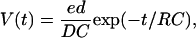
Figs. 3 and 4 show different kinetic features of photovoltage and photocurrent for different flash periods and 20-V external voltage applied across the sample. The flash pulses are also shown in the lower parts of these figures. In Fig. 3, the flash period is 30 s and flash power is 154.1 mW. One can see that the maximum photocurrent density reaches 120 μA/cm2. In Fig. 4, the flash power is 129.0 mW and the flash period is 10 ms, respectively. One can see that these films respond to illumination very fast. Fig. 5 shows the dependence of photovoltage on the flash power. The flash period is 5 s and the external voltage is 20 V. One can see from this figure that the flash power can affect the photovoltage greatly, and a maximum photovoltage as high as 1.72 V is obtained when a flash power P = 170.2 mW is used. In all the figures above, the solid lines indicate the theoretically fit results and the symbols show measured data. Before discussing these results in detail, let us review and develop a theoretical model (Keszthelyi, 1980; Ormos et al., 1983). Let us consider a single oriented bR molecule in a homogeneous sample. An absorbed photon excites a proton to displace a distance d from point 1 to point 2 inside the sample. A voltage V(t) is then created in the external circuit loaded by a capacitance C and the resistance R,
 |
(1) |
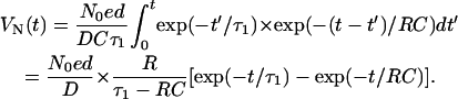
where e is the elementary charge, and D is the distance between two electrodes; in this case, the thickness of the sample. C is the capacitance of the sample, and R = 0.5 MΩ in our measurement setup. In a real experiment, at t = 0, the photons excite the number of protons, N0. Because the excited protons are taken up by the transition from the M-state to the N-state, the number of protons Nt(t) undergoes a simple exponential decay
 |
(2) |
where τ1 is the lifetime of the protons (Ormos et al., 1983). Every excited-proton displacement produces a voltage as given in Eq. (1). To obtain the total voltage VN(t) we have to integrate the V(t) function for all time t′ < t, which means the folding of Eqs. 1 and 2 into
 |
(3) |
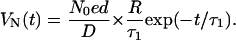
In our case, the area of the metallic electrode is ∼7 mm2, the capacitance is ∼50 pF, and RC ∼25 μs. The lifetime τ1 of the protons is much longer than RC, so Eq. 3 can be simplified to
 |
(4) |
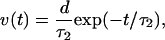
After being excited, protons will be taken up and retrapped in the photochemical cycle. Therefore, the proton velocity v should be a function of time. To describe this process more accurately, let us assume the velocity of the moving protons is
 |
(5) |
where τ2 is the rate constant that describes the proton uptake process (22–24). After taking this effect into account and folding Eqs. 4 and 5, we obtain
 |
(6) |
After the flash power is turned off, the photovoltage and photocurrent decrease quickly. To describe this process, two parameters must be introduced into Eq. 6
 |
(7) |
where A and B are two constants. One can see from Figs. 3–5 that the curves fitted by using this model are essentially in agreement with the experimental measurements, although the flash period varies from 10 ms to 30 s and the flash power varies from 11 mW to 170 mW. Fig. 6 shows the fitted lifetime τ1 (⋄) and uptake rate constant τ2 (○) of excited protons during illumination as functions of flash power. One can see from this figure that the lifetime τ1 is on the order of several tens of thousands of seconds and the rate constant τ2 is ∼104 times smaller than τ1. Also, one can see that τ2 is essentially not affected by the flash power, and that τ1 is significantly dependent on the power. One can infer that τ2 is determined by intrinsic factors of the sample.
FIGURE 3.

Photovoltage and photocurrent as a function of time. An external voltage of 20 V is applied (corresponding electric field: 1.97 × 10⁵ V/m) across the sample. The lower part of this figure shows the laser pulse. The pulse power is 154.1 mW. Symbols show the experimental results and the solid line indicates the fitted result. One can see that the maximum photovoltage and photocurrent intensity reach 3.8 V and 120 μA/cm2, respectively, and the theoretical model gives a good description for the process.
FIGURE 4.

Photovoltage and photocurrent as a function of time. External voltage is 20 V. Flash period is 10 ms. Symbols show the experimental results and the solid line indicates the fitted result. The lower part shows the laser pulse. One can see from this figure that the photovoltage has a quite short response time upon illumination.
FIGURE 5.

Kinetic feature dependence on power under the same external voltage of 20 V and flash period of 5 s. Symbols show the experimental results and the solid lines indicate the fitted results.
FIGURE 6.

The fitted lifetime τ1 (⋄) of excited protons and the rate constant τ2 (○) according to Eq. 7 as a function of the flash power. The external voltage and flash period are 20 V and 5 s, respectively.
In addition to τ1 and τ2, one can obtain the average displacement d of the excited protons during illumination from the curve fit by using Eqs. 6 and 7. By integrating the fitted photocurrent curves with respect to time from the time when the flash power is turned off to the time when the photocurrent decreases to zero, one can obtain the number of protons, Nt, at the time when the flash power is turned off. The results obtained by integrating are shown in Fig. 7. Symbols indicate the results of integrating and the solid lines correspond to the fitted result. The curve fit shows Nt ∼ P1.35, where P stands for the flash power in units of mW. Fig. 8 shows the fitted average displacement of excited protons as a function of the flash power. Unlike the results obtained for suspensions of electric field-oriented PM reported in Keszthelyi and Ormos (1980), in our sample, the average displacement is several tens of micrometers instead of several nanometers. A possible explanation is that our samples are solid films and bR molecules are embedded in a PVA matrix that acts as a proton transport species. Thus the protons can easily hop all around inside the sample by means of hydrogen bonds. In contrast, in oriented liquid samples, the protons can only move within a single fragment (size is approximately several nanometers) of PM since the individual fragments are isolated by solution. This is one of the reasons why we obtain much stronger photocurrents. It is also worthwhile to note that the average displacement only slightly varies with increasing power. This may indicate that the displacement is mainly determined by the composition of the samples.
FIGURE 7.

The number of protons generated at the time when the flash laser is turned off, determined by integrating the fitted photocurrent curves with respect to time, as a function of flash power. Symbols indicate the integrated result and the solid line shows the fitted result. The external voltage is 20 V and flash period is 5 s.
FIGURE 8.

The fitted average displacement of excited protons as a function of flash power according to Eq. 7. One can see that it is only slightly dependent on power. This may indicate that the average displacement is mainly determined by the composition of the sample.
Fig. 9 shows photovoltage and photocurrent intensity as a function of the external field. Symbols indicate the measured results and the solid line corresponds to the fitted result. The flash period and flash power are 10 s and 129.0 mW, respectively. The fitted function is V(mV) ∼ (E0)1.06, where V is photovoltage and E0 is the external field. One can see that the photovoltage increases linearly with the external field for this kind of material. The fitted function is V(mV) ∼ (Δt)0.18, where Δt is the flash period in units of ms. From this figure, one can see that the photovoltage increases functionally more slowly with increasing flash period than with external voltage. Fig. 10 shows photovoltage and photocurrent intensity as a function of the flash period. Symbols indicate the measured results and the solid line corresponds to the fitted result. The flash period and external voltage are 5 s and 20 V, respectively. The fitted function is V(mV) ∼ (P)1.66, where P is the flash power in units of mW. One can see from this fit that of the parameters studied, the photovoltage and photocurrent increase most quickly with increasing flash power. Therefore, increasing the flash power is the most effective method we have identified to obtain high photovoltage and large photocurrent in self-assembled bR films.
FIGURE 9.

Photovoltage and photocurrent as a function of external field. Symbols indicate the measured result and the solid line shows the fitted result.
FIGURE 10.

Photovoltage and photocurrent as a function of flash power. Symbols indicate the measured result and the solid line shows the fitted result.
Considering the potential practical applications of such materials in optoelectronic devices, we used a projector (Fiber-Lite 3100, Dolan-Jenner Industries) as a CW visible light source to illuminate the sample. The output light intensity from this projector is 11.1 W/cm2. No filter was used. For an external voltage of 25 V applied to the sample, and illumination period of 68 s, the kinetics of photovoltage is shown in Fig. 11. Symbols and the solid line indicate the measured and fitted results, respectively. The obtained maximum photovoltage is 2.1 V, corresponding to a photocurrent intensity of 59 μA/cm2. The fitted results according to Eq. 6 give τ1 = 2.36 × 10⁶s and τ2 = 8.79 s. This result shows that the sample materials can also produce a strong photocurrent upon illumination of by regular CW visible light.
FIGURE 11.

Photovoltage as a function of time with CW lamp light illumination. External voltage is 25 V and illumination intensity is 11.1 W/cm2. Symbols indicate the measured result and the solid line shows the fitted result. One can see that the sample also gives strong response to illumination by incoherent light.
CONCLUSIONS
In summary, we have fabricated a novel type of bR/PVA films using a modified sol-gel technique, and have demonstrated their high-performance photovoltaic behavior by using both pulsed laser excitation and regular light illumination methods. In these films, the lifetime of excited protons is extended dramatically to as long as 104s. As a result, the corresponding maximum photovoltage and photocurrent intensities reach 3.8 V and 120 μA/cm2, respectively. Comparing these results with those reported previously, the photocurrent intensity is several tens of times larger. A model has also been developed and used to extract several intrinsic parameters and fit the kinetics of photovoltage and photocurrent. The experimental results agree with the fitted results. The results indicate that protons may be able to hop all over within the films and the average displacement is on the order of several tens of micrometers as well as illumination-intensity dependent. Theoretical fits also show that the photovoltage and photocurrent increase linearly with applied external field, but increase exponentially with flash power.
Acknowledgments
This work has been supported in part by the Optical Science and Engineering Research Center.
References
- Birge, R. R., T. M. Cooper, A. E. Lawrence, M. B. Masthay, C. Vasilakis, C. F. Zhang, and R. Zidovetzki. 1989. A spectroscopic, photocalorimetric, and theoretical investigation of the quantum efficiency of the primary event in bacteriorhodopsin. J. Am. Chem. Soc. 111:4063–4074. [Google Scholar]
- Brauchle, C., N. Hampp, and D. Oesterhelt. 1991. Optical applications of bacteriorhodopsin and its mutated variants. Adv. Mater. 3:420–428. [Google Scholar]
- Butt, H. J., K. Fendler, E. Bamberg, J. Tittor, and D. Oesterhelt. 1989. Aspartic acids 96 and 85 play a central role in the function of bacteriorhodopsin as a proton pump. EMBO J. 8:1657–1663. [DOI] [PMC free article] [PubMed] [Google Scholar]
- Chamorovsky, S. K., E. P. Lukashev, A. A. Kononenko, and A. B. Rubin. 1983. Effects of electric field on the photocycle of bacteriorhodopsin. Biochim. Biophys. Acta. 725:403–406. [Google Scholar]
- Chen, Z., A. Lewis, H. Takei, and L. Nebenzahl. 1991. Bacteriorhodopsin oriented in polyvinyl alcohol films as an erasable optical storage medium. Appl. Opt. 30:5188–5196. [DOI] [PubMed] [Google Scholar]
- Engelman, D. M., R. Henderson, A. D. Mclachlan, and B. A. Wallace. 1980. Path of the polypeptide in bacteriorhodopsin. Proc. Natl. Acad. Sci. USA. 77:2023–2027. [DOI] [PMC free article] [PubMed] [Google Scholar]
- He, J. A., L. Samuelson, L. Li, J. Kumar, and S. K. Tripathy. 1998. Photoelectric properties of oriented bacteriorhodopsin/polycation multilayers by electrostatic layer-by-layer assembly. J. Phys. Chem. B. 102:7067–7072. [Google Scholar]
- He, J. A., L. Samuelson, L. Li, J. Kumar, and S. K. Tripathy. 1999. Bacteriorhodopsin thin film assemblies—immobilization, properties, and applications. Adv. Mater. 11:435–446. [Google Scholar]
- Keszthelyi, L., and P. Ormos. 1980. Electric signals associated with the photocycle of bacteriorhodopsin. FEBS Lett. 109:189–193. [Google Scholar]
- Korenstein, R., and B. Hess. 1977. Hydration effects on the photocycle of bacteriorhodopsin in thin layers of purple membrane. Nature. 184:270–273. [DOI] [PubMed] [Google Scholar]
- Koyama, K., N. Yamaguchi, and T. Miyasaka. 1994. Antibody-mediated bacteriorhodopsin orientation for molecular device architecture. Science. 265:762–765. [DOI] [PubMed] [Google Scholar]
- Koyama, K., N. Yamaguchi, and T. Miyasaka. 1995. Molecular organization of bacteriorhodopsin films in optoelectronic devices. Adv. Mater. 7:590–594. [Google Scholar]
- Lukashev, E. P., E. Vozary, A. A. Kononenko, and A. B. Rubin. 1980. Electric field promotion of the bacteriorhodopsin bR570 to bR412 photoconversion in films of halobacterium halobium purple membrane. Biochim. Biophys. Acta. 592:258–266. [DOI] [PubMed] [Google Scholar]
- Luecke, H., H. T. Richter, and J. K. Lanyi. 1998. Proton transfer pathways in bacteriorhodopsin at 2.3 Å resolution. Science. 280:934–936. [DOI] [PubMed] [Google Scholar]
- Ormos, P., L. Reinisch, and L. Keszthelyi. 1983. Fast electric response signals in the bacteriorhodopsin photocycle. Biochim. Biophys. Acta. 722:471–479. [Google Scholar]
- Ormos, P., Z. Dancshazy, and L. Keszthelyi. 1980. Electric response of a back photoreaction in the bacteriorhodopsin photocycle. Biophys. J. 31:207–213. [DOI] [PMC free article] [PubMed] [Google Scholar]
- Peyroula, E. P., G. Rummel, J. P. Rosenbusch, and E. M. Landau. 1997. X-ray structure of bacteriorhodopsin at 2.5 Å from microcrystals grown in lipidic cubic phase. Science. 277:1676–1681. [DOI] [PubMed] [Google Scholar]
- Robertson, B., and E. P. Lukashev. 1995. Rapid pH change due to bacteriorhodopsin measured with a tin-oxide electrode. Biophys. J. 68:1507–1517. [DOI] [PMC free article] [PubMed] [Google Scholar]
- Schulten, K., and P. Tavan. 1978. A mechanism for the high-driven proton pump of Halobacterium halobium. Nature. 272:85–87. [DOI] [PubMed] [Google Scholar]
- Shen, Y., C. R. Safinya, K. S. Liang, A. F. Ruppert, and K. J. Rothschild. 1993. Stabilization of the membrane protein bacteriorhodopsin to 140°C in two-dimensional films. Nature. 366:48–51. [Google Scholar]
- Shinar, R., M. Ottolenghi, and R. Korenstein. 1977. Electric field effects in bacteriorhodopsin. Biophys. J. 19:1–5. [DOI] [PMC free article] [PubMed] [Google Scholar]
- Song, L., M. A. El-Sayed, and J. K. Lanyi. 1993. Protein catalysis of the retinal subpicosecond photoisomerization in the primary process of bacteriorhodopsin photosynthesis. Science. 261:891–894. [DOI] [PubMed] [Google Scholar]