

Abstract
Fluorescence anisotropy measurements can elucidate the microenvironment of a membrane protein in terms of its rotational diffusion, interactions, and proximity to other proteins. However, use of this approach requires a fluorescent probe that is rigidly attached to the protein of interest. Here we describe the use of one such probe, a green fluorescent protein (GFP) expressed and rigidly held within the amino acid sequence of a major histocompatibility complex (MHC) class I molecule, H2Ld. We contrast the anisotropy of this GFP-tagged MHC molecule, H2LdGFPout, with that of an H2Ld that was GFP-tagged at its C-terminus, H2LdGFPin. Both molecules fold properly, reach the cell surface, and are recognized by specific antibodies and T-cell receptors. We found that polarized fluorescence images of H2LdGFPout in plasma membrane blebs show intensity variations that depend on the relative orientation of the polarizers and the membrane normal, thus demonstrating that the GFP is oriented with respect to the membrane. These variations were not seen for H2LdGFPin. Before transport to the membrane surface, MHC class I associates with the transporter associated with antigen processing complex in the endoplasmic reticulum. The intensity-dependent steady-state anisotropy in the ER of H2LdGFPout was consistent with FRET homotransfer, which indicates that a significant fraction of these molecules were clustered. After MCMV-peptide loading, which supplies antigenic peptide to the MHC class I releasing it from the antigen processing complex, the anisotropy of H2LdGFPout was independent of intensity, suggesting that the MHC proteins were no longer clustered. These results demonstrate the feasibility and usefulness of a GFP moiety rigidly attached to the protein of interest as a probe for molecular motion and proximity in cell membranes.
INTRODUCTION
Fluorescence polarization methods can give information on the formation and size of molecular clusters in living cells. Fluorescence resonance energy transfer (FRET) homotransfer resulting from fluorophore aggregation can be detected through a decrease in fluorescence steady-state anisotropy (Blackman et al., 1998). In addition, polarized fluorescence recovery after photobleaching can resolve molecular rotation (Velez and Axelrod, 1988; Yuan and Axelrod, 1995; Timbs and Thompson, 1990). The rotational diffusion of a membrane protein is proportional to the effective radius squared (Saffman and Delbrük, 1975), which means that even a small change in the effective radius, such as protein dimerization, strongly affects a protein's rotational diffusion. Fluorescence polarization techniques can therefore be used to elucidate the aggregate formation and size of aggregates of appropriate fluorescently tagged molecules, even in cell endomembranes, such as the endoplasmic reticulum (ER).
In this work, we have used fluorescence polarization techniques to analyze the synthesis and assembly of major histocompatibility complex (MHC) class I molecules in the ER (Pamer and Cresswell, 1998). During their assembly MHC class I molecules are retained in the ER through association with chaperones and a complex of proteins including transporter associated with antigen processing (TAP), calnexin, calreticulin, tapasin, and ERp57 (Cresswell et al., 1999). This complex supplies nascent MHC class I with antigenic peptides that are generated in the cytosol by proteosomes. The supply of these peptides results in MHC class I dissociation from the TAP complex, a step that can be detected by measuring lateral diffusion of green-fluorescent-protein-tagged (GFP) MHC I molecules (Marguet et al., 1999), and exit from the ER to the plasma membrane (Suh et al., 1994). Until recently, dissociation from the TAP complex was thought to be the final event for exit of MHC class I from the ER (Suh et al., 1994; Lewis et al., 1996; Neisig et al., 1998). However, recent experiments show that peptide-loaded MHC class I is retained in the ER long enough to exchange for other peptides with more optimal MHC binding (Lewis and Elliott, 1998). Peptide-loaded MHC I molecules then appear to exit the ER by a receptor/carrier-mediated mechanism involving clustering of class I molecules detectable by FRET between cyan- and yellow-fluorescent protein (CFP and YFP)-tagged class I molecules (Marguet et al., 1999; Spiliotis et al., 2000; Pentcheva and Edidin, 2001; Pentcheva et al., 2002).
GFP-tagged MHC class I molecules offer the possibility of elucidating the extent and timing of molecular aggregation. Fluorescence anisotropy can be used to detect clustering by homotransfer FRET (Clayton et al., 2002; Gautier et al., 2001), and to evaluate the size of the clusters in terms of their rotational diffusion (Velez and Axelrod, 1988). To this end, we have compared the fluorescence anisotropies of two different GFP-tagged MHC class I molecules, H2LdGFPin and H2LdGFPout, expressed in L-cells. Both of these are functional proteins, recognized by specific antibodies and by the appropriate T-cell receptor (Marguet et al., 1999). The H2LdGFPin has a GFP attached to its cytoplasmic tail at the C-terminus and is more likely to report on segmental rather than whole protein rotational motion (Hink et al., 2000). The second form of the H2Ld protein, H2LdGFPout, has its GFP within the amino acid sequence of the H2Ld protein. As shown here, this construct holds the GFP rigid relative to the H2Ld protein and thus makes it amenable to polarized fluorescence measurements. In comparison to H2LdGFPin, H2LdGFPout binds the MHC class I light chain, b2m, weakly, and associates poorly with TAP, but it is loaded with peptide and transported out of the ER to the cell surface where it is recognized by specific monoclonal antibodies and by a specific T-cell receptor. In this study, we compare the ways in which GFP reports on MHC class I orientation and environment when it is placed intrasequence or on the C-terminal of the molecule.
MATERIALS AND METHODS
Cells lines and culture
Two separate EGFP-expressing mouse fibroblast cell lines generated previously from L-M(tk−) (H2k) (ATCC CCL 1.3), (Marguet et al., 1999), were used in these studies. These cell lines express two different GFP-tagged forms of the mouse MHC class I allele, H2Ld. One form, H2LdGFPin, was labeled with GFP at the C-terminal cytoplasmic tail of the native protein. The second form, H2LdGFPout, was labeled with GFP placed between the α3- and transmembrane-domains of the native protein (Marguet et al., 1999). In this construct, the GFP is flanked by N- and C-terminal linkers containing six residues (PGSIAT and LGMDEL for N- and C-terminus, respectively). These cells were maintained in RPMI medium (Gibco, Grand Island, NY) supplemented with 2 mM L-glutamine, 10 mM HEPES, and 10% heat-inactivated fetal bovine serum (Gibco), and 300 μg/ml G418. Cos7 cells were maintained in DMEM with 10% heat-inactivated fetal bovine serum. Both cell lines were routinely plated on 35-mm glass bottom dishes (MatTek, Ashland, MA) for polarized confocal laser scanning microscopy. H2LdGFPin and H2LdGFPout cells were incubated overnight at 28°C before observation, which increased H2LdGFPout expression. Cells were placed in imaging buffer containing 125 mM NaCl, 5.7 mM KCl, 2.5 mM CaCl2, 1.2 mM MgCl2, and 10 mM HEPES (pH 7.4) before imaging. MCMV (YPHFMPTNL), a peptide from MCMV pp89 (Reddehase et al., 1989), was made by F-MOC chemical synthesis and then purified by preparative HPLC. MCMV-loading was done overnight by placing the cells in media containing 100 μM MCMV (Marguet et al., 1999). Cells were also routinely treated with 10 μM lactacystin (Kamiya Biomedical, Seattle, WA) in DMEM for 30 min and washed with warm imaging media before experiments (Marguet et al., 1999).
Transient GFP-construct transfections
Cos7 cells were transiently transfected with pEGFP-C1 (BD Biosciences Clontech, Mountain View, CA), pActin-GFP (BD Biosciences Clontech), and epidermal growth factor receptor (pEGFR)-GFP using an ECM 830 BTX square wave electroporator (Genetronics, Sorrento, CA). The cells were transfected with 5 μg of plasmid using ten 50-μs square wave pulses of 300 V with 500-ms intervals. Cells were observed 24–48 h after transfection.
Fluorescence spectroscopy
Fluorescence of GFP solutions was collected on a PTI T-format fluorescence spectrometer running FeliX version 1.42a (Photon Technologies International, Lawrenceville, NJ).
Polarized confocal laser scanning microscopy
Polarized fluorescence images were collected using a Zeiss LSM 410 confocal microscope with a 40 × 1.3 numerical aperture (NA) Plan-NEOFLUAR objective lens (Zeiss, Thornwood, NY). Samples were illuminated by overfilling the back aperture of the objective lens with the 488-nm laser and emission was collected through a 515- to 525-nm bandpass filter. Excitation and emission light passed through rotatable film polarizers placed in the beam path in slots provided by the manufacturer. Images were collected at 0.1-μm/pixel resolution unless otherwise stated. The apparatus g-factor was determined by imaging deep well solutions of fluorescein and GFP. A half-wave plate was used to change the excitation polarization from horizontal to vertical, and the g-factor for the microscope (0.672) was calculated to resolve the equation vv/g × vh = g × hh/hv, determined from the end-on detection geometry (Blackman et al., 1996).
Large NA corrections for confocal anisotropy measurements
Fluorescence anisotropy measurements involve photoselectively exciting the sample with polarized light, and then collecting the emitted fluorescence intensity through polarizers oriented parallel (I‖) and perpendicular (I⊥) to the excitation polarization. Fluorescence anisotropy, r, is conventionally defined as:
 |
(1) |
When observations are made through a high NA objective lens, detection in the parallel and perpendicular direction becomes mixed due to the out-of-plane projections of the emission dipoles (Axelrod, 1979, 1989). In the geometric convention where the z-axis corresponds to the optical axis, leaving the x- and y-axes corresponding to the directions with emission polarizer placed parallel and perpendicular to the excitation polarizer, respectively, the observed intensities are given by:
 |
(2) |
Here, Ix,y,z are the intensities observed through a polarizer oriented along x-, y-, and z-axes, detected through a small aperture, and Ka,b,c are weighting factors that depend on the numerical aperture (exact forms found in Axelrod, 1979). For the limit of 0 NA, Kc = 1, and Ka = Kb = 0. If the fluorophore is randomly oriented, then Iz = Iy, which allows solving for Ix and Iy and calculation of the aperture-corrected, steady-state anisotropy (Axelrod, 1989).
Relative membrane orientation measured using steady-state anisotropy
A model addressing the steady-state fluorescence anisotropy signal of a chromophore as a function of orientation, in a confocal microscope field has been previously described (Blackman et al., 1996). This model describes the determination of the relative orientation of a membrane-associated chromophore from steady-state fluorescence polarization images of spherical membrane samples (red blood cell ghosts). Briefly, this technique utilizes fluorescent polarization images from the cross sections of spherical membrane geometry samples (Fig. 1 A). In these images, the confocal image plane produces a circular sample of the membrane, with the amount of membrane sampled related to the angle between the plane and the full-width at half-maximum of the z-resolution (δ). Images are collected with the emission polarizer perpendicular and parallel to the excitation polarizer. A probe that is oriented relative to the circular membrane demonstrates I‖ and I⊥ intensities that vary with the angle of observation around the circumference of the sampled membrane. These intensity variations are a function of the angle of observation around the membrane, β, the relative angle of the absorption and emission dipoles to the membrane normal, θa and θe (Fig. 1 B), and three correlation functions (C0, C1, and C2). These correlation functions are constrained:
 |
(3) |
The uniaxial rotational diffusion model allows explicit description of these three correlation functions (Blackman et al., 1996). Intensity around the circular membrane varies only if the probe is oriented relative to the membrane.
FIGURE 1.
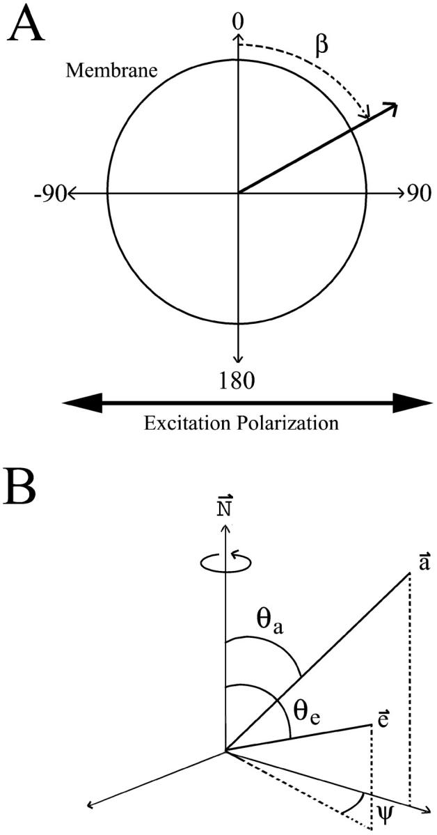
Definition of angles used to describe the geometries obtained from a confocal image of a cell bleb. (A) Image plane of a spherical membrane. Excitation polarizer was kept horizontal while images were collected with emission polarizer parallel and perpendicular to this. Intensity is extracted from these images as a function of the angle around the membrane (β). (B) Parameters used in geometric model. N is the membrane normal axis. The absorption and emission dipole vectors, a and e, are described by the angles between N and the vector (θa and θe) as well as the rotation of e around N(ψ).
The fluorescence intensity around plasma membrane blebs was measured using Scion Image release version beta 3B (Scion, Frederick, MD). Since most blebs were attached to the cell body, it was necessary to digitally exclude regions of blebs touching the cell. The images were filtered with a 5 × 5 Gaussian filter. Measurement of the membrane intensity of the blebs at 10°-membrane tilt angle intervals was done using the “plot radial profiles” macro of Scion Image and selection of the membrane intensity from the maximum of these plots. The intensity from each corresponding membrane tilt angle (β) was then averaged to get an average intensity for each angle (Fig. 1 A). These data were fit using previously described methods to obtain the absorption and emission dipole relative to the membrane normal (Blackman et al., 1996).
Whole cell photobleach measurements
A series of 90 images was collected from the same field of view, with the emission polarizer alternating between the parallel and perpendicular polarization detection for each successive image. The images were each collected in 2.16 s at 0.2-μm/pixel resolution and included 3–10 cells. As the series progressed, the fluorescence in all cells was photobleached (i.e., the imaging laser intensity was sufficient for photobleaching over the timecourse of 90 images). Each successive parallel-perpendicular image pair provided an anisotropy measurement. The intensity for anisotropy calculation was extracted from the ER regions of individual cells using Metamorph Software 4.6 (Universal Imaging, Downington, PA). These bleaching sequences were carried out from 5 to 10 times and involved from 15 to 30 cells for each treatment.
RESULTS
Steady-state anisotropy of GFP
Steady-state fluorescence anisotropy measurements were obtained for various GFP samples (Table 1). Included in this table are spectrometer and confocal microscope measurements of purified GFP in solution as well as confocal microscope measurements of various GFP constructs transiently expressed in cultured fibroblasts. The measurements of purified GFP in solution were done to verify the correction factors used for the high NA lens of the confocal measurement. The anisotropy measured using a fluorescence spectrometer was only slightly larger than that measured on the microscope stage, and both compared well with previous GFP steady-state measurements (Swaminathan et al., 1997; Clayton et al., 2002). Therefore, the correction factors used were adequate to compensate for the high NA of the objective lens.
TABLE 1.
| Anisotropy [r, means ± SE] | ||
|---|---|---|
| GFP in solution | Fluorescence spectrometer | 0.328 ± 0.001 |
| GFP in solution | Confocal microscope | 0.322 ± 0.003 |
| Cellular GFP | Confocal microscope | 0.322 ± 0.004 |
| Cellular Actin-GFP | Confocal microscope | 0.335 ± 0.008 |
| Cellular EGFR-GFP | Confocal microscope | 0.329 ± 0.003 |
The steady-state anisotropies for GFP in solution were measured in cuvette using a fluorescence spectrometer and in deep well dishes using the confocal microscope. All cellular measurements were taken from transient transfections of Cos7 fibroblasts (Materials and Methods).
Previous time-resolved studies have shown that the anisotropy of terminally expressed GFP does not reflect the anisotropy of the whole protein (Hink et al., 2000). It was decided to examine the effect this segmental motion has on the steady-state anisotropy of GFP when expressed in cells either individually or as a terminal-end construct. No difference in steady-state anisotropy was observed between purified GFP in solution and GFP expressed alone in the cell. Also, the steady-state anisotropy of GFP was only slightly increased when expressed in cells as a terminal-end construct with actin (Cellular Actin-GFP) or EGF receptor (Cellular EGFR-GFP). The significant steady-state anisotropy of GFP in solution (0.32) indicates that this fluorophore has a large rotational correlation time, which limits the dynamic range available for measuring changes in steady-state anisotropy (0.32–0.4). Regardless, these data agree with previous results that indicate the link between the GFP reporter and its construct-protein is not rigid, and this probe reports on segmental motion of the protein when expressed at the C- or N-terminus.
Orientation-dependent fluorescence
Two cell lines expressing MHC class I constructs were used with GFP either attached at the C-terminus, H2LdGFPin; or internally between the α3- and transmembrane-domains of the native protein, H2LdGFPout (Marguet et al., 1999). These cells were induced to form plasma membrane blebs using 1 mM H2O2 in imaging buffer (Tank et al., 1982). These blebs were stable and formed a spherical membrane geometry (5.9 ± 0.3 μm radius) lacking internal fluorescence. The chromophore orientation relative to the membrane normal was examined to determine whether intrasequence expression of the GFP tag rigidly attached the probe to the MHC class I protein (Materials and Methods). It was expected that the GFP moiety of H2LdGFPin would show segmental motion, so its anisotropy served as a limited case comparison to the anisotropy of H2LdGFPout. Shown in Fig. 2 are representative polarized fluorescence confocal images of H2LdGFPin (Fig. 2, A, C, and E) and of H2LdGFPout (Fig. 2, B, D, and F). In these images the excitation polarization was kept horizontal (h) and the emission polarizer was set at either horizontal (hh or ‖; Fig. 2, A and B) or vertical (hv or ⊥; Fig. 2, C and D). The intensity around the H2LdGFPin blebs appeared to be uniform in both the hh- and hv-images (Fig. 2, A and C). In contrast, the intensity in the hh-image of the H2LdGFPout (Fig. 2 B) varied with the angle (β) around the membrane bleb. This variation in intensity can be observed in the pseudocolor overlap of the polarized images, shown with emission horizontal (hh, green) and vertical (hv, red) (Fig. 2, E and F). In these pseudocolor images, the H2LdGFPin color varies little around the cell bleb (Fig. 2 E), but in contrast the H2LdGFPout color shows a capping of red (minimum) and green (maximum) fluorescence (Fig. 2 F). Intensity around these membranes was measured at 10° intervals in >100 blebs for each construct (Fig. 3). The H2LdGFPin images demonstrated uniform intensity around the blebs, which is consistent with a random orientation of the GFP relative to the membrane (Fig. 3 A). In contrast, the intensity varied significantly around the blebs of H2LdGFPout cells (Fig. 3 B). This shows that the GFP of the H2LdGFPout molecule is oriented relative to the membrane.
FIGURE 2.
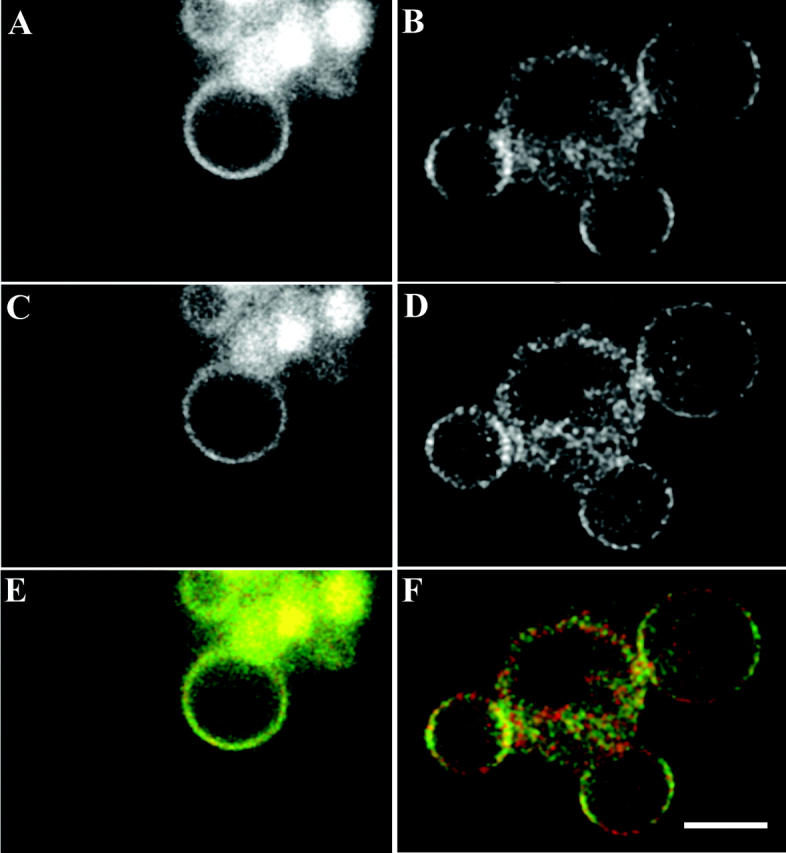
Fluorescence polarization images of H2LdGFPin and H2LdGFPout cell blebs. The excitation polarizer was kept horizontal for the collection of these images. These images were collected on H2LdGFPin (A, C, and E) and H2LdGFPout (B, D, and F) cells that were induced to bleb using 1 mM H2O2. The emission polarizer was placed parallel (hh) for the collection of A and B. The emission polarizer was placed perpendicular (hv) for the collection of C and D. These images are also shown superimposed upon one another with pseudocolored green (hh) and red (hv). The bar shown in F is 5 μm.
FIGURE 3.

Fluorescence polarization intensities obtained from the periphery of cell blebs. Intensity was extracted at 10° increments from >100 membrane blebs for both H2LdGFPin (A) and H2LdGFPout (B). The H2LdGFPout intensity varied substantially in both the Ihh and Ihv images and this allowed least-squares analysis fitting using the model described (Materials and Methods). Error bars indicate the standard error of the mean for each angle (β) measured.
The intensity variance observed with H2LdGFPout was fit to the orientation model described (Materials and Methods). The fit to this model provided the angle relative to the membrane normal of the absorbance and emission dipoles (± the 95% confidence interval): θa (49 ± 0.7°) and θe (52 ± 1.5°). Therefore, this data indicates that the GFP of H2LdGFPout is rigidly oriented to the membrane with its absorption and emission dipoles being relatively close to one another (∼3°).
Peptide loading of H2LdGFP in cells
Since the GFP moiety of H2LdGFPout had a rigid orientation to the membrane, the anisotropy of this reporter was likely to reflect the rotational mobility of the whole molecule. To test whether the GFP was rigid to the protein, we used the peptide MCMV (YPHFMPTNL) (Reddehase et al., 1989), whose affinity for H2Ld is ∼109 M−1. When exogenously given to cells, MCMV-peptide binds to MHC class I molecules in the ER. After binding, the peptide-loaded MHC class I molecules then traffic to the membrane surface (Day et al., 1997; Marguet et al., 1999). If the GFP was rigidly attached to its construct protein, any changes in environment as it traffics to the plasma membrane were likely to be reflected in anisotropy changes. Such anisotropy changes thus reflect the environment of the whole molecule. Fluorescence intensity measurements were carried out using the confocal microscope, which permits specific intensity measurements from the ER regions of individual cells. For comparison, these studies were done in parallel with H2LdGFPin. Shown in Fig. 4 are the scatter plots of the steady-state anisotropy of H2LdGFP for individual cells plotted against the average total intensity (I⊥,‖) of ER fluorescence. The average steady-state anisotropy is also indicated at the bottom right of each panel (summarized in Table 2). MCMV treatment caused no detectable change in the anisotropy of the H2LdGFPin cells (Fig. 4, A and B). In contrast, the steady-state anisotropy of the MCMV-treated H2LdGFPout cells was significantly larger than untreated (Fig. 4, C and D). This change is consistent with a rigid attachment between GFP and H2Ld. None of the four anisotropies showed a significant dependence on the total average intensity (I⊥,‖) suggesting that there was no significant FRET between randomly distributed molecules. However, the steady-state anisotropy of H2LdGFPout, without added peptide, was significantly lower than the anisotropy of H2LdGFPin. Therefore, although our data indicate that concentration-dependent (nonspecific) homotransfer did not occur, the lower-than-expected steady-state anisotropy strongly suggested homotransfer FRET between clustered molecules. This FRET is almost completely abolished after feeding peptide to the cells.
FIGURE 4.

Steady-state fluorescence anisotropy obtained from the ER of H2LdGFPin (A and B) and H2LdGFPout (C and D). The anisotropy was calculated using the correction factors described (Materials and Methods) from intensities extracted from confocal images. The intensities were extracted from individual cells from regions thought to be the ER. MCMV treatment was done at a concentration of 100 μg/ml in cell media overnight (B and D). In the bottom right corner is the average steady-state anisotropy measured (mean ± SE) from H2LdGFPin (N = 262), H2LdGFPin + MCMV (N = 318), H2LdGFPout (N = 196), and H2LdGFPout + MCMV (N = 212).
TABLE 2.
| H2LdGFPout Anisotropy [r, mean ± SE] | H2LdGFPin Anisotropy [r, mean ± SE] | |
|---|---|---|
| ER | 0.333 ± 0.003 | 0.340 ± 0.002 |
| ER after MCMV loading | 0.348 ± 0.002 | 0.343 ± 0.002 |
| Membrane blebs | 0.340 ± 0.003 | 0.346 ± 0.004 |
This chart summarizes the steady-state anisotropy found in various figures and is presented to aid comparison between these values. The Membrane blebs anisotropy is calculated from the values shown in Fig. 3.
Photobleaching measurements
Whole cell photobleaching experiments were carried out to test for the occurrence of cluster-dependent homotransfer. The aim was to gradually bleach each cell's GFP so that if clusters of MHC I were present, the number of active GFP labels per cluster would decrease, thus decreasing homotransfer and increasing the observed anisotropy. In these studies, groups of 3–10 cells were progressively photobleached while collecting successive parallel and perpendicular polarization images (Materials and Methods). Since the time between images is short (∼6 s) and the whole cell is bleached, it is unlikely that there is any cycling of the H2LdGFPin/out between plasma membrane and ER membranes. Shown in Fig. 5 is the steady-state anisotropy versus the intensity remaining after photobleaching for H2LdGFPin (Fig. 5, A and B) and H2LdGFPout (Fig. 5, C and D) in the absence (Fig. 5, A and C) and presence (Fig. 5, B and D) of MCMV peptide. The fit to the y-intercept is interpreted as the null homotransfer steady-state anisotropy or the expected steady-state anisotropy in the absence of homotransfer. In these curves, the steeper the absolute slope, the greater is the dependence of anisotropy on homotransfer. The H2LdGFPin curves in the presence and absence of MCMV peptide look similar and yield nearly identical null homotransfer anisotropies (Fig. 5, A and B). These data suggest that the H2LdGFPin anisotropy is unaffected by homotransfer FRET, since the total change in r with intensity is <4%. In contrast, the data for H2LdGFPout show clear differences between the steady-state and the peptide-loaded population (Fig. 5, C and D). At steady state, H2LdGFPout anisotropy exhibited more homotransfer than anisotropy of H2LdGFPout loaded with MCMV peptide (12% change in r with I versus 3% change for peptide-loaded molecules). However, the anisotropies for the limit of no FRET are identical within error. The limiting anisotropy of H2LdGFPin was smaller than that of H2LdGFPout, which is in agreement with the previous conclusion that the GFP moiety of the H2LdGFPout rigidly attached to the MHC class I protein. Therefore, the low H2LdGFPout anisotropy is likely due to cluster-dependent homotransfer FRET in the ER membrane.
FIGURE 5.

Controlled bleach experiments of H2LdGFPin and H2LdGFPout cells. Images were collected sequentially as described (Materials and Methods), which resulted in gradual bleaching of the GFP fluorescence. Bleach measurements were done on H2LdGFPin (A, N = 5), H2LdGFPin + MCMV (B, N = 5), H2LdGFPout (C, N = 5), and H2LdGFPout + MCMV (D, N = 10). N represents the number of fields of view used in each bleach curve and each field of view contained from 3–6 cells. These curves were fit linearly and the y-intercept is shown in the bottom left of each graph (± 95% confidence interval). This value is referred to as the null homotransfer anisotropy.
MHC class I molecules form ternary complexes with calnexin and TAP and undergo peptide-regulated interaction with TAP via their extracellular domains (Suh et al., 1996; Bai and Forman, 1997). The effect of the proteasome inhibitor lactacystin on the presentation of TAP-dependent and TAP-independent peptide epitopes by class I molecules (Bai and Forman, 1997) stops the trafficking of MHC class I molecules at the TAP complex. Previous diffusion measurements of H2LdGFPout indicated an association with the TAP complex after Lactacystin treatment (Marguet et al., 1999). Hence, lactacystin-treated cells provide a measure of the anisotropy of the TAP-associated MHC class I. Shown in Fig. 6 are the bleach curves for H2LdGFPout with and without lactacystin treatment. There is no discernable difference between the two curves, which suggests that the homotransfer observed with H2LdGFPout is due to a self-association at the TAP complex.
FIGURE 6.

Controlled bleach experiment with lactacystin-treated H2LdGFPout cells. Images were collected sequentially as described (Materials and Methods), which resulted in gradual bleaching of the GFP fluorescence. Bleach measurements were done on H2LdGFPout (▪, N = 5) and H2LdGFPout + lactacystin treatment (•, N = 10).
DISCUSSION
The segmental motion of terminally linked GFP constructs limits their use in fluorescence anisotropy experiments (Hink et al., 2000). To address this issue, we examined the steady-state anisotropies of constructs with GFP placed either C-terminally (H2LdGFPin) or intrasequence (H2LdGFPout) of the MHC class I membrane protein. In contrast to H2LdGFPin, H2LdGFPout was rigidly oriented to the membrane, and demonstrated changes in steady-state anisotropy initiated by MCMV-peptide loading. To our knowledge, this is the first demonstration of a rigid attachment between GFP and its protein construct.
The polarized fluorescence intensity around plasma membrane blebs was uniform for H2LdGFPin but varied for H2LdGFPout (Fig. 2). This result indicates that the relative membrane orientation of the GFP reporter is random for H2LdGFPin and rigid for H2LdGFPout. Fitting the H2LdGFPout intensity variations provided nearly co-linear absorption (49° ± 0.7) and emission (52° ± 1.5) dipoles. The initial anisotropy (r0) of any fluorophore decreases from 0.4 as the angle between absorption and emission dipoles increases. Therefore, the closeness of the fitted angles agrees with previous studies, which have shown the r0 of GFP to be nearly 0.4 (Volkmer et al., 2000). These data are all consistent with the GFP moiety of H2LdGFPin being randomly oriented relative to the membrane, and the GFP of H2LdGFPout adopting a more constrained orientation. This rigidity is likely due to the constraints placed on both the N- and C-terminus of the GFP. It is not clear if this rigidity is due to short linker sequences (six residue linkers on both ends) or direct interaction between GFP and the membrane. However, it is likely that the rigidity of this attachment would decrease with increased linker length.
We observed no change in the steady-state anisotropy of H2LdGFPin after MCMV peptide loading (Fig. 4). This is consistent with the C-terminal GFP of H2LdGFPin not fully reporting the environment of the H2Ld molecule. Previous FRET measurements suggest that peptide-loaded C-terminally tagged MHC class I molecules are clustered as they are staged for ER exit (Pentcheva and Edidin, 2001). This difference may arise because different MHC class I molecules were used in the two sets of experiments, and were expressed in different cells. The earlier work was done with human MHC class I molecules, HLA-A2, expressed in HeLa cells, whereas the present study is of mouse MHC class I molecules expressed in mouse L-cells. This difference may also arise due to differences between the two experimental methods and their ability to detect FRET (anisotropy changes versus acceptor photobleaching). In particular, the CFP-YFP heterotransfer used in the previous studies has a slightly larger Forster distance (4.92 ± 0.10 nm) than the GFP-GFP homotransfer used in these studies (4.65 ± 0.09 nm) (Patterson et al., 2000). Such a difference is likely to have reduced our chances of observing any H2LdGFPin homotransfer FRET.
The H2LdGFPout steady-state anisotropy was more homotransfer-dependent than H2LdGFPin and increased in response to MCMV-peptide loading (Fig. 5). The change in H2LdGFPout anisotropy is consistent with a rigid attachment between GFP and H2Ld. The differences between H2LdGFPout and H2LdGFPin indicate that these two probes are either behaving dissimilarly in the cell (reporting on different regions) or that the placement of the GFP moiety on MHC class I modifies the donor-acceptor distance. Resonance energy transfer efficiency is strongly affected by changes in the donor-acceptor distance on the order of a typical globular protein (20–40 Å). Hence, it is important to note that placement of the GFP intrasequence of a protein can offer alternatives to end-terminal labeling. It is also intriguing to speculate that the Forster distance (R0) of H2LdGFPout increased due to its rigid attachment, arising because of a better relative orientation factor (κ2) between donor and acceptor dipoles. However, this is unlikely since only the most rigid probes demonstrate a κ2 that deviates from two-thirds (van der Meer, 1999). Therefore, the changes in H2LdGFPout anisotropy likely reflect the fact that the GFP held rigidly within the H2Ld molecule reports the changes in its neighbors and environment as it matures through the ER.
The observed H2LdGFPout homotransfer indicates that this protein is aggregated in the ER, and the decrease in its homotransfer after peptide loading suggests a dispersal of these aggregates. Lactacystin treatment did not alter the observed homotransfer (Fig. 6), which is consistent with this clustering occurring at the TAP complex. This is in contrast to previous FRAP and FRET measurements that indicate MHC class I molecules cluster as they are staged for ER exit (Pentcheva and Edidin, 2001). In comparison to H2LdGFPin, H2LdGFPout binds to the MHC class I light chain, b2m, weakly, and associates poorly with TAP. However, these differences are unlikely to account for the observed FRET behavior, inasmuch as an HLA-A2 mutant that also does not associate with TAP does cluster after peptide loading (Pentcheva and Edidin, 2001). It is also possible that the lack of detectable FRET after peptide loading is due to the lowered technique sensitivity and the decreased GFP-GFP Forster distance compared to CFP-YFP (as suggested previously for the lack of H2LdGFPin FRET detection). However, this would dictate that the TAP associated FRET observed with H2LdGFPout occurs due to optimal geometric positioning of the GFP. This would only fit our data if the optimal positioning of H2LdGFPout at the TAP complex resulted in C-terminal separation that does not allow the detection of H2LdGFPin homotransfer FRET. Clearly, our results open the way for further experiments—for example, polarization FRAP that can further define the environment of nascent MHC class I molecules. Such experiments will be needed to resolve the differences between the results reported here and earlier work using hetero-FRET to detect clusters of class I molecules.
Acknowledgments
The authors thank S.M. Blackman for helpful discussion relating to data analysis. The pEGFR-EGFP was a kind gift from J. Staros.
This work was supported by National Institutes of Health grants DK53434 and CA86283 to D.W.P., and AI-14584 to M.E.; and a National Science Foundation grant DBI-9871063 to D.W.P. A National Institutes of Health Individual National Research Service Award, DK59737, also supported J.V.R. Steady-state anisotropy imaging was performed, in part, through the use of the Vanderbilt University Medical Center Cell Imaging Core Resource, which is supported by National Institutes of Health grants CA68485 and DK20593.
References
- Axelrod, D. 1979. Carbocyanine dye orientation in red cell membrane studied by microscopic fluorescence polarization. Biophys. J. 26:557–573. [DOI] [PMC free article] [PubMed] [Google Scholar]
- Axelrod, D. 1989. Fluorescence polarization microscopy. Methods Cell Biol. 30:333–352. [PubMed] [Google Scholar]
- Bai, A., and J. Forman. 1997. The effect of the proteasome inhibitor lactacystin on the presentation of transporter associated with antigen processing (TAP)-dependent and TAP-independent peptide epitopes by class I molecules. J. Immunol. 159:2139–2146. [PubMed] [Google Scholar]
- Blackman, S. M., C. E. Cobb, A. H. Beth, and D. W. Piston. 1996. The orientation of eosin-5-maleimide on human erythrocyte band 3 measured by fluorescence polarization microscopy. Biophys. J. 71:194–208. [DOI] [PMC free article] [PubMed] [Google Scholar]
- Blackman, S. M., D. W. Piston, and A. H. Beth. 1998. Oligomeric state of human erythrocyte band 3 measured by fluorescence resonance energy homotransfer. Biophys. J. 75:1117–1130. [DOI] [PMC free article] [PubMed] [Google Scholar]
- Clayton, A. H., Q. S. Hanley, D. J. Arndt-Jovin, V. Subramaniam, and T. M. Jovin. 2002. Dynamic fluorescence anisotropy imaging microscopy in the frequency domain (rFLIM). Biophys. J. 83:1631–1649. [DOI] [PMC free article] [PubMed] [Google Scholar]
- Cresswell, P., N. Bangia, T. Dick, and G. Diedrich. 1999. The nature of the MHC class I peptide loading complex. Immunol. Rev. 172:21–28. [DOI] [PubMed] [Google Scholar]
- Day, P. M., J. W. Yewdell, A. Porgador, R. N. Germain, and J. R. Bennink. 1997. Direct delivery of exogenous MHC class I molecule-binding oligopeptides to the endoplasmic reticulum of viable cells. Proc. Natl. Acad. Sci. USA. 94:8064–8069. [DOI] [PMC free article] [PubMed] [Google Scholar]
- Gautier, I., M. Tramier, C. Durieux, J. Coppey, R. B. Pansu, J. C. Nicolas, K. Kemnitz, and M. Coppey-Moisan. 2001. Homo-FRET microscopy in living cells to measure monomer-dimer transition of GFT-tagged proteins. Biophys. J. 80:3000–3008. [DOI] [PMC free article] [PubMed] [Google Scholar]
- Hink, M. A., R. A. Griep, J. W. Borst, A. van Hoek, M. H. Eppink, A. Schots, and A. J. Visser. 2000. Structural dynamics of green fluorescent protein alone and fused with a single chain Fv protein. J. Biol. Chem. 275:17556–17560. [DOI] [PubMed] [Google Scholar]
- Lewis, J. W., A. Neisig, J. Neefjes, and T. Elliott. 1996. Point mutations in the α2 domain of HLA-A2.1 define a functionally relevant interaction with TAP. Curr. Biol. 6:873–883. [DOI] [PubMed] [Google Scholar]
- Lewis, J. W., and T. Elliott. 1998. Evidence for successive peptide binding and quality control stages during MHC class I assembly. Curr. Biol. 8:717–720. [DOI] [PubMed] [Google Scholar]
- Marguet, D., E. T. Spiliotis, T. Pentcheva, M. Lebowitz, J. Schneck, and M. Edidin. 1999. Lateral diffusion of GFP-tagged H2Ld molecules and of GFP-TAP1 reports on the assembly and retention of these molecules in the endoplasmic reticulum. Immunity. 11:231–240. [DOI] [PubMed] [Google Scholar]
- Neisig, A., C. J. Melief, and J. Neefjes. 1998. Reduced cell surface expression of HLA-C molecules correlates with restricted peptide binding and stable TAP interaction. J. Immunol. 160:171–179. [PubMed] [Google Scholar]
- Pamer, E., and P. Cresswell. 1998. Mechanisms of MHC class I-restricted antigen processing. Annu. Rev. Immunol. 16:323–358. [DOI] [PubMed] [Google Scholar]
- Patterson, G. H., D. W. Piston, and B. G. Barisas. 2000. Forster distances between green fluorescent protein pairs. Anal. Biochem. 284:438–440. [DOI] [PubMed] [Google Scholar]
- Pentcheva, T., and M. Edidin. 2001. Clustering of peptide-loaded MHC class I molecules for endoplasmic reticulum export imaged by fluorescence resonance energy transfer. J. Immunol. 166:6625–6632. [DOI] [PubMed] [Google Scholar]
- Pentcheva, T., E. T. Spiliotis, and M. Edidin. 2002. Cutting edge: tapasin is retained in the endoplasmic reticulum by dynamic clustering and exclusion from endoplasmic reticulum exit sites. J. Immunol. 168:1538–1541. [DOI] [PubMed] [Google Scholar]
- Reddehase, M. J., J. B. Rothbard, and U. H. Koszinowski. 1989. A pentapeptide as minimal antigenic determinant for MHC class I-restricted T-lymphocytes. Nature. 337:651–653. [DOI] [PubMed] [Google Scholar]
- Saffman, P. G., and M. Delbrük. 1975. Brownian motion in biological membranes. Proc. Natl. Acad. Sci. USA. 72:3111–3113. [DOI] [PMC free article] [PubMed] [Google Scholar]
- Spiliotis, E. T., H. Manley, M. Osorio, M. C. Zuniga, and M. Edidin. 2000. Selective export of MHC class I molecules from the ER after their dissociation from TAP. Immunity. 13:841–851. [DOI] [PubMed] [Google Scholar]
- Suh, W. K., M. F. Cohen-Doyle, K. Fruh, K. Wang, P. A. Peterson, and D. B. Williams. 1994. Interaction of MHC class I molecules with the transporter associated with antigen processing. Science. 264:1322–1326. [DOI] [PubMed] [Google Scholar]
- Suh, W. K., E. K. Mitchell, Y. Yang, P. A. Peterson, G. L. Waneck, and D. B. Williams. 1996. MHC class I molecules form ternary complexes with calnexin and TAP and undergo peptide-regulated interaction with TAP via their extracellular domains. J. Exp. Med. 184:337–348. [DOI] [PMC free article] [PubMed] [Google Scholar]
- Swaminathan, R., C. P. Hoang, and A. S. Verkman. 1997. Photobleaching recovery and anisotropy decay of green fluorescent protein GFP-S65T in solution and cells: cytoplasmic viscosity probed by green fluorescent protein translational and rotational diffusion. Biophys. J. 72:1900–1907. [DOI] [PMC free article] [PubMed] [Google Scholar]
- Tank, D. W., E. S. Wu, and W. W. Webb. 1982. Enhanced molecular diffusibility in muscle membrane blebs: release of lateral constraints. J. Cell Biol. 92:207–212. [DOI] [PMC free article] [PubMed] [Google Scholar]
- Timbs, M. M., and N. L. Thompson. 1990. Slow rotational mobilities of antibodies and lipids associated with substrate-supported phospholipid monolayers as measured by polarized fluorescence photobleaching recovery. Biophys. J. 58:413–428. [DOI] [PMC free article] [PubMed] [Google Scholar]
- van der Meer, B. W. 1999. Orientational aspects in pair energy transfer. In Resonance Energy Transfer. D. L. Andrews, and A. A. Demidov, editors. Wiley, New York.
- Velez, M., and D. Axelrod. 1988. Polarized fluorescence photobleaching recovery for measuring rotational diffusion in solutions and membranes. Biophys. J. 53:575–591. [DOI] [PMC free article] [PubMed] [Google Scholar]
- Volkmer, A., V. Subramaniam, D. J. Birch, and T. M. Jovin. 2000. One- and two-photon excited fluorescence lifetimes and anisotropy decays of green fluorescent proteins. Biophys. J. 78:1589–1598. [DOI] [PMC free article] [PubMed] [Google Scholar]
- Yuan, Y., and D. Axelrod. 1995. Subnanosecond polarized fluorescence photobleaching: rotational diffusion of acetylcholine receptors on developing muscle cells. Biophys. J. 69:690–700. [DOI] [PMC free article] [PubMed] [Google Scholar]