Abstract
A covalent dimer of alamethicin Rf30 was synthesized by linking the N-termini by a disulfide bond. When the dimer peptides were added to the cis-side of a diphytanoyl PC membrane, macroscopic channel current was induced only at cis positive voltages. The single-channel recordings showed several conductance levels that were alternately stabilized. These results indicate that the dimer peptides form stable channels by N-terminal insertion like alamethicin and that most of the pores are assembled from even numbers of helices. Taking advantages of the long open duration of the dimer peptide channels, the current-voltage (I-V) relations of the single-channels were obtained by applying fast voltage ramps during the open states. The I-V relations showed rectification, such that current from the cis-side toward the trans-side is larger than that in the opposite direction. The intrinsic rectification is mainly attributed to the macro dipoles of parallel peptide helices surrounding a central pore.
INTRODUCTION
Alamethicin, a 20-residue antibiotic peptide, forms voltage-gated ion channels in bilayer lipid membranes, which have been extensively investigated since Mueller and Rudin (1968) reported “artificial membrane excitability” induced by alamethicin (for reviews, see Latorre and Alvarez, 1981; Sansom, 1991; Woolley and Wallace, 1992; Cafiso, 1994; Duclohier and Wrólewski, 2001). The electrical properties of the channels suggested that alamethicin helices form parallel bundles by inserting their N-termini into the membrane under sufficient applied voltages (Vodyanoy et al., 1983; Hall et al., 1984). Because the helix-bundle structure is a motif of the pore structures in biological ion channels, alamethicin channels are available as a simple model for biological channels. In contrast to biological ion channels, however, alamethicin channels show several different conductance levels that are due to transient changes in number of alamethicin molecules in a helix bundle. The multi-conductance behavior, which merits studying pore size effects on ion channel properties, complicates the analysis of the channels. Further, the voltage-dependent channel formation, which is of interest in connection with gating in biological channels, prevents characterizing the current-voltage relation of single channels.
The above drawbacks of alamethicin channels as a model of biological channels can be overcome by introducing special covalent and noncovalent linkages between alamethicin molecules, which restrict the number of helices forming a channel (You et al., 1996; Jaikaran et al., 1997; Matsubara et al., 1996; Nagaoka et al., 1996a; Duclohier et al., 1999; Futaki et al., 2001). The tethering also prolongs the duration of open channels, which allows measurement of the intrinsic I-V relations of single channels by applying fast voltage ramps during the open states. Woolley and his colleges succeeded to elucidate the intrinsic rectification of single channels formed by covalent dimers of alamethicin (Woolley et al., 1997; Jaikaran et al., 1997).
Most of tethered alamethicins synthesized so far were C-terminally connected by linear and cyclic linkers (You et al., 1996; Jaikaran et al., 1997; Matsubara et al., 1996; Duclohier et al., 1999). The C-terminal modification is likely favorable to less restricted channel formation because the C-terminus of alamethicin is not inserted into the membrane by voltage activation and the C-terminal half is more flexible than the N-terminal one. However, the C-terminally linked dimers do not have the C-terminal α-aminoalcohol that could be important for stable channel formation (Duclohier et al., 1989; Koide et al., 1997), and those need relatively longer linkers because the pore mouth at the C-terminal side is supposed to be wider than that at the N-terminal side (Fox and Richards, 1982). Hence, it is worthwhile to examine whether N-terminally linked dimers form stable channels without interfering with the normal channel formation.
In this paper, we synthesized a covalent dimer of alamethicin that was N-terminally linked by a disulfide bond. The channels formed by the covalent dimer peptides in bilayer lipid membranes were characterized by microscopic and macroscopic channel current measurements.
MATERIALS AND METHODS
Peptide synthesis
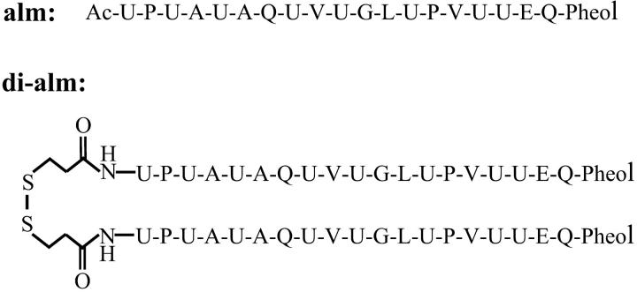
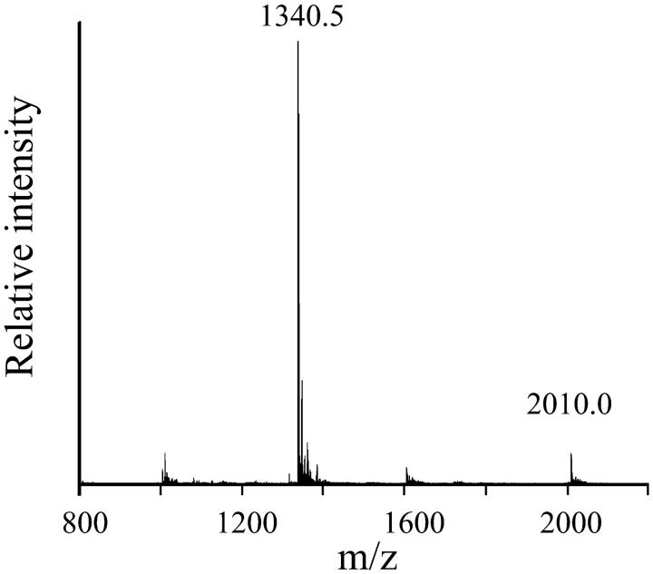
Fig. 1 shows the sequences of the peptides synthesized in this study. Alamethicin Rf30 (alm) was synthesized by a solid-phase technique with Fmoc amino acid fluorides (Wenschuh et al., 1995). The details were described in a previous paper (Asami et al., 2002). After completion of the assemblage of amino acids on the resin, the N-terminal Fmoc-group was deprotected and the resin was separated into two portions. One portion of the resin was treated with acetic anhydride to protect the N-termini of the peptides with acetyl group and then the peptides were cleaved from the resin to obtain alm. Peptides on the other portion of the resin were further condensed with S-acetamidomethyl-β-mercaptopropionic acid synthesized as described in a previous paper (Marbach and Rudinger, 1974) or purchased from Peptide International (Louisville, KY) and then were cleaved from the resin. This peptide (acm-mp-alm) and alm were purified by gel-chromatography on a LH-20 column and then by reverse-phase HPLC on a YMC-ODS column with elutes containing 63–68% CH3CN, 37–32% H2O, and 0.05% TFA. Treatment of the purified acm-mp-alm with 0.025 M I2 in 70–80% CH3CN/H2O removed the acm-group and made a disulfide linkage of the peptides to obtain di-alm. The di-alm was purified by gel-chromatography on a LH-20 column. The purified alm and di-alm were characterized by electrospray ionization mass spectroscopy (ESI-MS) using an API-3000K (Perkin-Elmer Sciex, Wellesley, MA) as: m/z 982.7 [M + 2H+] and 655.1 [M + 3H+] for alm (MW = 1963.3); 2010.0 [M + 2H+], 1340.5 [M + 3H+] for di-alm (MW = 4018.79). Fig. 2 shows the ESI-MS chart of the purified di-alm.
FIGURE 1.
Amino acid sequences of alamethicin Rf30 and its dimer N-terminally linked by a disulfide bond. U, α-aminoisobutyric acid; Pheol, phenylalaninol; Ac, acetyl.
FIGURE 2.
ESI-MS chart of purified di-alm.
Channel current measurements
Currents through ion channels formed by alm and di-alm in diphytanoyl phosphatidylcholine bilayers were measured as described previously (Nagaoka et al., 1996b; Koide et al., 1997; Asami et al., 2002). The bathing solution was 1 M KCl buffered with either 10 mM MES-HCl (pH 3.5) or 10 mM HEPES-KOH (pH 6.9–7.0). A pair of Ag-AgCl electrodes was used for current measurement and voltage supply. Peptides were added to one of the two aqueous compartments (cis-side) to a final concentration of 1–5 nM for alm and 0.1–2.5 nM for di-alm, and the other side (tran-side) is virtually grounded. Currents were measured using a homemade current-voltage converter or a 1211 Current Amplifier (ITHACO, Ithaca, NY). The output voltages of the current-voltage converter and the applied voltages to the membrane were recorded with a DR-F2a Digital Recorder (TEAC, Tokyo, Japan). Measurements were made at 25 ± 0.5°C. Single-channel recordings were made by carefully adjusting DC voltage not to count multiple channels in a membrane and the cutoff frequency was ∼1 kHz. For macroscopic current measurements, triangular wave voltages of frequencies of 1 mHz to 1 Hz or step voltages were applied to the membranes.
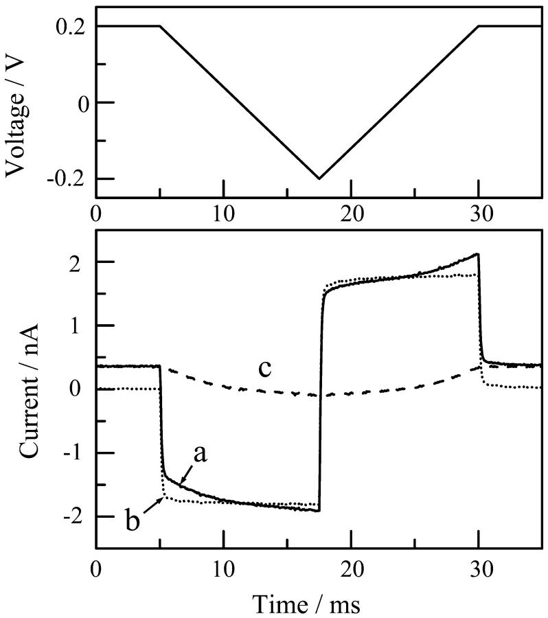
The current-voltage characteristics of the single channels of di-alm were measured by applying fast voltage ramps (the sweep rate was 32 mV/ms) in addition to a DC voltage during the open states, as described previously (Kienker et al., 1994; Kienker and Lear, 1995). Fig. 3 shows an example of the measurements. The current trace (curve a) obtained when a voltage ramp was applied to a channel in the open state includes a membrane charging current that can be estimated from the current measured in the closed state (curve b). The net channel current (curve c) was, therefore, obtained by subtracting curve b from curve a.
FIGURE 3.
Current responses to a fast voltage ramp in open (curve a) and closed (curve b) states. Curve c is the net channel current obtained by subtracting curve b from curve a. Measurement was made for the level-2 channel of di-alm in 1 M KCl at pH6.9.
Theoretical calculation of single-channel current
The current-voltage relations of single alamethicin channels were calculated using the macroscopic channel model shown in Fig. 6 in a previous paper (Asami et al., 2002). In the model, the relative permittivity was assumed to be 80 for the pore interior and the aqueous phase and 2 for the pore wall and the membrane. Electrolytes are excluded from the central part of the pore. The dipole moments of peptide-helix backbones and the charges of Glu-18 were taken into account. The energy barrier profiles of permeating ions in a pore were calculated by an axial symmetric finite-difference Poisson-Boltzmann method. The single-channel currents were calculated using the generalized Nernst-Planck equation with the energy barrier profiles.
FIGURE 6.
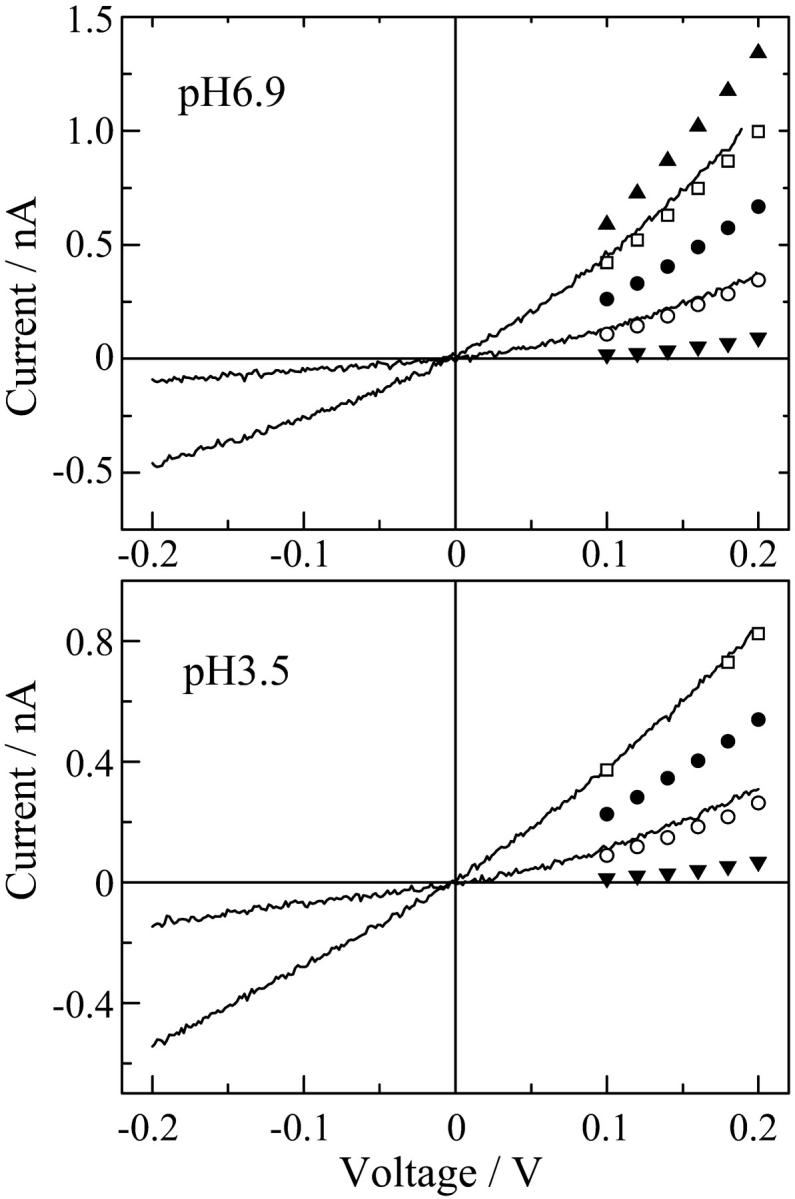
Current-voltage relations of single di-alm channels in 1 M KCl at pH 6.9 and pH 3.5. The data points obtained for alm channels are also indicated as: levels 1 (▾), 2 (○), 3 (•), 4 (□), and 5 (▴).
RESULTS
Microscopic channel current fluctuation
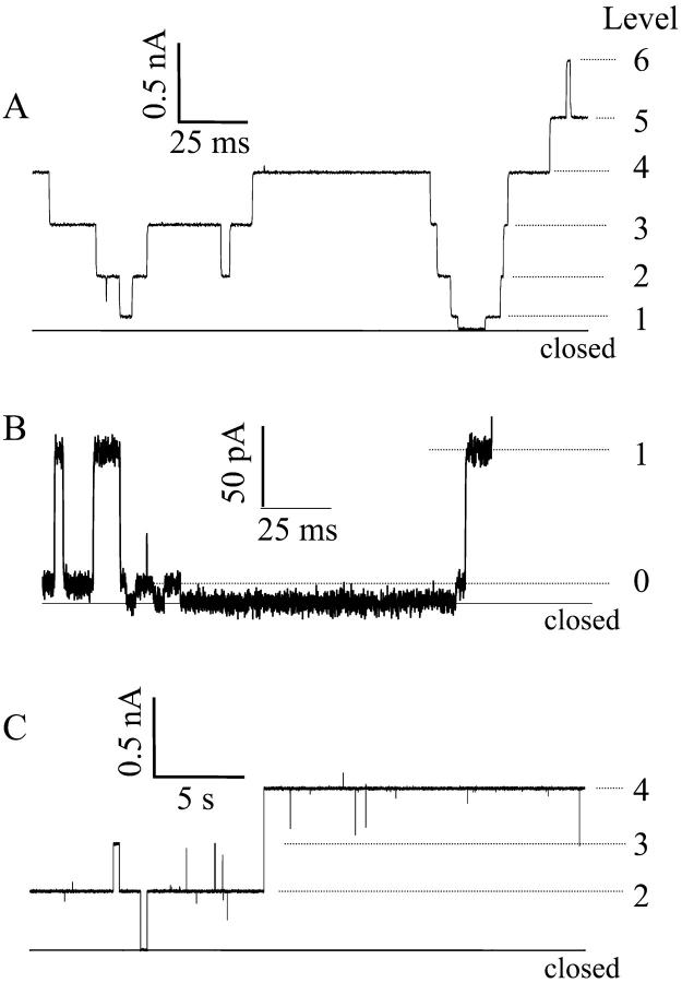
Fig. 4 shows typical current fluctuations induced by alamethicin Rf30 (alm) and its covalent dimer (di-alm) in 1 M KCl at pH6.9 and at 200 mV. Both the peptides exhibited multi-conductance behavior that was supposed to be due to transient changes in number of peptide helices in a single channel. The duration times of the open states were quite different between alm and di-alm; the mean lifetime of di-alm channels was ∼100 times longer than that of alm channels. The conductance levels are successively numbered from 0; level 0 corresponds to the lowest conductance state reported by Hanke and Boheim (1980). Note that our numbering for the conductance levels is different from that of Hanke and Boheim (1980), You et al. (1996), and Jaikaran et al. (1997) who used level 1 for the lowest conductance and level 0 for the closed state.
FIGURE 4.
Current fluctuations induced by alm (A and B) and di-alm (C) at 200 mV. Aqueous phase was 1 M KCl (pH 6.9). The current scale in B is expanded to distinguish the lowest conductance state (level 0) from the closed state.
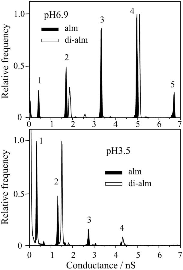
Fig. 5 shows the conductance histograms obtained from the current fluctuations measured at pH 3.5 and 6.9. For alm, there are found four (levels 1–4) and six (levels 1–6) discrete conductance levels at pH3.5 and 6.9, respectively, as reported previously (Asami et al., 2002). The lowest conductance state (level 0) seen in Fig. 4 B was not clearly distinguished from the closed state in the histograms. Each conductance levels were not a multiple of a unit conductance but correspond to single channels with different pore size. For di-alm, the relative probabilities of odd numbered levels (levels 1, 3, and 5) were extremely reduced, suggesting that even numbered levels correspond to channels assembled from even numbers of helices. The conductance values of level-2 and -4 channels were in fairly good agreement between alm and di-alm channels.
FIGURE 5.
Conductance histograms calculated from current fluctuations measured for alm and di-alm channels in 1 M KCl at pH 6.9 and pH 3.5. The applied voltage was 200 mV.
Single channel current-voltage characteristics
The intrinsic current-voltage (I-V) relationships of single di-alm channels in 1 M KCl at pH 3.5 and 6.9 were obtained by applying fast voltage ramps during the open states as described in Materials and Methods. The I-V curves of di-alm showed rectification, i.e., current at the positive voltage side was 2–3 times larger than that at the negative voltage side (Fig. 6). The I-V curves for di-alm were in good agreement with the data of alm channels that were measured within a limited voltage range. This suggests that the structures of di-alm and alm channels are similar to each others. Similar rectification has been reported for the single channels of C-terminally linked alamethicin dimers (Woolley et al., 1997).
Macroscopic current-voltage characteristics
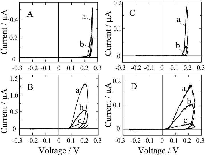
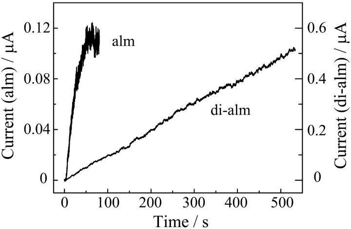
Fig. 7 shows macroscopic current-voltage (I-V) relations in 1 M KCl at pH 3.5 and pH7.0 when the cis-side of the membrane was doped to alm and di-alm. The sweep rate of applied voltage was varied from 1 mV/s to 100 mV/s. For both the peptides, ion channel currents appeared only at cis-positive voltages. The I-V curves were, however, different between the two peptides; marked hysteresis was observed for di-alm but not for alm. The hysteresis might be due to slow channel formation kinetics of di-alm. Indeed, the current induced by di-alm in response to a voltage jump was too slow to determine the time constant (Fig. 8).
FIGURE 7.
Macroscopic current-voltage characteristics for (A) alm at pH 3.5, (B) di-alm at pH 3.5, (C) alm at pH 7.0, and (D) di-alm at pH 7.0. Sweep rates of voltage (mV/s) were as follows. In A: (a) 10, (b) 100; in B: (a) 0.88, (b) 2.64, (c) 8.8; in C: (a) 2.4, (b) 24; in D: (a) 1, (b) 3, (c) 10. Aqueous phases contained 1 M KCl; alm and di-alm were added to the cis-side to a concentration of 5 nM and 2.5 nM, respectively.
FIGURE 8.
Time courses of macroscopic currents induced by alm and di-alm in response to voltage-jumps. At time 0, voltages were changed from 0 to 120 mV for alm and from 0 to 150 mV for di-alm. Aqueous phases were 1 M KCl (pH 7.0); alm and di-alm were added to the cis-side to a concentration of 5 nM and 2.5 nM, respectively.
DISCUSSION
Tethering of alamethicin at N-terminus by disulfide bond
The channels of N-terminally linked alamethicin dimer (di-alm) were formed at cis-positive voltages like alamethicin, suggesting that di-alm peptides also form parallel bundles by inserting the N-termini into a membrane. The fairly good agreement in the conductance of level-2 and -4 channels between alm and di-alm indicates that the tethering does not influence the normal channel formation, i.e., the linker has an appropriate length and flexibility for keeping the helices at the right positions in the channel.
The method of tethering used in this study is of merit in respect of synthesis with a solid-phase technique because an acm-protected mercaptopropionic acid is only condensed after completion of the assemblage of amino acids, i.e., a special linker is not required. This simple tethering would be applicable to other peptides forming helix-bundle type channels.
Number of alamethicin helices per channel
The multi-conductance behavior of alamethicin channels can be explained by transient changes in pore size because each conductance level was not a multiple of a unit conductance and has different nonlinearity in single-channel I-V characteristics (Asami et al., 2002). The transition between adjacent conductance states may be caused when a helix bundle uptakes or releases a helix. Hanke and Boheim (1980) presumed that the lowest conductance state (level 0) corresponds to the trimeric helix bundle because the pore diameter estimated from a space-filling model for the tetrameric helix bundle was too large to explain the lowest channel conductance. Thus, the number of helices (NH) per channel is related to the level number (NL) as NH = NL + 3. This relation was also supported from the single-channel recordings with alamethicin molecules bundled with cyclic templates, that were designed to emulate helix bundles (Matsubara et al., 1996). The relation, however, admits argument because the estimation by Hanke and Boheim (1980) is too simple to provide a correct channel conductance and the cyclic templates used by Matsubara et al. (1996) likely interfere with normal alignment of helices in a channel and influence the ion permeation. Recently, an alternative relation of NH = NL + 4 was suggested from the results with C-terminally linked alamethicin dimers (You et al., 1996; Jaikaran et al., 1997). The present results with the N-terminally linked alamethicin dimer supported the latter relation because the number of helices in level 0 channel would be more than three and an even number, i.e., level 0 channel corresponds to the tetrameric helix bundle.
Intrinsic rectification
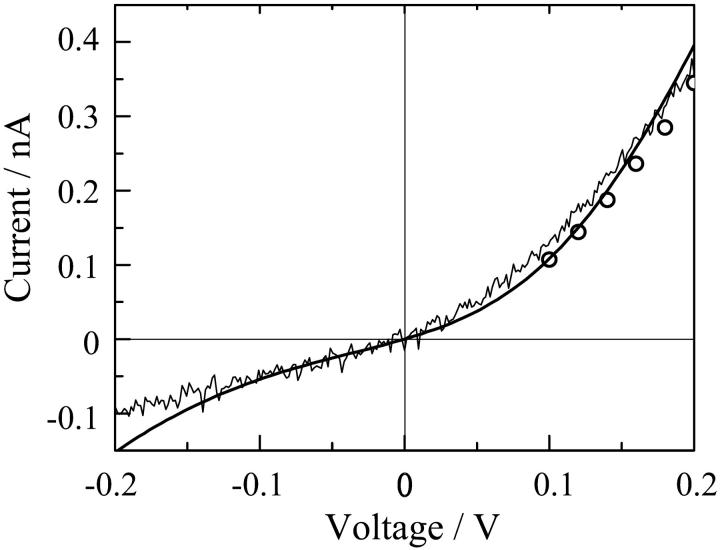
In a previous paper we simulated the I-V relations of single channels of alm, whose data were limited only at the cis-positive voltage side (Asami et al., 2002). The present results with di-alm provided the entire I-V curves over both positive and negative voltage sides, and showed rectification. Hence, it is interesting to examine if the previous theoretical calculation interprets the rectification. In the calculation, the I-V curve for the level-2 channel (a hexameric helix bundle) was obtained using generalized Nernst-Planck equation with the energy barriers for ion permeation that were calculated from the macroscopic pore model described in Materials and Methods. The theoretical curve well simulated the observed rectification (Fig. 9). Similar theoretical calculations also interpreted the rectification found for the channels of C-terminally linked alamethicin dimers (Woolley et al., 1997; Jaikaran et al., 1997). The rectification might be a common property of helix bundle type channels formed by peptides (Kienker et al., 1994; Kienker and Lear, 1995). The rectification is mainly attributed to macro dipoles of peptide helices forming a parallel bundle around a pore; the positive N-termini and the negative C-termini facilitate cation and anion flows at cis-positive voltages, but not at cis-negative voltages.
FIGURE 9.
Rectification of level-2 channels simulated by a macroscopic continuum model. The thin solid line indicates the observed I-V curve at pH 6.9 for di-alm and the open circles are the data points for alm. The thick smooth curve is the theoretical calculation using generalized Nernst-Planck equation, Eqs. 1–3 in a previous article (Asami et al., 2002), with the barrier parameters estimated on pages 224–226 of this reference. In the calculation, a hexameric helix bundle is assumed, the dipole moment per helix is 2.4 × 10⁻²⁸ cm and the total charge due to ionized Glu18 is 0.6e.
Macroscopic conductance-voltage relations
The macroscopic current-voltage (I-V) relations for di-alm and alm showed hysteresis loops, whose width depended on the sweep rate of voltage. The hysteresis loop for alm much narrowed at sufficiently low sweep rates, whereas the width of hysteresis for di-alm was little reduced even at 1 mV/s because of the very slow formation kinetics of di-alm channels. Since it is difficult to obtain the steady-state I-V curves for di-am, we will derive a formula that describes the macroscopic I-V relation to analyze the hysteresis loops.
The time course of the alamethicin-induced current in response to a voltage jump is well characterized by a first-order kinetic equation (Eisenberg et al., 1973; Boheim and Kolb, 1978). Since the number of pores N is proportional to the current, the time course of N can be represented by
 |
(1) |
where n is the rate of pore formation and m the rate of pore decay. This equation is rewritten as
 |
(2) |
where τ is the relaxation time (τ = 1/m), and Ns is the steady-state number of pores (Ns = n/m = nτ). The steady-state number of pores is empirically expressed by an exponential function of applied voltage V,
 |
(3) |
where Ve is the voltage change required to give an e-fold increase in number of pores, and N0 is the proportionality constant. The relaxation time τ also depends on applied voltage and is empirically given by
 |
(4) |
where Vτ is the voltage change required to give an e-fold increase in τ, and τ0 is the proportionality constant. The applied voltage linearly changes, and thus
 |
(5) |
where the voltage sweep rate Vr is positive in the increasing voltage limb and is negative in the decreasing voltage limb. Using Eqs. 2–5, we can obtain the following differential equation for the macroscopic conductance G,
 |
(6) |
where Gu is the mean unit conductance. The macroscopic conductance can be calculated by numerically integrating Eq. 6. If the relaxation time τ is long enough to assume that Ns (=nτ) ≫ N or N0 exp(V/Ve) ≫ N at high voltages, Eq. 6 is approximated in the increasing voltage limb as
 |
(7) |
Integrating Eq. 7 we obtain
 |
(8) |
or alternatively
 |
(9) |
Equation 9 predicts that ln G versus V plots show a linear relation with a slope of (1/Ve − 1/Vτ) in the increasing voltage limb.
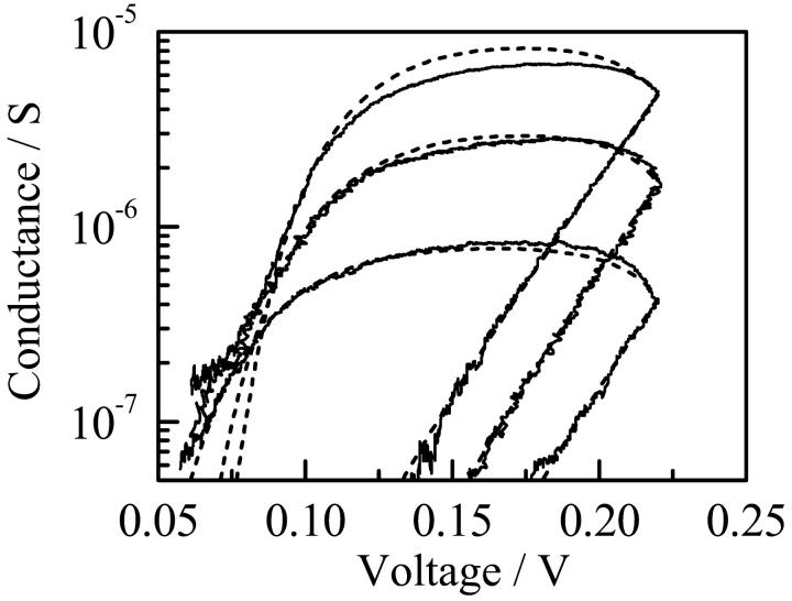
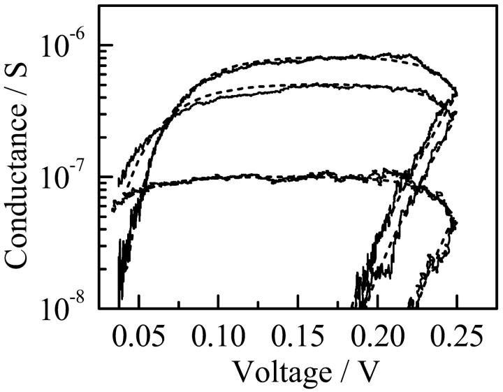
Figs. 10 and 11 show the log G versus V plots obtained from the I-V curves of di-alm shown in Fig. 7. In the increasing voltage limb, linear relations were obtained and the values of (1/Ve − 1/Vτ) estimated from the slopes were around 1/21 mV−1 independent of Vr as expected from Eq. 9. In the decreasing voltage limb, the conductance attained a maximum and decreased very slowly and then steeply. The log G versus V curves were well simulated using Eq. 6 and consistent values were obtained for the parameters Ve and Vτ, i.e., Ve =11 mV and Vτ = 23 mV.
FIGURE 10.
Plots of log G against V for di-alm at pH 3.5 shown in Fig.7. Sweep rates of voltage (mV/s) were: (top) 0.88, (middle) 2.64, and (bottom) 8.8. The dotted curves indicate best-fit curves calculated using Eq. 6.
FIGURE 11.
Plots of log G against V for di-alm at pH 7.0 shown in Fig.7. Sweep rates of voltage (mV/s) were: (top) 1, (middle) 3, and (bottom) 10. The dotted curves indicate best-fit curves calculated using Eq. 6.
The values of Ve estimated for di-alm were different from those obtained for alm, (6.0 mV at pH 3.5 and 5.4 mV at pH 7.0). The parameter Ve may be expressed by
 |
(10) |
where kB is the Boltzmann constant, T the temperature, e the elementary charge, α the effective gating charge per helix, and NH is the mean number of helices per channel. If we assume that the effective gating charge α is due to the orientation of a dipole from parallel to perpendicular to the membrane plane, the dipole moment μ per helix is
 |
(11) |
With rough estimates of NH from the conductance histograms shown in Fig. 5 and a membrane thickness of 3 nm, the values of α and μ were calculated in Table 1. The dipole moment estimated for alm was in good agreement with that experimentally determined (Schwarz and Savko, 1982), whereas the dipole moment of the corresponding helix in di-alm was lower than that of alm. Possible explanations for the difference in apparent dipole moment are that the N-terminal portion of di-alm is already inserted to some extent in the membrane before voltage activation and/or that two helix dipoles in di-alm interact each other to reduce the dipole moment.
TABLE 1.
Estimation of helix dipole moment and parameter α from macroscopic I-V measurements
| pH | Ve/mV | NH | α | μ/D | |
|---|---|---|---|---|---|
| alm | 3.5 | 6.0 | 7 | 0.61 | 88 |
| 8 | 0.53 | 76 | |||
| 7.0 | 5.4 | 8 | 0.59 | 85 | |
| 9 | 0.53 | 76 | |||
| di-alm | 3.5 | 11 | 6 | 0.39 | 56 |
| 7.0 | 11 | 8 | 0.29 | 42 |
The values of τ0 estimated for di-alm were ∼0.1 s at pH 3.5 and ∼1 s at pH 7.0. Thus, the values of τ become 600 s at pH 3.5 and 6000 s at pH 7.0 at 200 mV, which are calculated from Eq. 4 with Vτ = 23 mV. The relaxation times are much longer than those for alm. The relaxation time (τ) or the pore decay rate (1/τ) may be determined not only by the dissociation rate of peptide helices from the helix bundle but also by the lateral diffusion rate of peptide helices in the membrane. The tethering of alm could affect both the factors. The relaxation time of di-alm depended on pH, and similar pH dependence was observed with alm, as seen in Fig. 7. However, it is not well understood why the ionization of Glu at position 18 prolongs the relaxation time.
References
- Asami, K., T. Okazaki, Y. Nagai, and Y. Nagaoka. 2002. Modifications of alamethicin ion-channels by substitution of Glu7 for Gln7. Biophys. J. 83:219–228. [DOI] [PMC free article] [PubMed] [Google Scholar]
- Boheim, G., and H. A. Kolb. 1978. Analysis of the multi-pore system of alamethicin in a lipid membrane. I. Voltage-jump current-relaxation measurements. J. Membr. Biol. 38:99–150. [Google Scholar]
- Cafiso, D. S. 1994. Alamethicin: a peptide model for voltage gating and protein-membrane interactions. Annu. Rev. Biophys. Biomol. Sruct. 23:141–165. [DOI] [PubMed] [Google Scholar]
- Duclohier, H., K. Kociolek, M. Stasiak, M. T. Leplawy, and G. R. Marshall. 1999. C-terminally shortened alamethicin on templates: influence of the linkers on conductances. Biochim. Biophys. Acta. 1420:14–22. [DOI] [PubMed] [Google Scholar]
- Duclohier, H., G. Mole, and G. Spach. 1989. The influence of the trichozianin C-terminal residues on the ion channel conductance in lipid bilayers. Biochim. Biophys. Acta. 987:133–136. [DOI] [PubMed] [Google Scholar]
- Duclohier, H., and H. Wrólewski. 2001. Voltage-dependent pore formation and antimicrobial activity by alamethicin and analogues. J. Membr. Biol. 184:1–12. [DOI] [PubMed] [Google Scholar]
- Eisenberg, M., J. E. Hall, and C. A. Mead. 1973. The nature of the voltage-dependent conductance induced by alamethicin in black lipid membranes. J. Membr. Biol. 14:143–176. [DOI] [PubMed] [Google Scholar]
- Fox, R. O., Jr., and F. M. Richards. 1982. A voltage-gated ion channel model inferred from the crystal structure of alamethicin at 1.5-Å resolution. Nature. 300:325–330. [DOI] [PubMed] [Google Scholar]
- Futaki, S., M. Fukuda, M. Omote, K. Yamauchi, T. Yagami, M. Niwa, and Y. Sugiura. 2001. Alamethicin-leucine zipper hybrid peptide: a prototype for the design of artificial receptors and ion channels. J. Am. Chem. Soc. 123:12127–12134. [DOI] [PubMed] [Google Scholar]
- Jaikaran, D. C. J., P. C. Biggin, H. Wenschuh, M. S. P. Sansom, and G. A. Woolley. 1997. Structure-function relationships in helix-bundle channels probed via total chemical synthesis of alamethicin dimers: Effects of a Gln7 to Asn Mutation. Biochemistry. 36:13873–13881. [DOI] [PubMed] [Google Scholar]
- Hanke, W., and G. Boheim. 1980. The lowest conductance state of the alamethicin pore. Biochim. Biophys. Acta. 596:456–462. [DOI] [PubMed] [Google Scholar]
- Hall, J. E., I. Vodyanoy, T. M. Balasubramanian, and G. R. Marshall. 1984. Alamethicin: A rich model for channel behavior. Biophys. J. 45:233–247. [DOI] [PMC free article] [PubMed] [Google Scholar]
- Kienker, P. K., W. G. DeGrado, and J. D. Lear. 1994. A Helical-dipole model describes the single-channel current rectification of an uncharged peptide ion channel. Proc. Natl. Acad. Sci. USA. 91:4859–4863. [DOI] [PMC free article] [PubMed] [Google Scholar]
- Kienker, P. K., and J. D. Lear. 1995. Charge selectivity of the designed uncharged peptide ion channel Ac-(LSSLLSL)3-CONH2. Biophys. J. 68:1347–1358. [DOI] [PMC free article] [PubMed] [Google Scholar]
- Koide, N., K. Asami, and T. Fujita. 1997. Ion channels of hypelcins, antibiotic peptides, formed in planar bilayer lipid membranes. Biochim. Biophys. Acta. 1326:47–53. [DOI] [PubMed] [Google Scholar]
- Latorre, R., and O. Alvarez. 1981. Voltage-dependent channels in planar lipid bilayer membranes. Physiol. Rev. 61:77–150. [DOI] [PubMed] [Google Scholar]
- Marbach, P., and J. Rudinger. 1974. Synthesis of [2-p-Fluorophenylalanine]oxytocin and its desamino analogue using the S-acetamidomethyl protecting group. Helvetica Chimica Acta. 57:403–414. [DOI] [PubMed] [Google Scholar]
- Matsubara, A., K. Asami, A. Akagi, and N. Nishino. 1996. Ion channels of cyclic template-assembled alamethicins that emulate the pore structure predicted by barrel-stave model. J. Chem. Soc. Chem. Commun. 2069–2070.
- Mueller, P., and D. O. Rudin. 1968. Action potentials induced in bimolecular lipid membranes. Nature. 217:713–719. [DOI] [PubMed] [Google Scholar]
- Nagaoka, Y., A. Iida, S. Hatanaka, K. Tomioka, K. Asami, and T. Fujita. 1996a. Ion channel properties of disulfide-linked dimer derivatives of peptaibol, trichosporin-B-Via. Pept. Chem. 34:189–192. [Google Scholar]
- Nagaoka, Y., A. Iida, T. Kambara, K. Asami, E. Tachikawa, and T. Fujita. 1996b. Role of proline residue in the channel-forming and catecholamine-releasing activities of the peptaibol, trichosporin-B-Via. Biochim. Biophys. Acta. 1283:31–36. [DOI] [PubMed] [Google Scholar]
- Sansom, M. S. P. 1991. The biophysics of peptide models of ion channels. Prog. Biophys. Mol. Biol. 55:139–235. [DOI] [PubMed] [Google Scholar]
- Schwarz, G., and P. Savko. 1982. Structural and dipolar properties of the voltage-dependent pore former alamethicin in octanol/dioxane. Biophys. J. 39:211–219. [DOI] [PMC free article] [PubMed] [Google Scholar]
- Vodyanoy, I., J. E. Hall, and T. M. Balasubramanian. 1983. Alamethicin-induced current-voltage curve asymmetry in lipid bilayers. Biophys. J. 42:71–82. [DOI] [PMC free article] [PubMed] [Google Scholar]
- Wenschuh, H., M. Beyermann, H. Haber, J. K. Seydel, E. Krause, M. Bienert, L. A. Carpino, A. El-Faham, and F. Albericio. 1995. Stepwise automated solid phase synthesis of naturally occurring peptaibols using FMOC Amino Acid Fluorides. J. Org. Chem. 60:405–410. [Google Scholar]
- Woolley, G. A., P. C. Biggin, A. Schultz, L. Lien, D. C. J. Jaikaran, J. Breed, K. Crowhurst, and M. S. P. Sansom. 1997. Intrinsic rectification of ion flux in alamethicin channels: Studies with an alamethicin dimer. Biophys. J. 73:770–778. [DOI] [PMC free article] [PubMed] [Google Scholar]
- Woolley, G. A., and B. A. Wallace. 1992. Model ion channels: gramicidin and alamethicin. J. Membr. Biol. 129:109–136. [DOI] [PubMed] [Google Scholar]
- You, S., S. Peng, L. Lien, J. Breed, M. S. P. Sansom, and G. A. Woolley. 1996. Engineering stabilized ion channels: covalent dimers of alamethicin. Biochemistry. 35:6225–6232. [DOI] [PubMed] [Google Scholar]


