

Abstract
Intermediate filaments (IFs) impart mechanical integrity to cells, yet IF mechanics are poorly understood. It is assumed that IFs in cells are as stiff as hard α-keratin, F-actin, and microtubules, but the high bending flexibility of IFs and the low stiffness of soft α-keratins suggest that hydrated IFs may be quite soft. To test this hypothesis, we measured the tensile mechanics of the keratin-like threads from hagfish slime, which are an ideal model for exploring the mechanics of IF bundles and IFs because they consist of tightly packed and aligned IFs. Tensile tests suggest that hydrated IF bundles possess low initial stiffness (Ei = 6.4 MPa) and remarkable elasticity (up to strains of 0.34), which we attribute to soft elastomeric IF protein terminal domains in series with stiffer coiled coils. The high tensile strength (180 MPa) and toughness (130 MJ/m3) of IF bundles support the notion that IFs lend mechanical integrity to cells. Their long-range elasticity suggests that IFs may also allow cells to recover from large deformations. X-ray diffraction and congo-red staining indicate that post-yield deformation leads to an irreversible α→β conformational transition in IFs, which leads to plastic deformation, and may be used by cells as a mechanosensory cue.
INTRODUCTION
Since the advent of the electron microscope, cell biologists have known that a complex network of filaments known as the cytoskeleton permeates the cytoplasm of eukaryotic cells. Most animal cells possess three types of cytoskeletal filaments: filamentous actin (F-actin), microtubules, and intermediate filaments (IFs). IFs are ∼10 nm in diameter, and in living cells are typically clustered around the nucleus, with filaments radiating peripherally to connect with desmosomes and hemidesmosomes (Alberts et al., 1994).
IF knockout studies have provided definitive evidence that IFs impart mechanical integrity to cells (Fuchs and Cleveland, 1998; Magin et al., 2000), but exactly how they do this is unknown. The mechanical properties of α-keratins such as wool have been extensively characterized (Hearle, 2000) and because IFs are the major component in these materials, it is assumed that the properties of IFs in cells are similar. This assumption has been accepted as reasonable because α-keratins have a stiffness (E ≈ 2 GPa) that is similar to the other two cytoskeletal filaments, F-actin (E = 2.5 GPa) (Gittes et al., 1993; Kojima et al., 1994), and microtubules (E = 1 GPa) (Felgner et al., 1996; Gittes et al., 1993; Kurachi et al., 1995). In addition, IF protein dimers possess prominent coiled coil motifs, which are also known to have a stiffness of ∼2 GPa (Howard, 2001).
IFs are flexible in bending
Although the above evidence suggests that IFs are as stiff as α-keratins, IFs exhibit a high flexibility in bending that is difficult to reconcile with this assumption, because bending is essentially a special case of tension and compression. The evidence for the great flexibility of IFs comes from light scattering experiments (Hohenadl et al., 1999), and TEM imaging (Howard, 2001). These kinds of experiments suggest that IFs exhibit persistence lengths (Lp) on the order of 1 μm. Lp is a useful measure of a filament's flexibility, and is roughly the minimum length at which the filament ends become uncorrelated due to Brownian motion (Gittes et al., 1993). Lp can be calculated for a solid rod from the following parameters:
 |
(1) |
where E is the Young's modulus or stiffness, I is the second moment of area (proportional to the radius to the fourth power for a cylinder), k is Boltzmann's constant, and T is temperature. To put the low Lp of IFs in perspective, the Lp for microtubules and F-actin are ∼5000 μm and 18 μm, respectively (Felgner et al., 1996; Gittes et al., 1993; Kojima et al., 1994; Kurachi et al., 1995). Note that the IF Lp is considerably smaller than F-actin's despite the fact that IFs have a larger radius. If IFs truly have a stiffness of 2 GPa as is assumed, Eq. 1 predicts that they should have an Lp of ∼230 μm, or more than two orders of magnitude higher than the Lp obtained via light scattering or TEM. This apparent paradox (i.e., IFs are stiff in tension but flexible in bending) has been explained by invoking a mechanism whereby the subfilaments within IFs can slide freely past one another during bending, much like the filaments within a rope (Bray, 2001; Hohenadl et al., 1999; Howard, 2001). We hypothesized that IFs behave as solid rods, with their great flexibility due to an inherently low tensile stiffness. Specifically, this hypothesis predicts that IFs have a tensile stiffness of ∼8 MPa rather than the 2 GPa assumed in the literature. Although a stiffness of 8 MPa is dramatically lower than the stiffness of hard α-keratins, it is remarkably similar to the modulus of hydrated soft α-keratins such as stratum corneum (3–4 MPa), especially if one considers that the IFs in soft keratins are not axially aligned.
Ideally the tensile stiffness of individual IFs could be measured using techniques such as atomic force microscopy, although this has yet to be accomplished. Up to this point, the state of the art for studying the mechanical properties of IFs has been to work with macroscopic samples of IF suspensions (protein concentration = 1–2 mg/mL) that set into entropic gels (Bousquet et al., 2001; Hofmann and Franke, 1997; Janmey et al., 1991; Ma et al., 1999, 2001). Although this approach has been useful for studying the properties of entangled IF networks, it does not allow one to infer the properties of IFs loaded directly in tension, given that gel mechanics depend mostly on filament concentration and the number and strength of cross-links, and less on the mechanical properties of the filaments themselves (Ma et al., 1999). The task is akin to inferring the properties of collagen fibrils (tensile modulus = 1.2 GPa) (Pollock and Shadwick, 1994) from the properties of soft gelatin gels.
The next best thing to testing individual IFs would be to work with a bundle of pure, highly aligned IFs, just as tendon provides a useful model for measuring the properties of collagen fibrils. This kind of approach is especially useful given the fact that many IFs form bundles in vivo (Ma et al., 2001). Fortuitously, hagfishes (class Agnatha, order Cyclostomata) produce a defensive mucus that is reinforced with keratin-like threads (Downing et al., 1981b; Koch et al., 1995) that are analogous to IF tendons, and have been hailed as an ideal model for exploring many aspects of IF structure and function (Downing et al., 1984). These threads (hereafter referred to as “hagfish threads”) are manufactured within the cytoplasm of specialized cells in hagfish slime glands. These “gland thread cells” are ejected via the holocrine mode from the slime glands, and lose their plasma membrane in the process (Fig. 1 A), releasing a single, continous IF bundle that is 1–3 μm in diameter (Downing et al., 1981b) and ∼10–20 cm long when completely unraveled (Downing et al., 1981b; Fernholm, 1981).
FIGURE 1.

(A) SEM of a mature gland thread cell (without its plasma membrane) from Eptatretus stoutii. These unique cells manufacture a single, continuous bundle of keratin-like IFs that eventually occupies the vast majority of the cell volume. Scale bar = 25 μm. (B) SDS-PAGE of isolated hagfish threads demonstrates that the threads are composed of 67 kDa IF proteins, with very little contamination from other proteins (D. Fudge and J. Gosline, unpublished data).
Extensive studies by Downing et al. (1984) and Terakado et al. (1975) of the ultrastructure of developing threads using TEM demonstrate the utility of this experimental model. In immature thread cells, transverse and longitudinal sections of the thread demonstrate that the IFs within the thread exhibit strong alignment parallel to the thread axis. As the cells mature, the IFs within the thread become more numerous and densely packed, such that it becomes difficult to resolve individual IFs, even with high resolution TEM. From these images, and our own measurements of hagfish thread swelling (D. Fudge and J. Gosline, unpublished data), we estimate that the protein concentration in hydrated hagfish threads approaches 1000 mg/mL. Hagfish threads, therefore, consist of an almost pure (Fig. 1 B), solid bundle of keratinlike IFs that exhibit near-perfect axial alignment.
Studies by Koch et al. (1994, 1995) demonstrate that hagfish thread IFs are composed of two proteins (α and γ) that qualify for inclusion in the IF family of proteins. While α and γ do not fit neatly into the keratin family of IF proteins, they have been classified as “keratin-like,” and they share nearly all of the hallmarks of IF proteins such as IF domain and subdomain structure, heptad repeats, linker sequences, and even the “stutter” in region II B. Perhaps most importantly, α and γ assemble in vitro into 10-nm filaments (Koch et al., 1995). For these reasons, hagfish thread IFs are a convenient experimental model for exploring the tensile mechanics of IFs.
The keratin α↔β transition
One of the major findings that came out of efforts to understand the molecular basis of wool mechanics is a phenomenon known as the alpha-to-beta transition (or α↔β transition). From x-ray diffraction data it was shown that fibrous proteins within wool exist primarily as α-helices aligned with the fiber axis (Fraser et al., 1972). X-ray data also show that stretching the fibers in steam results in a loss of α-helical structure and the creation of a new, extended β-pleated sheet conformation (Bendit, 1960). We now know that the fibrous proteins responsible for these x-ray diffraction patterns in wool are keratin IF proteins. Cell biologists have never investigated the possibility that cytoplasmic IFs also undergo an α↔β transition. Using hagfish threads as an IF model, we hypothesized that IFs within cells also undergo an α↔β transition as they do in keratins.
Here we provide evidence from experiments with hagfish threads that hydrated IFs are not only soft in bending, but also in tension, with an initial stiffness of 7.0 MPa. In addition we demonstrate that hydrated IFs undergo an irreversible α→β transition at large strains. The mechanical properties we present here for hagfish threads have important implications for the tensile properties of IF bundles and IFs in cells. Namely, our data suggest that IFs may function as soft elastic elements that impart long-range elasticity to cells, and that the irreversible α→β transition, which toughens and strengthens the hagfish threads, may dramatically reinforce cytoskeletal IFs in extreme cellular deformations. We also propose that strain-induced β-sheets in IFs may serve as an important mechanosensory cue in cells. We end the Discussion with an analysis of the implications of our data for current theories of cytoskeletal mechanics.
MATERIALS AND METHODS
Experimental animals
Pacific hagfish (Eptatretus stoutii) were obtained with assistance of staff at the Bamfield Marine Station in Bamfield, British Columbia. Traps were baited with herring and set in Barkley Sound on the bottom at a depth of ∼100 m and left overnight. Hagfish were transported back to the University of British Columbia where they were held in a 200-L aquarium of chilled seawater (34‰, 9°C) in accordance with the regulations of the UBC Committee on Animal Care (protocol A2-0003).
Slime collection
Slime exudate was collected using techniques modified from Ferry (1941) and Downing et al. (1981a). Hagfish were anesthetized in a 5-L bucket of buffered anesthetic (250 mg/L MS-222, 500 mg/L sodium bicarbonate) in seawater until they became unresponsive to touch. They were then placed on a dissection tray nested in ice, and a small portion of their skin was rinsed with distilled water and blotted dry. Slime exudate was expressed from slime glands in the rinsed area using mild electrical stimulation (8V, 80 Hz), which caused contraction of the skeletal muscle that encapsulates each gland. Exudate was collected with a small spatula and transferred to a high osmolarity citrate buffer (0.9 M sodium citrate, 0.1 M PIPES, pH 6.7) modified from Downing et al. (1981a). To safeguard against proteolysis, 1 mL of protease inhibitor cocktail (Sigma Aldrich product number P2714) was added to every 100 mL of stabilization buffer.
Micromechanical apparatus
Tensile properties of hagfish threads were measured using a modification of a glass microbeam force transducer apparatus described in Gosline et al. (1994). The technique is based on the premise that extremely small tensile forces can be measured by attaching a test sample to a fine glass microbeam and monitoring the bending of the beam under a microscope as the sample is deformed. Deflections of the beam can be converted to force values using an equation derived from beam theory:
 |
(2) |
where F is the force, d is the deflection of the beam, E is the Young's modulus of glass, I is the second moment of area of the beam, and l is the length of the beam. The linear relationship between force and deflection holds for beam deflections up to ∼10% of the length, and for this reason glass microbeams were chosen so that the maximum deflection during a test was typically only 1% of the length (200 μm deflection for a 20-mm beam). The diameters of the glass beams used as transducers were often not perfectly constant along their length, but rather were slightly tapered. For a uniformly tapered cylinder with radii r1 and r2 (where r1 is the radius at the point where the beam is fixed, and r2 is the radius where the sample is attached), I = π(r13 r2)/4 (Gosline et al., 1994).
The Young's modulus of the microbeams was not measured directly, but rather using larger glass rods from which the microbeams were pulled. Glass rods of diameter 3 mm and length 50 cm were mounted horizontally in the jaws of a vise, masses hung from their ends, and the deflection measured using a mounted ruler. From the glass rod radius, length, and deflection under a given load, the elastic modulus was calculated from beam theory (Eq. 2) to be 5.72 ± 0.06 × 10¹⁰ N/m2.
The length of the glass microbeams (i.e., the distance from its base to the point of attachment of the thread) was measured after each test to the nearest 0.02 mm using calipers. Microbeam diameter was measured to the nearest μm at the base and point of thread attachment eight times using a 15× filar micrometer eyepiece and 10× objective on a Wild compound microscope.
Individual stabilized thread skeins from gland thread cells were transferred to a seawater-filled glass-bottomed micromechanical chamber (Fig. 2) using a sharpened toothpick. The skeins were allowed to unravel, and a 10-mm segment was mounted at one end to the glass microbeam (diameter = 50–125 μm (depending on the nature of the mechanical test), length ≈ 15 mm), and at the other to a sliding glass platform that could be moved in either direction by turning a micrometer knob. To secure threads to the microbeam, they were first wrapped around it ∼10 times, and then fixed in place using a small amount of Cenco Softseal TackiWax (Central Scientific Company, Chicago, IL) applied with a fine needle. At the other end, threads were embedded in a 1-mm slab of TackiWax mounted on the sliding glass platform.
FIGURE 2.

Micromechanical testing apparatus used to measure the tensile properties of isolated lengths of hagfish threads in seawater. VDA = video dimension analyzer.
Before testing, the moveable platform was adjusted until the thread segment was just taut. Observation of the mounted thread segments under a dissecting scope confirmed that bending of the glass rod only occurred when the thread was straight and taut. Threads were extended (strain rate = 0.017 s−1 ± 0.0006 (SE)) by coupling the micrometer knob to a 72-rpm motor via a flexible belt. Force was measured by monitoring the bending of the glass microbeam with a video camera mounted on a Wild M-21 light microscope using a low power (4×) objective. Deflection of the microbeam was quantified using a video dimension analyzer (VDA model 303, Instrumentation for Physiology and Medicine, San Diego, CA), and voltage output from the VDA was collected at 20 Hz using a National Instruments (Austin, TX) DaqPad 4060E input/output board and LabView v. 5 data collection software.
Strain (change in length/resting length) was calculated from the time field using a calibration of the translation speed of the micrometer/motor setup and the resting length of the mounted thread, which was measured with calipers. The strain value inferred from the time field was corrected for the deflection of the microbeam by subtracting the deflection from the distance traveled by the traveler arm. The voltage output of the VDA was calibrated against a Bausch and Lomb calibration slide with 0.1 mm increments. The slope of the voltage versus length calibration curve was 10.68 V/mm, with an r2 value of 0.9998.
Thread diameter
Thread diameter was obtained for stress calculations in one of two ways depending on the nature of the tensile test. For tests in which the thread returned to its original dimensions after the test (see Fig. 5 C), the test thread was used for the diameter measurement. At the conclusion of a test, threads were returned to their original length and mounted under a coverglass in seawater while still attached to both the glass microbeam and the sliding glass platform. For tests in which thread diameter may have been altered by the test, an adjacent piece of hagfish thread was snipped off the test piece before testing and stuck to the glass of the chamber using stopcock grease so that its diameter could be measured after the mechanical test was complete. Diameter was measured under high power (100× interference contrast, oil immersion objective) on a Leitz orthoplan polarizing microscope (Ernst Leitz Canada, Midland, Ontario) using a 15× Filar-micrometer eyepiece. For each sample, diameter was measured six times with typical SD values of 0.15 μm for each thread.
FIGURE 5.

Recovery behavior of hagfish threads in seawater. (A) Typical load cycle in region I, showing completely reversible deformation. (B) Typical load cycle into region II, showing that deformation past the yield point is mostly plastic. (C) Results from trials in which threads were extended to a given strain, held, and allowed to recover. Note that deformation is elastic up to a strain of 0.35, and plastic thereafter.
Degree of uncertainty in force, stress, and modulus measurements
Four variables were used to calculate force generation by the hagfish threads during tensile tests: namely the deflection of the microbeam (measured using the VDA), the Young's modulus of glass, the radius of the microbeam (used to calculate its second moment of area (I), and measured using a filar eyepiece micrometer), and the length of the microbeam (measured using vernier calipers). From the uncertainty of each of these measurements, and the exponents to which each variable is raised, it is possible to calculate a combined uncertainty of the force measurements from the following equation (Beckwith et al., 1993):
 |
(3) |
where uF, ul, ur, uE, and ud are the uncertainties of the force, beam length, beam radius, Young's modulus of glass, and beam deflection, respectively. The values for each of the four uncertainty terms on the right side of the equation expressed as percentages are ∼2%. We should note that the uncertainty of the glass microbeam radius was higher for the trials performed with the more sensitive beam due to its smaller size. These combine to give an error estimate for the force measurements of ∼10%. The same strategy can be applied to calculate the uncertainty in stress measurements, which were calculated from the force measurements and the radius of the threads used for each test. The uncertainty in the thread radius measurements was ∼15%, so using an equation analogous to Eq. 3 yields an estimate of the stress uncertainty of ∼32%. Stiffness was calculated from stress and strain measurements, and the error for the latter was ∼2%, so the combined error for thread stiffness measurements is still ∼32%.
IF bending strain and persistence length
Lp was calculated using Eq. 1 assuming an IF diameter of 10 nm and a packing efficiency of IFs within hagfish threads of 90.7% (hexagonal arrangement of cylinders), with the remaining space occupied by nonload-bearing water. Lp was calculated for a temperature of 20°C. Because the hagfish thread stress-strain curve is not linear, it was necessary to gauge the range of strains that are relevant to IF bending. We accomplished this by measuring the radius of curvature from several TEM images of IFs in the literature (Hofmann et al., 1991; Porter et al., 1998; Wang et al., 2000a,b) and estimating maximum strain from the circumference at the outer edge (i.e., the strained length), and the circumference at the neutral axis (i.e., the unstrained length) using the following equation:
 |
(4) |
where ro is the radius of curvature at the outer edge, and rn is the radius of curvature at the neutral axis. From this analysis, we determined that the IF bends usually have a radius of curvature no smaller than 0.1 μm, which corresponds to a maximum strain of ∼0.05 in a filament with a diameter of 10 nm. Because most bends had a radius of curvature considerably greater than 0.1 μm, and because 0.05 represents the strain experienced by only a small portion of a bending IF (material closer to the neutral axis experiences less strain), we chose to estimate the Young's modulus over the first 0.02 strain units.
The effect of subfilament sliding on Lp was estimated using a modification of Eq. 1 in which the second moment of area was calculated as the sum of the second moments of all subfilaments, and assuming a constant total filament cross-sectional area (A = π (5 nm)2).
 |
(5) |
where n is the number of subfilaments.
Recovery trials
For recovery trials in which the ability of hagfish threads to return to their original length was quantified, threads were mounted in the micromechanical testing chamber as described above, with one modification. Because force data were not required for these tests, threads were mounted at both ends in a slab of TackiWax. Recovery as a function of strain was quantified by deforming threads to a set strain, holding at that strain for one minute and then slacking them off for 10 minutes before the new resting length was measured.
Congo-red staining
To test for the presence of β-sheets in stretched hagfish threads, threads were stained with congo red (CR). CR is a dye used for the detection of amyloid fibers that creates an apple-green birefringence when it interacts with amyloid β-sheets (Puchtler et al., 1985). Threads were strained in seawater as described above, slackened and allowed to recover for one hour, after which the seawater was removed, and the threads dried onto the glass of the chamber. Threads were rinsed with distilled water (×2) and dried before 2 h of staining in a 1% CR in 10% ethanol solution (Knight et al., 2000). Threads were de-stained with distilled water, dried, and mounted in immersion oil for visualization under the polarizing microscope.
X-ray diffraction
X-ray diffraction of hagfish threads as a function of strain (ɛ = 0, 0.6, 1.0) was performed at the microfocus beamline (ID13) of the European Synchrotron Radiation Facility in Grenoble, France (Riekel, 2000). Preliminary attempts with single threads using a protein crystallography microdiffractometer with a 5-μm beam (Cusack et al., 1998) revealed that the signal to noise ratio for single hagfish threads was prohibitively low, necessitating the use of thread bundles.
Thread bundles were prepared by the successive mounting of individual threads into TackiWax, resulting in a bundle of 50–75 hagfish threads in distilled water. The bundles were strained (or not in the case of the unstrained treatment) and the water in the chamber gradually removed so that the bundle dried down onto a 3-mm copper TEM grid from which the central 200 μm was excised, leaving only the outer rim. Care was taken to avoid unwanted straining of the bundles as they were isolated onto the copper grids. By our estimates, pre-strain from these procedures could have been as high as 0.10, but was more likely below 0.05.
Bundles were secured to the rim with a small bead of 5-min epoxy. The TEM grids were mounted on a glass tip attached to a Huber goniometer head and optically prealigned. A motorized x/y/z gantry allowed precise placement of the sample in the beam. The thread bundle experiments were performed using the scanning setup at the ID13 beamline with glass capillary optics and a 3-μm beam (λ = 0.976 Å). No apparent radiation damage was observed at room temperature for average exposure times of 3 min per bundle. Diffraction patterns were collected using a slow-scan MAR CCD detector.
RESULTS
Hagfish threads possess low initial stiffness
Tensile tests of hagfish threads using the most sensitive microbeam force transducer (50 μm diameter) revealed that hagfish threads possess a low initial stiffness of only 6.4 ± 0.9 MPa (Fig. 3, Table 1). If one assumes ideal hexagonal packing of IFs in the hagfish threads, these initial stiffness values translates into an IF Ei of 7.0 ± 1.0 MPa. Calculation of the persistence length based on this stiffness (Eq. 1) yields an Lp of 0.85 ± 0.12 μm for the IFs that make up the hagfish threads.
FIGURE 3.

Stress-strain curves for the eight hagfish threads used to measure the initial tensile stiffness (Ei). The heavy dark line is the average stiffness calculated from these data (Ei = 6.4 ± 0.9 MPa).
TABLE 1.
Mechanical properties of hagfish threads tested in seawater
| Ei(MPa) | Yield ɛ(ΔL/Lo) | Yield σ (MPa) | Extensibility (ΔL/Lo) | Strength (MPa) | Toughness (MJ/m3) | |
|---|---|---|---|---|---|---|
| 6.4 ± 0.9 | 0.34 ± 0.01 | 3.2 ± 0.4 | 2.2 ± 0.2 | 180 ± 20 | 130 ± 20 | |
| (8) | (12) | (12) | (14) | (9) | (9) | |
| SD | 2.5 | 0.03 | 1.4 | 0.8 | 60 | 60 |
Values are mean ± SE. Sample sizes are in parentheses. SD = standard deviation.
The hagfish thread stress-strain curve is complex
Ultimate tests of hagfish threads in water revealed complex mechanical behavior, with the low initial stiffness described above giving way to extreme strain hardening (Fig. 4 A). Fig. 4 B is a plot of the instantaneous stiffness of a typical hagfish thread as a function of strain. From this analysis, at least four distinct mechanical regions can be identified. Region I is a low-stiffness initial region that terminates with a yield point at a strain of ɛ ≈ 0.34. Region II is a low stiffness plateau that terminates at a strain of ɛ ≈ 0.7. In region III, stiffness rises dramatically until a strain of ɛ ≈ 1.6. Region IV begins with a gradual drop in stiffness at a strain of ɛ ≈ 1.6 and continues to drop until a strain of ɛ ≈ 2.0, after which it remains approximately constant until failure.
FIGURE 4.

Ultimate tensile behavior of hagfish threads in seawater. (A) Typical stress-strain curve for hagfish threads strained to failure. Inset at top left is detail of stress-strain curve within box at lower left. (B) Plot of the instantaneous stiffness as a function of strain. Roman numerals denote the four distinct regions of the stress-strain curve.
Deformation is elastic in region I and plastic in regions II–IV
Load cycles revealed that deformation in region I is elastic, i.e., the threads returned to their original length (Fig. 5 A). The average resilience for nine load cycles performed in region I was 62 ± 3% (SE). The ability of the threads to return to their original length indicates that frictional sliding of IFs within the threads does not occur, at least in region I. In contrast, deformations in regions II–IV were not elastic, exhibiting a considerable plastic component (Fig. 5). While plastic deformation could indicate frictional sliding of IFs within the threads, congo-red and x-ray diffraction data clearly demonstrate that the onset of plastic deformation instead corresponds to the opening up of IF protein α-helices and the formation of β-sheets.
Hagfish threads are strong and tough
Ultimate tests revealed that hagfish threads in seawater fail at a stress of 180 ± 20 MPa and a strain of 2.2 ± 0.2 (Fig. 4, Table 1). Their modest failure stress combined with their high ultimate strain combine to give them an extremely high energy to break (or toughness) of 130 ± 20 MJ/m3 (Table 1).
Error analysis
The stress-strain data in Fig. 3 exhibit considerable variability. Comparing this variability with the uncertainty estimates provided in the Materials and Methods reveals that most of this variability can be accounted for by measurement error. The standard deviations for each mechanical measurement are provided in Table 1. Note that the variability (expressed as SD/mean·100%) was greatest for the values that depended upon measurement of the thread diameter (Ei SD = 40%, yield σ SD = 43%, strength SD = 33%, and toughness SD = 46%). The yield ɛ, which does not depend upon thread diameter showed far less variability (10%), suggesting that uncertainty in thread diameter is the dominant source of error. Furthermore, the magnitude of the variability in Table 1 is close to the values predicted by our error analysis in the Materials and Methods section. This suggests that most of the variability in our data can be explained by inherent uncertainty in the measurement process, and need not be attributed to sample variation. In spite of the considerable variability, the data are more than capable of distinguishing between the two hypotheses laid out in the Introduction (Ei = 8 MPa vs. Ei = 2 GPa), and provide a valuable first approximation of IF tensile properties.
Hagfish threads undergo an α→β transition at strains greater than 0.3–0.4
Threads strained into region I and then stained with congo red exhibited no CR birefringence, which indicated a lack of β-sheet structure in these threads. In fact CR had a chaeotropic effect on these threads, causing them to swell to several times their original diameter. Hagfish threads strained into region II displayed distinctive apple green CR-birefringence (Fig. 6 C) and did not appear swollen. Interestingly, the degree of CR metachromasia varied strongly with the strain. In region II, threads ranged from orange-yellow to green (Fig. 6, B and C), whereas in region III, threads appeared blue to blue-violet (Fig. 6 E). Threads strained into region IV appeared faint magenta to colorless (Fig. 6 F). High angle x-ray diffraction data also support a strain-induced α→β transition in hagfish thread proteins. Bundles of unstretched threads yielded a typical “α-pattern,” with a meridional reflection at 5.15 Å, and an equatorial reflection at 9.8 Å (Fig. 7 A). Bundles of threads stretched to a strain of 1.0 yielded a typical “β-pattern,” with strong equatorial reflections at 9.7 Å and 4.7 Å, and a meridional reflection at 3.3 Å (Fig. 7 C). Bundles of threads stretched to a strain of 0.60 yielded a mixed diffraction pattern, with all of the above reflections present (Fig. 7 B).
FIGURE 6.

CR staining of hagfish threads after straining in seawater. (A) Unstrained and unstained threads showed considerable birefringence, whereas CR staining of threads extended to ɛ < 0.35 caused them to swell and lose their birefringence and mechanical integrity (not shown). (B–F). Threads stained with CR after extension to ɛ > 0.35 retained birefringence and mechanical integrity, and displayed increasing metachromasia as strain increased. Threads appeared orange-yellow when strained to ɛ = 0.35 (B); green when strained to ɛ = 0.50; blue at ɛ = 0.75 (D); blue-violet at ɛ = 1.0 (E); and pale magenta to colorless at ɛ = 1.50. Scale bar = 10 μm.
FIGURE 7.
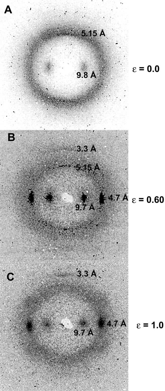
X-ray diffraction patterns for hagfish thread bundles strained in seawater. (A) Unstrained threads exhibited a typical “α-pattern,” whereas threads extended to a strain of 1.0 exhibited a typical “β-pattern” (C). Thread extended to a strain of 0.60 exhibited a mixed pattern, suggesting the presence of both α-helix and β-sheet structure (B). Diffraction maxima (dark spots) are labeled according to the molecular spacings (in Angstroms, Å) to which they correspond.
DISCUSSION
Hagfish threads are a good model for exploring IF mechanics
To be able to infer IF mechanical properties from the properties of hagfish threads, two conditions must be met. Namely, the IFs within the hagfish threads must exhibit high axial alignment, and hagfish thread strain must approximate IF strain. TEM images of developing threads suggest that the IFs are indeed highly aligned and run parallel to the long axis of the thread (Terakado et al., 1975; Downing et al., 1984). The x-ray diffraction patterns for unstretched threads presented here (Fig. 7 A) also indicate strong axial alignment parallel to the thread axis, given the small angular deviation of the 9.8 Å equatorial diffraction peak. The second condition requires that the IFs within the hagfish threads must not exhibit frictional sliding as the thread is strained, as this would uncouple the straining of the threads and their constituent IFs. Frictional sliding can be discounted in region I based on the ability of the threads to return to their original dimensions after straining. Furthermore, congo red and x-ray diffraction data demonstrate that plastic postyield straining of hagfish threads correlates with extension of IF proteins that make up the IFs. Although we can only speculate about the nature of the lateral adhesion that prevents slippage among adjacent IFs in hagfish threads, nonspecific electrostatic interactions are likely to be important given the extremely tight packing of IFs in these structures (Downing et al., 1984; Terakado et al., 1975). The properties of hagfish threads (i.e., IF bundles) have obvious relevance to the properties of keratin IF bundles that are commonly found in epithelial cells (Ma et al., 2001). Moreover, the above analysis also suggests that the properties of hagfish threads approximate the properties of the IFs that make them up.
IFs are flexible because of their low elastic modulus
Previous researchers have invoked the sliding of subfilaments within IFs to explain how IFs could be flexible in bending yet stiff in tension (Bray, 2001; Hohenadl et al., 1999; Howard, 2001). Our data indicate that IFs are over 200 times less stiff in tension than previously assumed, which simply abolishes the need to invoke subfilament sliding. Fig. 8 provides a more quantitative illustration of this point, in which Lp is plotted as a function of the number of freely sliding subfilaments within an IF. Using our measured value for the elastic modulus of IFs, and assuming no subfilament sliding within IFs during bending, the predicted Lp is 0.85 μm (Fig. 8 A), which is consistent with values based on light scattering and TEM measurements (Hohenadl et al., 1999; Howard, 2001). As the number of freely sliding subfilaments increases, Lp departs more and more from measured values. Furthermore, if Lp is calculated assuming that IFs are as stiff as keratins (Fig. 8 B), even the most extreme case of subfilament sliding (16 independent filaments composed of dimers joined end to end) predicts an Lp of ∼15 μm, which is more than an order of magnitude larger than measured values. The most parsimonious explanation therefore is that IFs are flexible in bending because of their low elastic modulus, and not because of subfilament sliding.
FIGURE 8.

The effect of subfilament sliding on the persistence length of IFs assuming a Young's modulus of 7.0 MPa (A) and 2 GPa (B). Persistence length was calculated assuming an IF diameter of 10 nm for the case of one subfilament, and holding the total cross-sectional area constant for all other cases. Note that under the assumption that IFs are as stiff as keratins, even the maximum amount of subfilament sliding predicts a persistence length an order of magnitude higher than measured values.
Elastomeric terminal domains dominate the low strain behavior of IFs
The low initial tensile modulus and high elasticity of hagfish threads strongly suggest that entropic mechanisms govern their low strain mechanical behavior. Entropic elasticity requires conformational freedom, but it is not at first obvious where within the threads this conformational freedom resides. With filament lengths typically much longer than Lp, it is clear that IFs themselves can generate entropic elasticity within entangled gel networks. However, it is unlikely that this attribute of IFs can account for the 6.4 MPa initial stiffness of hagfish threads. IF networks with an IF concentration of 1–2 mg/mL are capable of generating shear moduli on the order of only 1 Pa (Janmey et al., 1991). Such a mechanism is also unlikely given the fact that TEM (Downing et al., 1984; Terakado et al., 1975) and x-ray diffraction data (Fig. 7 A) indicate that the IFs within hagfish threads are strongly aligned parallel to the thread axis, and do not appear to possess conformational freedom.
Another possibility is that protofibrils, protofilaments, or coiled coils within the IFs give rise to the entropic elasticity. According to this hypothesis, these structures within the IF possess conformational freedom, and the initial modulus is governed by the decrease in entropy caused by straightening them out. Such a mechanism predicts that IF subfilaments, and therefore coiled coils within unstretched hagfish threads should exhibit a wide range of orientations as a result of their conformational freedom. The x-ray diffraction data contradict this prediction as well, and demonstrate that the coiled coils within unstretched hagfish threads exhibit strong axial alignment parallel to the thread axis (Fig. 7 A).
If neither the IFs nor the subfilaments within them are the source of the entropic elasticity, this leaves the terminal domains as the only place where the entropic elasticity can reside. According to this model, the terminal domain protein chains behave as elastomers in series with much stiffer coiled coils. If we assume that the dimer is the functional unit of IF mechanics and has the same mechanical behavior as the IFs, it is possible to develop a model that allows us to estimate the average tensile modulus of the terminal domains in region I (Fig. 9).
FIGURE 9.

Proposed mechanical behavior of IF dimers in mechanical region I. Assumptions of the model and flow of logic for the analysis are described in the text. The model suggests that in region I, the vast majority of the deformation occurs in highly extensible and low-stiffness terminal domains in series with stiff-coiled coils.
First we assume reasonable values for the coiled coil stiffness (2 GPa) (Howard, 2001), and the linear dimensions of the coiled coil (46.2 nm) (Parry and Steinert, 1999) and terminal domains (10.5 nm for sum of head and tail length). These dimensions were calculated by assuming that the terminal domains are ellipsoid in shape, with a length that is twice the diameter and depth. Terminal domain volume was calculated by inferring their mass from published hagfish slime IF sequence (Koch et al., 1995) and assuming a density of 1.38 g/cm3. We can then impose a hypothetical stress on the dimer—in this case the stress at the end of the region I, or the yield stress (σyield = 3.5 MPa). By assuming that the coiled coil and terminal domains are in series and possess similar cross-sectional areas, we can calculate the strain that this stress will cause in the coiled coil (ɛcc = 0.002). From the stress-strain behavior of hagfish threads in water, we also know the yield strain of the dimers (ɛIF ≈ 0.34). Using the relative linear proportions of the coiled coil and terminal domains, we can then calculate the strain that must occur in the terminal domains to give an overall IF strain of 0.34, which is ɛTD = 1.8. Knowing the stress and strain for the terminal domains allows us to calculate the average stiffness of these regions, ETD = σTD/ɛTD = 3.5 MPa/1.8 ≈ 2 MPa.
Such low stiffness and high extensibility are consistent with the terminal domains behaving elastomerically. This conclusion is supported by the approximate J-shape of the stress-strain curve in region I as well as the reversible nature of deformation in this region (Fig. 5, A and C). Furthermore, despite significant effort, the structure of IF terminal domains remains elusive (Parry and Steinert, 1999; Strelkov et al., 2001). The inability to define the structure of these domains may be due to the fact that they are elastomeric and therefore not confined to one conformation.
Molecular basis of hagfish thread IF mechanics
By synthesizing mechanical, congo red staining, and x-ray diffraction data with knowledge of IF protein architecture, it is possible to provide a reasonable account of the molecular events that underlie the mechanical behavior of hagfish thread IFs described here. The following model is given under the assumption that coiled coil IF protein dimers are the functional units of IFs and possess the same properties as all higher order structures up to the IFs themselves (Fig. 10). The low-modulus elastic behavior of region I can be attributed to the presence of elastomeric terminal domains in series with much stiffer coiled coils. By the end of region I, terminal domain strain is ∼1.8. In region II the stress is high enough to begin to extend α-helical domains in the coiled coils into β-strands. Alpha-helices are extended in this region at a fairly constant stress, as they are in the α-keratin “yield region” (Hearle, 2000). By the end of region II, coiled coils have been extended on average to a strain of ∼0.4. In region III, α-helices become more and more difficult to disrupt, causing a rise of both the stress and stiffness in this region. By the end of region III, coiled coils have been extended to their maximum theoretical strain of ∼1.25 (Hearle, 2000). According to the model developed in Fig. 10, the α→β transition should be complete by a strain of 1.4. At the end of region III, β-sheet and β-sheet crystal content are at their highest. Region IV therefore arises from the straining, slippage, and ultimate rupture of β-sheets and β-sheet crystals.
FIGURE 10.

Proposed mechanical behavior of IF dimers in regions I–III. In region I, deformation occurs almost exclusively in the terminal domains. In region II, α-helices within the coiled coil motif begin to extend into β-sheets (denoted by the crimped lines). By the end of region III, all of the coiled coil α-helices have been extended to β-sheets. Region IV corresponds to the straining, slippage, and ultimate rupture of β-sheets and β-sheet crystals.
The small number of strains examined do not allow us to provide a detailed account of the α→β transition from the x-ray data. However, in future experiments planned at the European Synchrotron Radiation Facility on the microfocus beam line ID13, we intend to study individual fibers and even to carry out real time diffraction measurements of the transition as a function of strain.
IF diversity may reflect mechanical diversity
Compared with the proteins that make up F-actin and microtubules, IF proteins are a diverse group, with the terminal domains accounting for most of the sequence diversity (Weber, 1999). Although the differences among terminal domains may correspond to differences in the assembly properties of IFs, or their ability to interact with each other or other proteins (Fuchs and Cleveland, 1998), our results suggest that differences among terminal domains may correspond to differences in the intrinsic mechanical properties of IFs, namely their elastic modulus (and therefore Lp) and extensibility. Indeed, differences in the viscoelastic properties of gels made from various IFs have been demonstrated (Bousquet et al., 2001; Hofmann and Franke, 1997; Janmey et al., 1991; Ma et al., 1999; Ma et al., 2001). If IF diversity corresponds to mechanical diversity, then tissue- and development-dependent IF expression may represent a tuning of the mechanical properties of cells to the loads they are likely to experience. While hagfish thread IFs have offered us a useful starting point for understanding IF mechanics, one of the challenges for the future will be to quantify the mechanical behavior of other IFs, ideally using atomic force microscopy.
IFs are mechanically distinct from F-actin and microtubules
The initial tensile modulus we report here for IFs is dramatically lower than for the other two cytoskeletal filaments, F-actin (∼300 times lower) and microtubules (∼150 times lower). Our results also suggest that IFs are far more extensible, with strains less than ∼0.35 being fully recoverable (i.e., the thread returns to its original length). This kind of extensibility is exceptional compared to F-actin and microtubules, which will break or yield at strains on the order of 0.01 (Kishino and Yanagida, 1988; Tsuda et al., 1996). High IF extensibility is consistent with TEM images of IFs exhibiting tight bends that simply would not be possible in F-actin or microtubules. In one particularly tight turn (radius of curvature of neutral axis = 17 nm) made by a vimentin filament (Hofmann et al., 1991), the material on the outside of the IF experiences a strain of ∼0.30. These results suggest that IFs perform a mechanical role in cells that is distinct from F-actin, the other tension-bearing element in the cytoskeleton (Ingber, 1993).
Implications for the function of IFs in living cells
Several of the tensile properties of IFs described here have important implications for the function of IFs in cells. First, our estimate of IF persistence length based on tensile mechanics provides an important confirmation of the Lp values obtained by light scattering (Hohenadl et al., 1999) and TEM (Howard, 2001). The low Lp (∼1 μm) of IFs relative to their typical length in cells (10–20 μm) suggests that networks of cytoplasmic IFs will form entropic gels within the confines of a cell (Gittes et al., 1993). In this way, IFs are likely to contribute an extremely soft elasticity to cells.
Whereas F-actin and microtubules can only impart soft elasticity to cells via their participation in entropic gels, the tensile behavior of IFs described here suggests that IFs may also contribute to cell elasticity via direct loading in tension (i.e., stretching). If individual IFs can deform elastically to a strain of 0.34 as suggested here, then the direct stretching of IFs or IF bundles in cells may represent an important mechanism whereby cells withstand and passively recover from dramatic loads and deformations.
When stretched beyond their elastic range, IFs exhibit an enormous capacity for plastic deformation, much of which can be attributed to the α→β transition of IF proteins. Although IFs strained past their yield point will not recover to their original length, the large amounts of energy they absorb could potentially avert catastrophic rupture of the cell. Cell deformations large enough to plastically deform IFs may be rare, but if such an event were to occur, the conformational change that IFs undergo could be used by cells as a cue that cytoskeletal integrity has been compromised. Others have suggested that IFs could play a role in mechanotransduction. Lazarides (1980) proposed that IFs may channel mechanical stimuli directly to the nucleus. Our work raises a different possibility; the appearance of stable β-sheets within IFs triggers cellular programs of cytoskeletal repair or even apoptosis, depending on the severity of the damage.
Gel entropy versus tensegrity
Although biophysicists' understanding of the cytoskeleton's contribution to cell mechanics continues to improve, a single comprehensive model has yet to be agreed upon. One controversy surrounds the mechanisms by which cytoskeletal filaments resist cell deformation. The gel entropy theory postulates that dynamic cytoskeletal filaments make up a cross-linked and entangled, viscoelastic network that resists deformations via both viscous effects as well as a decrease in the conformational entropy of the network (Heidemann et al., 2000). In contrast, the tensegrity theory imagines the cytoskeleton as a more static structure, in which discontinuous compressive struts (i.e., MTs) are embedded in a continuous network of pre-strained tension elements. In this way, tensegrity posits that the cytoskeleton resists deformation via direct loading (either in compression or tension) of the cytoskeletal filaments, with entropic changes of the network playing little or no role.
The mechanical data presented here clearly cannot resolve the gel entropy/tensegrity debate, although they do offer some insights. Our confirmation of the low Lp of IFs supports the idea that IFs may form viscoelastic entropic gels in cells. On the other hand, the elasticity and low initial stiffness of IF bundles or IFs suggests that they may also impart elasticity to cells via direct tensional loading. A major criticism of tensegrity has been that it requires an elastic, low stiffness element in order for it to model the soft viscoelasticity of cells, and no such element has been identified to date. In light of the data presented here, IF bundles or IFs could represent this elastic, low stiffness structural element in cells. Of course IFs cannot simultaneously participate in an entropic gel network, and be loaded directly in tension. Its contribution, therefore, depends upon whether it possesses conformational freedom (gel entropy) or is taut and loaded in tension (tensegrity).
The propensity of a given IF to form bundles in vivo is relevant here, because tightly bound bundles will exhibit much higher persistence lengths and flexural stiffness than unbundled IFs. IFs differ in their tendency to form bundles (Ma et al., 2001), thus bundling may be an important factor in determining whether a given IF functions in entropic gels or is loaded directly in tension in vivo. Furthermore, IFs that are anchored at one end by desmosomes may be functionally anchored at another site via tight bundling with other IFs. This arrangement offers another mechanism by which IFs may be directly loaded in tension in addition to simply spanning from desmosome to desmosome.
CONCLUSIONS
Experiments with hagfish threads suggest that hydrated intermediate filament bundles differ dramatically from hard α-keratins in their mechanical properties. Their low initial stiffness predicts an IF persistence length of 0.85 μm. These results confirm the low persistence lengths reported for IFs from light scattering and TEM data, and do away with the need to invoke subfilament sliding within IFs during bending. The low persistence length also suggests that IFs can form entropic gels within cells. Unlike F-actin and microtubules, which are relatively rigid, IFs can extend reversibly up to strains of 0.3–0.4, suggesting that cytoplasmic IFs or IF bundles may be loaded and stretched to relatively large strains as part of their normal function. At higher strains, IF proteins undergo an irreversible α→β transition as suggested by congo red staining and x-ray diffraction. Although such plastic deformation of IFs appears to be irreversible and therefore damaging, the large amounts of energy absorbed by IFs may spare cells from catastrophic rupture. Furthermore, the appearance of stable β-sheet structures in cytoplasmic IFs after severe cell deformations may play a role in the onset of programs of cellular repair or even apoptosis.
Acknowledgments
We thank Joelle Harris, Nathan Webb, Anne Todgham, Bev Wicks, Tara Law, Christine Ortlepp, William Megill, and Todd Gillis for help in the collection and transport of hagfish. Margo Lille, Ken Savage, Paul Guerette, Marvin Braun, Scott Rapoport, Bob Shadwick, and Wayne Vogl all provided valuable feedback on the manuscript. Manfred Burghammer provided superb technical assistance at the ID13 beamline. We acknowledge the use of CCP13 software (http://www.ccp13.ac.uk) and of the FIT2D package of Andy Hammersley.
This work was supported by a National Science and Engineering Research Council of Canada operating grant to J.M.G. and a Killam fellowship to D.S.F. Travel to Grenoble was paid for in part by a Canadian Society of Zoologists research grant to D.S.F.
References
- Alberts, B., D. Bray, J. Lewis, M. Raff, K. Roberts, and J. D. Watson. 1994. Molecular Biology of the Cell. Garland, New York.
- Beckwith, T. G., R. D. Marangoni, and J. H. Lienhard. 1993. Mechanical Measurements. Addison-Wesley, New York.
- Bendit, E. G. 1960. A quantitative x-ray diffraction study of the alpha-beta transformation in wool keratin. Text. Res. J. 30:547–555. [Google Scholar]
- Bousquet, O., L. L. Ma, S. Yamada, C. H. Gu, T. Idei, K. Takahashi, D. Wirtz, and P. A. Coulombe. 2001. The nonhelical tail domain of keratin 14 promotes filament bundling and enhances the mechanical properties of keratin intermediate filaments in vitro. J. Cell Biol. 155:747–753. [DOI] [PMC free article] [PubMed] [Google Scholar]
- Bray, D. 2001. Cell Movements: From Molecules to Motility. Garland, New York.
- Cusack, S., H. Belrhali, A. Bram, M. Burghammer, A. Perrakis, and C. Riekel. 1998. Small is beautiful: protein micro-crystallography. Nat. Struct. Biol. 5:634–637. [DOI] [PubMed] [Google Scholar]
- Downing, S. W., W. L. Salo, R. H. Spitzer, and E. A. Koch. 1981a. The hagfish slime gland: a model system for studying the biology of mucus. Science. 214:1143–1145. [DOI] [PubMed] [Google Scholar]
- Downing, S. W., R. H. Spitzer, E. A. Koch, and W. L. Salo. 1984. The hagfish slime gland thread cell. I. A unique cellular system for the study of intermediate filaments and intermediate filament-microtubule interactions. J. Cell Biol. 98:653–669. [DOI] [PMC free article] [PubMed] [Google Scholar]
- Downing, S. W., R. H. Spitzer, W. L. Salo, S. D. Downing, L. J. Saidel, and E. A. Koch. 1981b. Hagfish slime gland thread cells: organization, biochemical features, and length. Science. 212:326–327. [DOI] [PubMed] [Google Scholar]
- Felgner, H., R. Frank, and M. Schliwa. 1996. Flexural rigidity of microtubules measured with the use of optical tweezers. J. Cell Sci. 109:509–516. [DOI] [PubMed] [Google Scholar]
- Fernholm, B. 1981. Thread cells from the slime glands of hagfish (Myxinidae). Acta Zool. 62:137–145. [Google Scholar]
- Ferry, J. D. 1941. A fibrous protein from the slime of the hagfish. J. Biol. Chem. 138:263–268. [Google Scholar]
- Fraser, R. D., T. P. MacRae, and G. E. Rogers. 1972. Keratins: Their Composition, Structure, and Biosynthesis. I. N. Kugelmass, editor. Charles C. Thomas, Springfield, IL.
- Fuchs, E., and D. W. Cleveland. 1998. A structural scaffolding of intermediate filaments in health and disease. Science. 279:514–519. [DOI] [PubMed] [Google Scholar]
- Gittes, F., B. Mickey, J. Nettleton, and J. Howard. 1993. Flexural rigidity of microtubules and actin filaments measured from thermal fluctuations in shape. J. Cell Biol. 120:923–934. [DOI] [PMC free article] [PubMed] [Google Scholar]
- Gosline, J. M., C. C. Pollak, P. A. Guerette, A. Cheng, M. E. DeMont, and M. W. Denny. 1994. Elastomeric network models for the frame and viscid silks from the orb web of the spider Araneus diadematus. In: Silk Polymers. American Chemical Society, Washington, DC. 329–40.
- Hearle, J. W. 2000. A critical review of the structural mechanics of wool and hair fibres. Int. J. Biol. Macromol. 27:123–138. [DOI] [PubMed] [Google Scholar]
- Heidemann, S. R., P. Lamoureaux, and R. E. Buxbaum. 2000. Opposing views on tensegrity as a structural framework for understanding cell mechanics. J. Appl. Physiol. 89:1670–1678. [PubMed] [Google Scholar]
- Hofmann, I., and W. W. Franke. 1997. Heterotypic interactions and filament assembly of type I and type II cytokeratins in vitro: viscometry and determinations of relative affinities. Eur. J. Cell Biol. 72:122–132. [PubMed] [Google Scholar]
- Hofmann, I., H. Herrmann, and W. W. Franke. 1991. Assembly and structure of calcium-induced thick vimentin filaments. Eur. J. Cell Biol. 56:328–341. [PubMed] [Google Scholar]
- Hohenadl, M., T. Storz, H. Kirpal, K. Kroy, and R. Merkel. 1999. Desmin filaments studied by quasi-elastic light scattering. Biophys. J. 77:2199–2209. [DOI] [PMC free article] [PubMed] [Google Scholar]
- Howard, J. 2001. Mechanics of Motor Proteins and the Cytoskeleton. Sinauer Associates, Sunderland, MA.
- Ingber, D. E. 1993. Cellular tensegrity: defining new rules of biological design that govern the cytoskeleton. J. Cell Sci. 104:613–627. [DOI] [PubMed] [Google Scholar]
- Janmey, P. A., U. Euteneuer, P. Traub, and M. Schliwa. 1991. Viscoelastic properties of vimentin compared with other filamentous biopolymer networks. J. Cell Biol. 113:155–160. [DOI] [PMC free article] [PubMed] [Google Scholar]
- Kishino, A., and T. Yanagida. 1988. Force measurements by micromanipulation of a single actin filament by glass needles. Nature. 334:74–76. [DOI] [PubMed] [Google Scholar]
- Knight, D. P., M. M. Knight, and F. Vollrath. 2000. Beta transition and stress-induced phase separation in the spinning of spider dragline silk. Int. J. Biol. Macromol. 27:205–210. [DOI] [PubMed] [Google Scholar]
- Koch, E. A., R. H. Spitzer, R. B. Pithawalla, F. A. Castillos 3rd, and D. A. Parry. 1995. Hagfish biopolymer: a type I/type II homologue of epidermal keratin intermediate filaments. Int. J. Biol. Macromol. 17:283–292. [DOI] [PubMed] [Google Scholar]
- Koch, E. A., R. H. Spitzer, R. B. Pithawalla, and D. A. Parry. 1994. An unusual intermediate filament subunit from the cytoskeletal biopolymer released extracellularly into seawater by the primitive hagfish (Eptatretus stoutii). J. Cell Sci. 107:3133–3144. [DOI] [PubMed] [Google Scholar]
- Kojima, H., A. Ishijima, and T. Yanagida. 1994. Direct measurement of stiffness of single actin filaments with and without tropomyosin by in vitro nanomanipulation. Proc. Natl. Acad. Sci. USA. 91:12962–12966. [DOI] [PMC free article] [PubMed] [Google Scholar]
- Kurachi, M., M. Hoshi, and H. Tashiro. 1995. Buckling of a single microtubule by optical trapping forces: direct measurement of microtubule rigidity. Cell Motil. Cytoskeleton. 30:221–228. [DOI] [PubMed] [Google Scholar]
- Lazarides, E. 1980. Intermediate filaments as mechanical integrators of cellular space. Nature. 283:249–256. [DOI] [PubMed] [Google Scholar]
- Ma, L., J. Xu, P. A. Coulombe, and D. Wirtz. 1999. Keratin filament suspensions show unique micromechanical properties. J. Biol. Chem. 274:19145–19151. [DOI] [PubMed] [Google Scholar]
- Ma, L., S. Yamada, D. Wirtz, and P. A. Coulombe. 2001. A 'hot-spot' mutation alters the mechanical properties of keratin filament networks. Nat. Cell Biol. 3:503–506. [DOI] [PubMed] [Google Scholar]
- Magin, T. M., M. Hesse, and R. Schroder. 2000. Novel insights into intermediate-filament function from studies of transgenic and knockout mice. Protoplasma. 211:140–150. [Google Scholar]
- Parry, D. A., and P. M. Steinert. 1999. Intermediate filaments: molecular architecture, assembly, dynamics and polymorphism. Q. Rev. Biophys. 32:99–187. [DOI] [PubMed] [Google Scholar]
- Pollock, C. M., and R. E. Shadwick. 1994. Allometry of muscle, tendon, and elastic energy storage capacity in mammals. Am. J. Physiol. 266:R1022–R1031. [DOI] [PubMed] [Google Scholar]
- Porter, R. M., A. M. Hutcheson, E. L. Rugg, R. A. Quinlan, and E. B. Lane. 1998. cDNA cloning, expression, and assembly characteristics of mouse keratin 16. J. Biol. Chem. 273:32265–32272. [DOI] [PubMed] [Google Scholar]
- Puchtler, H., F. S. Waldrop, and S. N. Meloan. 1985. A review of light, polarization and fluorescence microscopic methods for amyloid. Appl. Pathol. 3:5–17. [PubMed] [Google Scholar]
- Riekel, C. 2000. New avenues in x-ray microbeam experiments. Rep. Prog. Phys. 63:233–262. [Google Scholar]
- Strelkov, S. V., H. Herrmann, N. Geisler, A. Lustig, S. Ivaninskii, R. Zimbelmann, P. Burkhard, and U. Aebi. 2001. Divide-and-conquer crystallographic approach towards an atomic structure of intermediate filaments. J. Mol. Biol. 306:773–781. [DOI] [PubMed] [Google Scholar]
- Terakado, K., M. Ogawa, and Y. Hashimoto. 1975. Ultrastructure of the thread cells in the slime gland of Japanese hagfishes, Paramyxine atami and Eptatretus burgeri. Cell Tissue Res. 159:311–323. [DOI] [PubMed] [Google Scholar]
- Tsuda, Y., H. Yasutake, A. Ishijima, and T. Yanagida. 1996. Torsional rigidity of single actin filaments and actin-actin bond breaking force under torsion measured directly by in vitro micromanipulation. Proc. Natl. Acad. Sci. USA. 93:12937–12942. [DOI] [PMC free article] [PubMed] [Google Scholar]
- Wang, H., D. A. D. Parry, L. N. Jones, W. W. Idler, L. N. Marekov, and P. M. Steinert. 2000a. In vitro assembly and structure of trichocyte keratin intermediate filaments: a novel role for stabilization by disulfide bonding. J. Cell Biol. 151:1459–1468. [DOI] [PMC free article] [PubMed] [Google Scholar]
- Wang, J., A. Karabinos, J. Schunemann, D. Riemer, and K. Weber. 2000b. The epidermal intermediate filament proteins of tunicates are distant keratins; a polymerisation-competent hetero coiled coil of the Styela D protein and Xenopus keratin 8. Eur. J. Cell Biol. 79:478–487. [DOI] [PubMed] [Google Scholar]
- Weber, K. 1999. Evolutionary aspects of IF proteins. In Guidebook to the Cytoskeletal and Motor Proteins. T. Kreis and R. Vale, editors. Oxford University Press, Oxford. 291–3.