

Abstract
Cells and biomolecules exposed to blood circulation experience hydrodynamic forces that affect their function. We present a methodology to estimate fluid forces and force loading rates applied on cellular aggregates, cell-surface proteins, and soluble molecules. Low Reynolds-number hydrodynamic theory is employed. Selected results are presented for biological cases involving platelets, neutrophils, tumor cells, GpIb-like cell-surface receptors, and plasma von Willebrand factor (vWF)-like soluble proteins. Calculations reveal the following: 1), upon application of constant linear shear, cell aggregates and biomolecules experience time-varying forces due to their tumbling motion. 2), In comparison to neutrophil homotypic aggregates, the maximum force applied on neutrophil-platelet aggregates is approximately threefold lower. Thus, alterations in cell size may dramatically alter adhesion molecule requirement for efficient cell binding. Whereas peak forces on homotypic cell doublets are tensile, shear forces dominate in heterotypic doublets with radius ratio <0.3. 3), The peak forces on platelet GpIb and von Willebrand factor are of comparable magnitude. However, they are orders-of-magnitude lower than those applied on intercellular bonds. Charts are provided to rapidly evaluate the magnitude of hydrodynamic force and rotation time-period occurring in any given experiment. The calculation scheme may find application in studies of vascular biology and receptor biophysics.
INTRODUCTION
Flowing blood plays an important role in both initiating and regulating biological processes in circulation. For example, high shear stresses have been shown to contribute to platelet activation, and subsequent aggregation and secretion in models of arterial thrombosis (Kroll et al., 1996; Shankaran et al., 2003). This process is triggered by the binding of a plasma protein von Willebrand factor (vWF) to the platelet receptor Glycoprotein Ib (GpIb). The critical role of vWF and GpIb suggests that one or both of these molecules may undergo structural/functional changes upon application of fluid shear (Kroll et al., 1996). Gene expression and protein synthesis in endothelial cells is also altered upon application of arterial shear stresses (Davies, 1995; Nollert et al., 1992). In addition to controlling cellular activation in the above examples, hydrodynamic shear also controls the rates of cell-cell collision, deformation, receptor-ligand bond formation, and adhesion. In a prominent example, fluid shear has been shown to allow optimal L-selectin-mediated leukocyte rolling only above a minimum-threshold shear rate (Finger et al., 1996; Taylor et al., 1996).
In this article, we apply low Reynolds-number hydrodynamic theory to study the nature and magnitude of forces applied on cellular aggregates, soluble molecules, and cell-surface receptors. Currently, well-defined solutions exist for the estimation of forces applied on particles localized near a substrate under fluid flow (Goldman et al., 1967). This analysis has aided estimation of the biophysical properties of receptor-ligand bonds formed by adhesion molecules belonging to the selectin family (Alon et al., 1995; Smith et al., 1999). Equations also exist for analytical computation of the hydrodynamic forces applied on aggregates composed of two equal-sized particles (Arp and Mason, 1977; Tha and Goldsmith, 1986). This has been applied in studies of neutrophil, platelet, and red blood cell homotypic aggregation (Goldsmith et al., 2000, 2001; Shankaran and Neelamegham, 2001b; Tees et al., 1993). Here, we present methods for the analytical computation of fluid forces on doublets composed of unequal-sized particles separated by a finite distance. We are interested in this problem since, as elaborated later, many biological particles can be represented as a pair of (un)equal spheres linked by a rigid tether. We apply this methodology to estimate the magnitude and loading rates of forces applied on intercellular bonds linking cellular aggregates, including neutrophil-platelet, neutrophil-neutrophil, neutrophil-tumor, platelet-platelet, and platelet-tumor aggregates. Such homotypic and heterotypic aggregates in vivo often regulate the progress of inflammatory diseases, cardiovascular ailments, and cancer metastasis. Besides analyzing cell aggregation, this methodology also allows estimation of the forces applied on microdomains of cell-surface receptors like GpIb on platelets, and on soluble molecules like vWF. Our results illustrate the importance of particle size ratio in determining both the direction and magnitude of force applied. Such analysis is important since it will allow us to: 1), translate data from single molecule studies (e.g., atomic-force microscopy measurements) to predict ensemble behavior in suspension; 2), design appropriate in vitro experimental systems to apply the range of hydrodynamic forces that are relevant in vivo; and 3), understand the fundamental mechanisms of fluid flow-initiated biological phenomena.
METHODS
We consider the hydrodynamic interaction between a pair of interacting, unequal-sized spheres of radii a1 and a2, the surfaces of which are separated by a tether of length d (Fig. 1). The center-to-center separation distance between the spheres is a1 + a2 + d. By convention, the larger sphere is labeled 1 and the smaller sphere is 2. This doublet is assumed to behave as a rigid dumbbell, where the individual spheres do not undergo free rotation about the tether. It is subjected to a linear shear flow. In particular, a simple shear of magnitude G with equal extensional and rotational components is chosen. In this analysis, the key geometric parameters that determine the hydrodynamic behavior of the doublet are: 1), the radius of the larger sphere, a1; 2), the radius ratio λ = a2/a1; and 3) the dimensionless separation distance, δ = d/a1. Other flow parameters that influence the magnitude of applied force and force loading rates are the shear rate, G; the orientation of the dumbbell axis with respect to the flow direction; and the fluid viscosity, μ.
FIGURE 1.

Coordinate system. Biological particles are modeled as a pair of (un)equal spheres of radii a1 and a2 (a1 > a2) separated by a rigid tether of length d. Space-fixed coordinate system is designated xi. x3 coincides with the direction of fluid flow, x2 is the direction of the velocity gradient, and x1 is the vorticity axis. The origin O lies at the midpoint of the line joining the centers of the two spheres. Xi describes the particle-fixed coordinates. X3 lies along the line joining the centers of the two spheres. It is directed toward the larger sphere. X2 is coplanar with the x1–x3 plane, and X1 is perpendicular to X2 and X3. (θ1, φ1) and (θ2, φ2) are polar and azimuthal angles with respect to the axes x1 and x2, respectively. (Figure adapted from Arp and Mason, 1977.)
The key assumptions made are as follows:
We employ Stokes hydrodynamic theory for our calculations. This is a valid assumption under the low-particle Reynolds-number or creeping-flow conditions that are typical in vivo in the microcirculation and for most experiments in vitro (Fung, 1984).
We assume that cellular doublets behave as rigid dumbbells. In this regard, although it is possible to consider the free or partially damped rotation of the spheres comprising the doublet based on previous work (Adler, 1981; van de Ven and Mason, 1976), this type of motion is likely to be more important as cells approach each other and collide. After collision and bond formation the doublets more closely resemble a rigid dumbbell, with little or no rotary motion of the cells about the bond. This assumption is supported by video-microscopy observations that red blood cell and neutrophil doublets behave as rigid dumbbells after cell-cell collision (Goldsmith et al., 2001; Tees et al., 1993). Cell-surface receptors are also modeled as a small sphere linked to the cell via a tether. This is supported by electron microscopy observations that suggest that a number of cell-surface receptors, especially those involved in cell adhesion, resemble beads tethered to the cell surface (Drescher et al., 1996; Fox et al., 1988; Ushiyama et al., 1993). Some soluble proteins in suspension that are either dimers or that have structural symmetry also lend themselves to this simplified model of two spheres linked by a tether (Fowler et al., 1985).
Effects of rotary Brownian motion are neglected in our calculations. Although this feature affects the trajectory (not the force) of soluble molecules at low shear rates, it has a negligible effect on the forces and loading rates of cell doublets and cell-surface receptors (see Discussion).
The fluid is considered to be Newtonian. This is a good assumption in vitro where dilute cell suspensions are subjected to shear. Whole blood, however, behaves as a non-Newtonian fluid below shear rates of ∼100/s and it has a high density of red blood cells. Further, blood viscosity may vary in the radial direction in vivo, due to the inward migration of erythrocytes from the vessel wall resulting in a cell-depleted peripheral plasma layer. Despite these limitations, we suggest that as a starting point, a reasonable manner in which this complex fluid can be handled is by incorporating a shear-rate-dependent local viscosity in Eq. 2 below, while continuing to use the force coefficients provided here.
Finally, we only consider the case of a linear shear field, the rationale being that irrespective of the exact nature of the flow encountered, in the length scale of molecular/cellular size, the flow can be approximated to a linear shear. Thus the results provided here can be applied to any general flow field by substituting the local value of the shear rate G, in the expressions for the hydrodynamic force (Shankaran and Neelamegham, 2001a,b).
Hydrodynamic forces applied on the spheres of a rigid dumbbell in linear shear flow
The hydrodynamic force felt by a pair of neutrally buoyant interacting spheres subjected to low Reynolds-number flow can be written as (Brenner and O'Neill, 1972)
 |
(1) |
where ℱ is the 1 × 12 force-torque vector, ℛ is the 12 × 12 grand resistance matrix, 𝒰 is the 1 × 12 relative velocity-spin vector, Φ is the 12 × 12 shear resistance matrix, and ℰ is a 1 × 12 shear vector. For convenience, we choose to solve this equation in the particle-fixed coordinates (Xi) (Fig. 1). In the above expression, ℛ and Φ are flow-independent resistance matrices that are functions of a1, δ, and λ. Our computations of these matrices are based on the work of Jeffrey and colleagues (Jeffrey, 1992; Jeffrey and Onishi, 1984), and are accurate for nontouching spheres (δ > 0) with λ ≥ 0.01, although reasonable estimates are obtained for λ down to 0.002 (see Eqs. A5 and A6 in Appendix, section A1). ℰ is obtained in a straightforward fashion from the rate-of-strain tensor (Eq. A7, Appendix, section A1). The relative velocity-spin vector 𝒰 is determined using knowledge of doublet motion in the linear shear field (Nir and Acrivos, 1973), along with net force and torque balance equations (Eq. A8, Appendix, section A1). Once the parameters on the right-hand side of the above equation are defined, the force applied on the individual spheres is computed in the particle-fixed coordinates. The normal force (Fn) acting along the line joining the centers of the two spheres forming the dumbbell, and shear force (Fs) acting perpendicular to this direction, can then be readily evaluated and expressed in the form (Appendix, section A1) of
 |
(2) |
where αn and αs are force coefficients that are functions solely of the dumbbell geometry (δ and λ). θ1, φ1, θ2, and φ2 are angles describing the orientation of the dumbbell with respect to the flow (Fig. 1). The maximum value of Fn is αn at φ1 = (2n + 1)π/4 and θ1 = π/2, and the highest value of Fs is αs
 at φ1 = nπ/2 and θ1 = π/2 (which is equivalent to θ2 = nπ for all φ2, and θ2 = (2n + 1)π/2 when φ2 = nπ). It should be noted that Eq. 2 is of the same form as that reported by Tha and Goldsmith (1986) for the case of equal spheres. Here, in the force equation, the prefactors αn and αs, in addition to being functions of δ, are also dependent on λ—which enables the extension of the equation to the case of unequal spheres.
Dumbbell rotation and dynamic force loading rate
A rigid dumbbell suspended in shear flow rotates about a point termed the center of free rotation, CR. Thus, the orientation of the doublet axis with respect to the flow changes with time, t. This rotation of the doublet in a linear shear field is described by Arp and Mason (1977) and Jeffery (1922) as
 |
(3) |
Here,  is the equivalent spheroidal axis ratio of the doublet, which is solely a function of the particle geometry.
  is numerically computed as discussed in Appendix, section A2. The time-period T of doublet rotation is then computed using
  Here, TG/2π is referred to as dimensionless time-period.
Due to doublet rotation, the hydrodynamic force applied on the particle varies with time. Combining Eqs. 2 and 3, it can be shown that the maximum rates of normal and shear force loading are given by Eq. A13. The maximum normal force loading rate occurs at θ1 = π/2 and φ1 = nπ, and the maximum shear force loading rate occurs at θ1 = π/2 and a φ1-value that is a function of 
Application of Stokes law to compute forces felt by cell-surface receptors
A cell-surface receptor is modeled as a small sphere of radius a2 (sphere 2) attached to the larger cell of radius a1 (sphere 1) via a tether of length d. The normalized distance of the center of sphere 2 from the surface of sphere 1 is ɛ = (d + a2)/a1. If sphere 2 in the doublet is very small, then it would be the dimensions of sphere 1 that primarily control the motion of the doublet. Also, the disturbance to local fluid flow due to sphere 2 can be neglected. For this case, Stokes law can be applied to compute the force felt by a stationary sphere 2 placed in the velocity disturbance field created by sphere 1. The steps involved for calculation of the velocity disturbance field about sphere 1 in a linear shear field and the application of Stokes law for force computations are discussed in Appendix, section A3. It is shown here that for λ≪1, ɛ≪1 (small sphere 2 close to the surface of sphere 1), the normal and shear forces applied on sphere 2 are quantified by
 |
(4) |
The normal force is maximized at φ1 = (2n + 1)π/4 and θ1 = π/2, where it equals (45/2)πμGa1a2ɛ2. The shear force is maximized at φ1 = nπ/2 and θ1 = π/2, where it takes the value 15πμGa1a2(ɛ −2ɛ2). It is noted that Eqs. 2 and 4 have similar forms with respect to their orientation dependence. A methodology to include the disturbance velocity due to sphere 2 is also briefly discussed in Appendix, section A3.
RESULTS
We evaluate the direction, magnitude, and loading rates of hydrodynamic forces applied on cell doublets, cell-surface receptors, and soluble proteins subjected to fluid shear under physiologically relevant conditions. Cases listed in Table 1 are considered.
TABLE 1.
Radii and separation distances for biomolecules and cells
| 1. PMN-PMN | 2. Platelet-platelet | 3. PMN-platelet | 4. PMN-tumor cell | 5. Platelet-tumor cell | 6. Platelet receptor | 7. PMN receptor | 8. vWF | |
|---|---|---|---|---|---|---|---|---|
| a1* (μm) | 3.75–7.5 (4.5) | 1.0–2.0 (1.5) | 3.75–7.5 (4.5) | 6.0–10.0 (8.0) | 6.0–10.0 (8.0) | 1.0–2.0 (1.5) | 3.75–7.5 (4.5) | 0.013–0.026 (0.013) |
| a2* (μm) | 3.75–7.5 (4.5) | 1.0–2.0 (1.5) | 1.0–2.0 (1.5) | 3.75–7.5 (4.5) | 1.0–2.0 (1.5) | 0.002–0.005 (0.0035) | 0.002–0.005 (0.0035) | 0.013–0.026 (0.013) |
| d† (μm) | 0.03–0.63 (0.63) | 0.03–4.03 (4.03) | 0.03–2.33 (2.33) | 0.03–0.63 (0.63) | 0.03–2.33 (2.33) | 0.015–0.03 (0.03) | 0.015–0.315 (0.315) | 0.094–0.188 (0.094) |
| λ | 0.5–1.0 | 0.5–1.0 | 0.133–0.533 | 0.375–0.8 | 0.1–0.3333 | 0.001–0.005 | 0.0003–0.0013 | 0.5–1.0 |
| δ | 0.004–0.168 | 0.015–4.03 | 0.004–0.621 | 0.003–0.105 | 0.003–0.388 | 0.0075–0.03 | 0.002–0.084 | 3.62–14.46 |
Table presents radius (a1, a2), separation distance (d), radius ratio (λ = a2/a1), and dimensionless separation distance (δ = d/a1) for biological species 1–8. Values in parentheses denote typical radii and separation distances used in calculations for Figs. 2 and 5.
Cell sizes are based on Ballard (1987) and Enderle et al. (2000). Tumor cell sizes vary depending upon tissue of origin. Lower limit of vWF globular domain size corresponds to unimers (Fowler et al., 1985). The upper limit for vWF is a hypothetical value for multimeric vWF. Values for platelet and PMN receptor dimensions are from Fox et al. (1988) and Ushiyama et al. (1993).
A typical receptor length of 30 nm is employed in all cases (Becker et al., 1989; Fahrig et al., 1993; Fox et al., 1988; Patel et al., 1995; Ushiyama et al., 1993). Cells are assumed to have a 15-nm glycocalyx (Patel et al., 1995; White, 1984), thus reducing the lower limit of receptor length (d) to 15 nm. It is noted that glycocalyx height measurement is an active area of research, and various treatments may alter this height (van den Berg et al., 2003). The lower limit of the separation distance between cells composing aggregates involving PMNs and platelets assumes that the receptor is located on the cell body. The upper limit assumes that receptors and ligands are localized at the tip of 0.3-μm-long microvilli in the case of neutrophils (Erlandsen et al., 1993) and tumor cells, and at the end of a 2-μm pseudopod in the case of activated platelets (White, 1984). The lower limit of separation for vWF is from Fowler et al. (1985).
Time-variant forces applied on cell doublets and biomolecules in linear shear flow
Fig. 2 depicts the periodic variation in normal (Fn) and shear force (Fs) applied on a rigid dumbbell subjected to a linear shear. Whereas Fn contributes to cycles of compressive (Fn < 0) and tensile (Fn > 0) loading, Fs applies lateral/tangential stresses. For these computations, the dimensions of the cells/molecules are based on the typical sizes and separation distances provided in parentheses in Table 1. For each particle, the dumbbell was set to rotate in the x2–x3 plane (θ1 = π/2), starting with an initial orientation of φ1 = 0 at t = 0. Following this time, Eq. 3 was used to predict the dumbbell orientation at any instant of time, and the applied hydrodynamic force at that orientation was evaluated using Eq. 2.
FIGURE 2.

Hydrodynamic force applied on cell doublets, cell-surface receptors, and soluble molecules. Cases considered are (A) PMN-PMN doublets, (B) platelet-tumor doublets, (C) platelet surface receptors, and (D) vWF-like soluble molecules. Dumbbells rotating in the x2–x3 plane (θ1 = π/2) were examined starting with the initial coordinate φ1 = 0 at t = 0. The shear rate was 600/s, fluid viscosity was 1 cP and other parameter values correspond to typical values in Table 1. The magnitude of normal (continuous line) and shear forces (dashed line) are plotted as a function of time. Cartoons (a–e) correspond to orientations of maximum shear (a, c, e), tension (b), and compression (d) during doublet half-rotation. Points corresponding to each of these orientations are labeled in the individual panels.
The results demonstrate that:
Fn is the dominant force applied on PMN-PMN doublets, and it exceeds Fs by approximately threefold (Fig. 2 A). Thus, the ability of receptor-ligand bonds to withstand tensile loading is likely to determine the rate at which these doublets form and break up under shear.
For platelet-tumor cell heterotypic doublets (Fig. 2 B), the peak Fn and Fs are of comparable magnitudes. Since the maximum force applied on platelet-tumor cell aggregates is ∼3× lower than the forces on PMN-PMN doublets, it may be expected that fewer bonds or bonds with lesser strength would be sufficient to hold these aggregates together.
For the case of platelet surface receptors (Fig. 2 C), in sharp contrast to cell doublets, the peak Fs is ∼30× higher than Fn. Further, the magnitude of forces applied are ∼104× lower than that applied on cell-cell bonds.
The magnitude of force applied on soluble vWF protomers (Fig. 2 D) is similar to that on platelet surface receptors, although, in this case, the peak Fn exceeds the peak Fs by ∼20-fold. Thus, fluid flow primarily exerts extensional forces on vWF-like soluble molecules.
Although the magnitude of force applied on the particles above varies by several orders of magnitude depending on particle geometry, variations in particle rotation time-period are less drastic. The rotation time-period of these objects varied as: vWF (66 ms) > PMN-PMN doublet (27 ms) > platelet-tumor cell doublet (21 ms) ≈ platelet surface receptors (21 ms).
Overall, the results demonstrate that the geometry of the dumbbell, quantified by the radius ratio (λ = a1/a2) and the separation distance (δ = d/a1), dictate the magnitude and direction of applied hydrodynamic forces and force loading rates.
Magnitude of hydrodynamic force as a function of particle geometry
One of our primary objectives is to provide figures/charts that will allow the reader to rapidly and accurately evaluate the magnitude of hydrodynamic force applied in any given experiment. With regard to this goal, we computed the normal (αn) and shear force (αs) coefficients for dumbbells as a function of particle geometric parameters, δ and λ (Fig. 3, A and B). These figures provide force coefficient values for cell doublets, receptors, and soluble molecules by solution of the complete problem of two unequal interacting spheres as discussed in Methods. When combined with Eq. 2, knowledge of the coefficients readily yields the magnitude of the hydrodynamic force. Our results indicate that below a dimensionless separation distance δ of 0.1, the force coefficients are independent of separation distance provided λ > 0.05. Cell doublets typically satisfy this criterion. In the case of soluble proteins, however, δ may be >0.1 (Table 1). In this range, since normal forces increase and shear forces decrease with increasing δ, it may be expected that the dominant forces on soluble molecules are extensional in nature. In the case of cell-surface receptors, λ is very small (λ < 0.0013), and δ varies from 0.002 to 0.1. Here, changing molecular length (δ) alters the magnitude of the hydrodynamic forces as shown in the next section.
FIGURE 3.

Normal and shear forces. (A) Normal force coefficient (αn) and (B) shear force coefficient (αs) were computed over a range of dimensionless separation distances (δ = d/a1) and radius ratios λ (= a2/a1). (C) The regions indicate the outer bounds of the normal and shear forces obtained for the following cases: 1, PMN-PMN (dark green); 2, platelet-platelet (pink); 3, PMN-platelet (blue); 4, PMN-tumor cell (red); and 5, platelet-tumor cell (orange). Regions in the inset indicate ranges of forces for these cases: 6, platelet receptors (dark blue); 7, PMN receptors (brown); and 8, soluble vWF molecule (lime). The limits on the forces were obtained by using the range of particle radii and separation distances listed in Table 1 for the hydrodynamic computations, and connecting individual points with lines. All force data are shown normalized by μG. Multiplying the values in the chart with the viscosity (in Pa/s) and the shear rate (in s−1) yields the applied force in pN. Bold black line corresponds to Fn/μG = Fs/μG.
On comparing Fig. 3, A and B, it is evident that, whereas αn-values vary over 3–4 orders of magnitude upon changing λ, changes in αs are smaller. Also, it is evident that when λ = 1, i.e., for homotypic doublets and dimeric molecules, normal forces dominate over shear forces. However, when λ < 0.3, αs is greater than αn—reflecting the fact that shear forces may dominate in the case of some heterotypic doublets.
We employed the results of Fig. 3, A and B, to quantify the bounds of shear and normal forces applied on the physiologically relevant biomolecules and cell doublets listed in Table 1 (Fig. 3 C). Here, regions below the y = x solid line correspond to instances where shear forces dominate over normal forces. The inset in Fig. 3 C depicts cases where the forces are small in magnitude. This corresponds to the cases of cell-surface receptors and soluble molecules. For any given experiment, involving molecules/cells in Table 1, estimates of the applied force may be obtained by using this plot in conjunction with known media viscosity and shear rate.
Analytical expression for force applied on cell-surface receptors
As discussed in Methods, for the case of a cell-surface receptor where λ << 1, complete consideration of the hydrodynamic interaction between the spheres may not be necessary. To test this, we compared the maximum hydrodynamic force estimated from the complete numerical computation (Eq. 2) with the analytical approximation (Eq. 4; see also Fig. 4). Here, we simulated the case of platelet membrane receptors where the globular portion of the cell-surface molecule was varied from 2 to 100 nm, i.e., a2 was varied for constant a1 and d. Our results indicate that the analytical approximation (Eq. 4) and complete solution (Eq. 2) were within 10% of each other for λ < 0.004 (Fig. 4). Since this condition is satisfied for many cell-surface receptors (Table 1), Eq. 4 represents a simple analytical expression that can be used to obtain estimates of the magnitude of hydrodynamic shear force applied on cell-surface receptors.
FIGURE 4.

Force applied on cell-surface receptors. Analytical approximation of the force on a receptor obtained by neglecting the disturbance velocity due to the smaller sphere (dashed line) was compared with the complete numerical computation that accounted for the hydrodynamic interaction between the two spheres (continuous line). Shear force is depicted using bold lines, whereas normal force is shown using lines of normal weight. Calculations were performed for a1 = 1.5 μm, d = 30 nm, and a2 ranging from 2 to 100 nm. Force predictions by both methods are within 10% of each other for a2 < 6 nm. At a2 = 100 nm, shear and normal force are underpredicted by 30 and 50%, respectively, when the analytical approximation is applied.
Period of rotation and dynamic force loading rates
We examined the effect of particle geometry on the period of rotation, inasmuch as the time-period, 1), controls force loading rates on intercellular bonds and cell-surface receptors (Merkel et al., 1999) and 2), limits the time available for unstressed bond formation in cell aggregation studies (Shankaran and Neelamegham, 2001b). In Fig. 5 A, we show that the dimensionless time-period (TG/2π) is not a strong function of either λ or δ, for δ < 1. For δ > 1, the time-period increases sharply with increasing separation distance for all λ. Also, as λ → 0, TG/2π tends to 2. Based on these computations, we conclude that TG/2π can be set equal to 2 for all cases of cell-surface receptors in Table 1. Such an approximation is, however, not valid for cell aggregates and soluble molecules. Our results are in agreement with the findings of Adler (1981), who showed that the period of rotation of doublets of rigid spheres is largely insensitive to the separation distance.
FIGURE 5.

Period of rotation and dynamic force loading rates. (A) Chart for the evaluation of dimensionless period of rotation (TG/2π) for a range of δ- and λ-values. The chart in A along with dimension data in Table 1 were used to compute the dimensional time-period (B) and maximum force loading rates (C) over a range of shear rates for cases 1–8. As an example of how to read these charts, from B we see that at a shear rate of 100/s PMN-homotypic aggregates (Number 1) rotate with a period of 159 ms. In B, time-periods are comparable for all objects except vWF-like molecules. Maximum force loading rate (C) is normal in nature for 1–4, 8 (most cell aggregates and soluble molecules), and shear for 5–7 (cell-surface receptors and highly asymmetric heterotypic aggregates). Parameters correspond to typical cases in Table 1 with media viscosity of 1 cP. 1, PMN doublet; 2, platelet doublet; 3, PMN-platelet; 4, PMN-tumor cell; 5, platelet-tumor cell; 6, platelet receptor; 7, PMN receptor; and 8, vWF-like molecule.
The data in Fig. 5 A, similar to Fig. 3, A and B, represents a chart that the reader can use to estimate the period of rotation for any given dumbbell. When applied to the cases listed in Table 1 over a range of shear rates (Fig. 5 B), we observed that whereas the periods of rotation are of similar magnitude for cell-surface receptors and doublets, the rotation rate of vWF-like soluble molecules is considerably slower.
In Fig. 5 C, we computed the maximum force loading rate for the cases shown in Table 1. As seen, the loading rate for cell-surface receptors and soluble vWF is low. Cell aggregates involving platelets experience moderate loading rates. Intercellular bonds mediating PMN-PMN and PMN-Tumor cell doublets experience the highest force loading rates.
DISCUSSION
Hydrodynamic forces and force loading rates were computed for particle geometries relevant to cell adhesion, cell-surface receptors, and soluble molecules in suspension. Our computation of hydrodynamic forces follows from the complete solution of the problem of a doublet of (un)equal spheres in Stokes flow. It is distinct from first-order treatments of hydrodynamic interaction such as the Oseen and the Rotne-Prager-Yamakawa tensor, which are normally employed in polymer literature (Bird et al., 1987). Whereas the approximation of a first-order dumbbell is reasonable for large separation distances, our methodology allows the accurate computation of forces over the entire range of separation distances that are relevant to the aforementioned biological objects.
Geometric features regulating biological function: adhesion molecule requirement for cell binding is likely to be a function of cell size
The effect of key geometric parameters was examined. We observed that for λ > 0.3, normal/axial forces (Fn) are higher than shear/lateral forces (Fs). Shear forces dominate when λ < 0.3. Thus, in the case of cell doublets, although normal forces control the rate of homotypic aggregation, shear forces may be important for heterotypic cellular aggregation. Due to this geometric effect, the magnitude of shear force, rather than normal force, is also likely to be critical in mediating conformational changes in cell-surface receptors and triggering cellular mechanotransduction.
For a fixed a1, the magnitude of force applied is a function of the size of the smaller particle with radius a2. Thus, upon comparison of L-selectin-mediated homotypic PMN aggregation with P-selectin-mediated PMN-platelet aggregation, we expect that the number and/or strength of bonds required to hold PMNs and the smaller platelets together will be less than that required for PMN-homotypic binding. In agreement with this, although we have reported that L-selectin by itself, in the absence of β2-integrin function, cannot mediate stable PMN homotypic aggregation (Taylor et al., 1996), P-selectin expressed at high levels, even in the absence of integrins, can mediate stable PMN-platelet aggregation (unpublished results). Thus, we suggest that the adhesion molecule requirements for cell binding are a strong function of particle size.
Testable hypothesis: longer molecules are more efficient mechanotransducers
In the parameter space λ > 0.05 and δ< 0.1, the forces and force loading rates are not strong functions of the separation length d. Most cellular aggregates fall in this regime (Table 1). However, when λ < 0.01 or δ > 1, as in the case of cell-surface receptors and soluble molecules, the effect of separation distance on the applied force becomes pronounced. Based on this, we predict that if a biomolecule acts as a force transducer, increasing its molecular length using genetic engineering techniques should decrease the minimum shear stress required to trigger functional changes. In thrombosis literature, this prediction is supported by observations that ultralarge von Willebrand factor multimers rather than the smaller protomer units contribute more readily to shear-induced platelet activation (Kroll et al., 1996).
Brownian versus convective motion
It is relevant to compare the relative roles of Brownian motion and convective flow on our force and trajectory calculations.
With regard to soluble molecules like vWF, although Brownian motion does not alter our normal force estimates, it prevents us from accurately determining the force loading rates. This conclusion is based on the computation of the dumbbell rotary diffusivity, Dr (Brenner, 1974). Mathematically, Dr = kT/(6Vpμ rK⊥), where k is the Boltzmann constant, T is the temperature, Vp is the volume of the dumbbell, and rK⊥ is the dimensionless friction coefficient for asymmetric doublet rotation. For equal-sized touching spheres, rK⊥ = 1.87002, which yields the expression Dr = kT/29.92 For vWF protomers/unimers, we estimate using our grand and shear resistance matrices that rK⊥ = 18.404 (calculations not shown), and thus Dr = kT/294.46
 At 600/s the Peclet number (Per = G/Dr) (Brenner, 1974) for the vWF protomer is 0.285. Similarly, if we consider dimeric vWF to resemble a dumbbell with length twice that of a protomer but with similar-sized head-domains, Per is 0.840. For large separations, rK⊥ varies in proportion to the square of the dimensionless separation distance, as rK⊥ = 3/16(2 + δ)2. Given the magnitudes of these Peclet numbers, the motion of these biopolymers is governed not only by convection, which imposes Jeffery orbits, but also thermal motion, which randomizes dumbbell orientation. Thus, it is noted that: 1), Brownian motion does not alter the extensional forces applied on the biopolymer at a given orientation. These forces can still be evaluated using Eq. 2 and Fig. 3. 2), Due to the Brownian contribution to the doublet trajectory, our calculations provide only approximate force loading rates. To determine exact force loading rates on soluble biomolecules, Brownian dynamics simulations (Ottinger, 1996) will have to be performed.
With respect to cell-surface receptors, we propose that hydrodynamic forces are applied on a timescale that is larger than that of random thermal forces. This is based on a comparison of the timescales at which Brownian motion affects receptor configuration to the timescale of cell rotation. The latter controls the force loading rates due to convective flow. In this case, we note that the rotary Brownian motion of the dumbbell is negligible due to the large size of the cell (a1 and Per are large in the above calculation). Translational Brownian motion is relevant and it applies a force in a preferred direction over timescales τ of ∼M/ζ, where  ) is the mass of the globular head and
  ) is its friction coefficient. Assuming a2 = 1 nm, ρ = 1 g/cc, and μ = 1 cP, we obtain τ ∼ 1 ps for cell-surface receptors. This is considerably smaller than the millisecond timescale over which convective forces are applied (period of rotation T = 4π/G). Our proposition that convective effects are distinct from Brownian motion is partially validated by phenomena such as shear-induced platelet activation (Shankaran et al., 2003), where the magnitude of convective shear rate determines biological function.
Finally, Brownian motion does not affect the forces, periods of rotation, or force loading rates for cell aggregates due to the large size and Peclet number for these objects.
Subpiconewton forces may be sufficient to cause changes in GpIb and/or vWF function
The article generalizes biological objects of various dimensions to doublets of rigid unequal-sized spheres. Although this simplification may be valid for cell doublets, in the case of cell-surface receptors subtle changes in the protein structure within the globular portion (sphere 2) of the receptor may occur, and this may have functional consequences. In these cases, the value of a2 employed should correspond to the flexible force-susceptible portion of the receptor that is most likely to yield to an applied hydrodynamic force rather than the entire globular head of the receptor. As an example, in support of the possibility that fluid shear induces structural changes in GpIb, a recent article has suggested that the globular functional domain of GpIb has a handlike structure with a thumblike regulatory portion shielding the GpIb binding site for vWF (Uff et al., 2002). Upon application of hydrodynamic forces, it is suggested that the thumb may move, thereby unmasking the vWF binding site and allowing receptor recognition. For this scenario, our calculations estimate that the dominant force applied on the thumblike regulatory portion of 2-nm size (i.e., a2 = 2 nm rather than 5 nm for the entire GpIb globular region) is a shear force (Fs) of magnitude ∼(1.5 × 10⁻³)μG pN. Thus, only ∼0.01 pN would be applied on this portion of the molecule in whole blood at a shear rate of 2000/s. It will be interesting to determine using molecular simulations and/or single-molecule experiments if such small forces are sufficient to cause changes in the GpIb internal structure. In another example, we have shown that platelet activation takes place via a two-step process where the binding of vWF to GpIb is separable from subsequent platelet activation (Shankaran et al., 2003). A possible mechanism involves the shear-induced binding of vWF to GpIb in the first step. The formation of the vWF-GpIb complex enlarges the apparent globular head (sphere 2) of GpIb, and allows the application of higher forces on this receptor in the second step. This facilitates platelet activation. Overall, although we approximate biological objects to dumbbells of rigid unequal spheres, appropriate definition of the rigid spheres involved in the interaction would enable the user to compute the hydrodynamic force of interest.
Charts to evaluate forces and force loading rates
Besides vascular biology and biophysics, the methodology developed here may find broader application in other biological and nonbiological areas. For this reason, we provide Fig. 3, A and B, and Fig. 5 A, so that experimenters in other disciplines may use these charts to determine force coefficients and rotation time-periods for particles of their interest. These force coefficients can be applied in Eq. 2 to determine the hydrodynamic forces in other systems. Eqs. 2 and 3 can also be combined to model dynamic phenomena like the extension of cell-surface microvilli during cell-doublet rotation and the molecular unfolding of proteins and other polymers upon application of shear.
Overall, it is felt that the current model will allow better design of single molecule studies and in vitro experiments that aim to determine force-sensitive structure-function relationships that are physiologically relevant. The results presented here thus provide a starting point using fundamental fluid mechanics theory to approach the complex issue of how hydrodynamic forces regulate biomolecule function.
Acknowledgments
We thank Dr. J. M. Nitsche for discussions.
We thank the National Institutes of Health (HL63014) and the Whitaker Foundation for funding support.
APPENDIX
A1. Computing hydrodynamic forces applied on a pair of unequal interacting spheres
We compute the hydrodynamic force applied on a pair of interacting neutrally-buoyant unequal-sized spheres subjected to a linear shear field. Based on existing knowledge of the nature of interaction between aggregating cells in suspension (Tees et al., 1993), we model this doublet as two spheres of radii a1 and a2 linked by a rigid tether of length d. (Fig. 1). This figure depicts two coordinate systems with a common origin located at O, the midpoint of the line joining the centers of the spheres. These coordinate systems are: 1), the space-fixed coordinate system which is depicted by xi. Here, x3 lies in the direction of fluid flow, x2 is the direction of the velocity gradient, and x1 is the vorticity axis. i1, i2, and i3 are the unit vectors in space-fixed coordinates. The flow considered is a linear shear flow (u3 = Gx2, u1 = u2 = 0) with shear rate G in /s. 2), The particle-fixed coordinate system is depicted by Xi where X3 points from O to the center of larger sphere (sphere 1), X2 is set to lie in the x1–x3 plane, and X1 is orthogonal to X2 and X3. e1, e2, and e3 are unit vectors in particle-fixed coordinates. θ1 and φ1 (Fig. 1) are polar and azimuthal angles with respect to axis x1. θ2 and φ2 are the polar and azimuthal angles with respect to axis x2. The transformation between space-fixed and particle-fixed coordinates is then given by
 |
(A1) |
In this scheme, the velocity gradient tensor Gs for linear shear flow is expressed in space-fixed coordinates as
 |
(A2) |
The magnitude and nature of hydrodynamic forces acting on the spheres composing the doublet can be estimated using Eq. A3 (Brenner and O'Neill, 1972). This is a general expression that is independent of the coordinate system employed and the flow field applied:
 |
(A3) |
Here, ℱ is the 1 × 12 force-torque vector, ℛ is the 12 × 12 grand resistance matrix, 𝒰 is the 1 × 12 relative velocity-spin vector, Φ is the 12 × 12 shear resistance matrix, and ℰ is a 1 × 12 vector derived from the rate-of-strain tensor as described later. In this equation, the resistance functions ℛ and Φ relate the hydrodynamic forces and torques (ℱ) to the particle and fluid velocities (𝒰 and ℰ). The following sections describe the mathematical evaluation of each of the terms in Eq. A3 for the case of unequal interacting spheres. For convenience, in the current article, the individual terms of this expression are expressed in particle-fixed coordinates.
The approach suggested by Jeffrey and colleagues (Jeffrey, 1992; Jeffrey and Onishi, 1984) is employed for the computation of the resistance matrices ℛ and Φ for interacting unequal spheres. According to these authors, the forces and torques felt by a pair of interacting spheres placed in creeping flow can be expressed according to the formula
 |
(A4) |
In Eq. A4, F1 and T1 are the vectors that describe the forces and torques applied on sphere 1 along the three orthogonal axes of the particle-fixed coordinates. Similarly, U1 and Ω1 quantify the velocity and angular velocity of sphere 1. uf1 is the undisturbed fluid velocity at the center of sphere 1. The subscript 2 in all the aforementioned quantities refers to the quantities being evaluated for sphere 2. μ and ωf are the viscosity and angular velocity of the fluid. The quantities A, B,  C,
C,  and
and  constitute flow-independent resistance tensors: A, B,
  and C are second-rank tensors (3 × 3) which combine to give the grand resistance matrix,
  and
and  are third-rank tensors (3 × 3 × 3); and Ef is the second-rank (3 × 3) rate-of-strain tensor. Taking advantage of the symmetry properties of Ef, the third-rank tensors
  and
and  can be expressed as 3 × 6 tensors using the scheme suggested in Brenner and O'Neill (1972). Consequently, the term involving
  and
and  reduces to the 12 × 12 shear resistance matrix Φ, and Ef is replaced by the 1 × 6 vector
  The terms in Eq. A4 then exactly map to those in Eq. A3. When written in the form of Eq. A4, ℛ and Φ can be evaluated using expressions provided in Jeffrey (1992) and Jeffrey and Onishi (1984) as discussed below.
Evaluation of grand and shear resistance matrices
Both the grand (ℛ) and shear (Φ) resistance matrices expressed in particle-fixed coordinates are related to 16 independent scalar functions, the  and
and  terms in Eqs. A5 and A6 (Jeffrey, 1992; Jeffrey and Onishi, 1984).
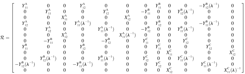 |
(A5) |
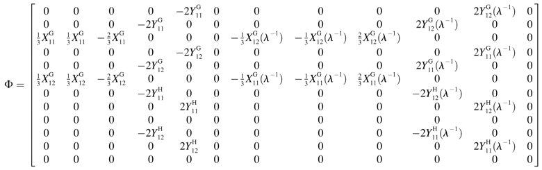 |
(A6) |
These scalar resistance functions can be readily computed for any given doublet based on their geometric parameters: the size of the larger sphere (a1), the ratio of the spheres radii (λ = a2/a1), and the dimensionless center-to-center distance, s (= 2(a2 + a1 + d)/(a2 + a1)) (see Eqs. 3.20, 3.21, 4.19, 4.20, 5.9, 5.10, 6.12, 6.13, 7.14, and 7.15 in Jeffrey and Onishi, 1984, and Eqs. 20, 28, and 36 in Jeffrey, 1992). It is evident that the relationship between s and the dimensionless separation distance δ(= d/a1) defined in Methods is given by s = 2 + 2δ/(1 + λ). Here the terms  and
and  represent dimensional quantities that are obtained from the corresponding dimensionless resistance functions using Eq. 1.7 in Jeffrey and Onishi (1984) and Eq. 3 in Jeffrey (1992). The terms
  and
and  refer to the evaluation of these functions at the specified s-value, using the reciprocal of the λ-value. Each of the 16 scalar coefficients is written in the form of a convergent series in powers of (1/s)m where m = 1,2,3, … . For results presented in the current article, these series were summed to m = 100. The coefficients thus determined were compared with the tables provided in Jeffrey (1992) and Jeffrey and Onishi (1984). For λ ≥ 0.01, the coefficients
  and
and  were within 0.5% of the tabulated values, whereas the rest of the coefficients were accurate to within 7%. In addition, the coefficients computed here were found to be within 3% of the tabulated values in Arp and Mason (1977) for equal-sized spheres with 0.0002 ≤ δ ≤ 18.
Expressions for strain and relative velocity-spin vector
In Eq. A4 the strain vector ℰ and relative velocity-spin vector 𝒰 are expressed in the particle-fixed coordinate system. ℰ is made up of the elements of the fluid rate-of-strain tensor. To compute  we first employ Eq. A1 to transform the velocity gradient tensor Gs from space-fixed coordinates to obtain the tensor G expressed in particle-fixed coordinates (Shankaran and Neelamegham, 2001a). This tensor is then split into the symmetric rate-of-strain tensor S = 1/2 (G + GT) and the vorticity tensor Λ = 1/2 (G − GT). The 1 × 12 ℰ vector is then expressed in terms of the components of S:
 |
(A7) |
The relative velocity-spin vector 𝒰 requires knowledge of two vectors for each of the particles, namely: 1), the vector describing the relative velocity between each of the spheres and the undisturbed fluid velocity at the sphere center (U − uf) and 2), the vector quantifying the relative angular velocity between the sphere and the fluid (Ω − ωf). Among these parameters, the fluid angular velocity is written as ωf = −1/2 ɛ: Λ where ɛ is the unit isotropic alternating triadic. Also, for a rigid dumbbell, Ω1 = Ω2 = ΩD, the angular velocity of the dumbbell.
Evaluation of U, uf, and ΩD requires an understanding of doublet motion in a linear shear field. 1), We define the center of free rotation CR of the doublet to lie at a distance a1ς from the origin O and along the doublet axis. For the case of equal spheres, CR coincides with O, i.e., ς = 0. As λ → 0, sphere 2 rotates about the center of sphere 1, i.e., ς → (1 + λ + δ)/2. If the linear fluid shear is expressed with respect to an origin placed at CR, the position vectors of the centers of spheres 1 and 2 with respect to CR are expressed as r1 = (0, 0, r/2–a1ς) and r2 = (0, 0, −r/2–a1ς), where r is the distance between the centers of spheres 1 and 2. The following results are then obtained: 1), the fluid velocity at the centers of spheres 1 and 2 is expressed as uf1 = r1 · G and uf2 = r2 · G and 2), the motion of the doublet composed of unequal spheres is described as the sum of a rigid-body rotation about CR with an angular velocity ΩD, and a drift velocity along the center-to-center line a1βS33 (Nir and Acrivos, 1973). Here, β is the axial drift velocity parameter. Both for the case of equal spheres and for λ → 0, CR is fixed in space with respect to a coordinate system moving with the fluid. Thus, the drift velocity in both cases is 0, i.e., β = 0. Also, the angular velocity of any solid body of revolution can be expressed in terms of the fluid rate-of-strain tensor and the fluid angular velocity vector as  (Bretherton, 1962), where νD is the angular velocity coefficient of the rigid dumbbell. Combining the above, the particle velocities are expressed as
  a1βS33] and
  a1βS33], where the superscripts (1) and (2) indicate the components of a vector along the particle-fixed axes X1 and X2, respectively. Overall, the 1 × 12 𝒰 vector can be written as
 |
(A8) |
Computation of force-torque vector
Substituting Eqs. A5–A8 into Eq. A3 results in expression of the various components of the forces and torques on the two spheres in terms of three unknown parameters: 1), the parameter ς, which describes the location of CR with respect to O; 2), the angular velocity coefficient, νD; and 3), the axial drift velocity parameter, β. These unknowns are determined by applying the condition of zero net force and torque on the dumbbell as detailed below.
 |
(A9a) |
 |
(A9b) |
 |
(A9c) |
Here, Eqs. A9a and A9c are statements of the fact that the net force along X1 and X3 are zero, whereas Eq. A9b sets the torque about CR in the direction of X2 to equal zero. Solution of Eqs. A9a and A9b together yield values of νD and ς, whereas Eq. A9c yields β. All three parameters are solely functions of λ and s. Values of νD, ς, and β computed here in the limit s → 2 compared well with values tabulated in Nir and Acrivos (1973) for the case of touching spheres. Also, the νD-values were found to match results provided in Arp and Mason (1977) for equal-sized spheres.
Once νD, ς, and β are obtained by solution of Eq. A9, these parameters are substituted back into Eq. A3 to obtain the values of hydrodynamic force and torques applied on the individual spheres for a given doublet orientation. To remain consistent with the notation of Tha and Goldsmith (1986), we express the solution of hydrodynamic forces applied on the spheres in the following form,
 |
(A10a) |
 |
(A10b) |
 |
(A10c) |
In the above equations α(i) are the force coefficients that are functions solely of the dumbbell geometry. Note that the force coefficients for  and
and  are equal. From the definition of the coordinate system, it is clear that the normal force (Fn) acts along the line joining the centers of the two spheres, and is given by
  (Eq. A11). The shear force (Fs) acts perpendicular to this direction and is expressed by the vector sum of
  and
and  (Eq. A12),
 |
(A11) |
 |
(A12) |
In the above expression, the coefficients αn and αs are solely functions of dumbbell geometric parameters, s and λ. αn is termed normal force coefficient and αs is called the shear force coefficient. The  term suggests that forces scale as a square of the particle size. The additional parameters in the equation capture the effects of shear rate, fluid viscosity, and doublet orientation on the applied normal and shear force. Values of hydrodynamic force coefficients computed in the limit s → 2 compared well with results presented in Nir and Acrivos (1973) for the case of touching spheres.
A2. Computation of period of rotation and dynamic force loading rate
The rotation of a rigid dumbbell about CR in a linear shear field is described by Eq. 3 in the manuscript text. In this equation,  is the equivalent spheroidal axis ratio of the rigid dumbbell, which is given by
  can be evaluated based on knowledge of νD which we computed in Appendix, section A1, above. The
  values computed here were in agreement with those tabulated in Adler (1981) for unequal spheres.
The dynamic force loading rate can be written as dF/dt = (∂F/∂φ1)(dφ1/dt) + (∂F/∂θ1)(dθ1/dt). It can be shown that both the maximum shear and normal force loading rates occur in the equatorial x2–x3 plane where θ1 = π/2 and dθ1/dt = 0. Combining Eqs. 3, A11, and A12, it can be shown that for a dumbbell rotating in the equatorial plane the force loading rates are given by
 |
(A13a) |
 |
(A13b) |
Analysis of Eqs. A13a and A13b reveals that the maximum normal and shear force loading rates can be written as
 |
where
 |
 |
(A13c) |
The maximum normal force loading rate is obtained when φ1 = nπ, and the maximum shear force loading rate is obtained when φ1 =  Thus, the orientation at which the maximum shear force loading rate occurs is a function of
  In Eq. A13c, κ(
 ) is a prefactor that varies from a value of 1 at
  to an asymptotic value of (3/4)√3 as → ∞.
A3. Application of Stokes law to calculate force applied on doublet when sphere 2 is much smaller than sphere 1
Detailed modeling of doublet kinematics (Appendix, section A1) results in an exact estimation of the magnitude of forces applied on the molecules. In addition, we demonstrate here that for a sufficiently small sphere 2, Stokes law can be applied to derive simple, albeit approximate, analytical expressions.
For this analysis, we consider the fact that a linear shear field constitutes the sum of two components: a purely rotational flow and an extensional flow. Whereas the rotational flow induces the tumbling motion of the cell/sphere/doublet, the extensional flow exerts both normal and shear forces on cell-surface molecules. Evaluation of the local flow in the vicinity of the larger sphere with radius a1 yields information that can be applied with Stokes law to estimate hydrodynamic forces.
For this analysis we first consider the disturbance in the local flow due to the presence of a sphere of radius a1 under purely extensional flow. In this case, the velocity at a distance r from the surface of a sphere of radius a1 can be expressed along the x1, x2, and x3 axes of the space-fixed coordinate system as in Batchelor (1967),
 |
(A14a) |
 |
(A14b) |
 |
(A14c) |
where M(r) = 1 −  /
/ and Q(r) = 5/2 (−
  The above expression is valid for a1 < r < ∞. We now wish to express the fluid velocity in spherical polar coordinates (r, θ1, and φ1), inasmuch as knowledge of fluid velocity in the r-direction can be readily used to evaluate normal forces, whereas the fluid velocity in the θ1 and φ1 are required for calculation of shear forces. Upon transformation of Eq. A14 into spherical coordinates, fluid velocity in the r, θ, and φ directions can be expressed as
 |
(A15a) |
 |
(A15b) |
 |
(A15c) |
We now model a cell-surface receptor bound to sphere 1 as a smaller sphere of radius a2 attached via a thin tether of length d such that a1ɛ = a2 + d. The center-to-center distance between spheres 1 and 2 thus equals r = a1(1 + ɛ). Substituting expressions for M(r) and Q(r) into Eq. A15 above, and applying Taylor series expansions (1 + ɛ)−2 ∼ 1 − 2ɛ + 3ɛ2 + O(ɛ3) and (1 + ɛ)−4 ∼ 1 − 4ɛ + 10ɛ2+O(ɛ3) for small ɛ, we get
 |
(A16a) |
 |
(A16b) |
 |
(A16c) |
Given the knowledge of ur, uθ, and uφ, upon application of Stokes law we can now estimate the force applied on this smaller sphere in the radial and tangential directions, i.e., Fr = 6πμa2 ur, Fθ = 6πμa2 uθ, and Fφ = 6πμa2 uφ. It is clear that the normal force Fn applied on the sphere equals Fr, whereas Fs = ( )1/2. This yields the following expressions for normal and shear force,
 |
(A17a) |
 |
(A17b) |
Using the trigonometric relations, sinθ1sinφ1 = sinθ2cosφ2, sinθ1cosφ1 = cosθ2, and cosθ1 = sinθ2sinφ2 (Arp and Mason, 1977), A17 reduces to Eq. 4 in Methods.
The analysis in this section thus far has neglected the disturbance/fluid velocity due to the presence of a finite-sized second sphere 2. When a2 ≪ a1, the current problem approaches that of a sphere near an infinite plane wall, which to order ɛ, is subjected to a linear shear flow with an orientation-dependent shear rate G* = 5/2G [sin2θ1(cos2θ1 sin22φ1 + cos22φ1)]1/2 (Eq. A16). Hydrodynamic forces that account for the disturbance velocity due to sphere 2 in such a scenario have been previously computed (Goldman et al., 1967). For the dimensions encountered in problems involving cell-surface receptors where the tether length d is sufficiently large compared to the globular domain size a2 (see Table 1), use of an asymptotic correction factor 1 + (9/16)[a2/(d + a2)] (Goldman et al., 1967) in the Stokes law equation yields a force value within 3% of that computed in Appendix, section A1 (results not shown).
Harish Shankaran's present address is Biological Sciences Division, Pacific Northwest National Laboratory, Richland, WA 99352.
References
- Adler, P. M. 1981. Interaction of unequal spheres. I. Hydrodynamic interaction: colloidal forces. J. Coll. Interf. Sci. 84:461–474. [Google Scholar]
- Alon, R., D. A. Hammer, and T. A. Springer. 1995. Lifetime of the P-selectin-carbohydrate bond and its response to tensile force in hydrodynamic flow. Nature. 374:539–542. [DOI] [PubMed] [Google Scholar]
- Arp, P. A., and S. G. Mason. 1977. The kinetics of flowing dispersions. VIII. Doublets of rigid spheres (theoretical). J. Coll. Interf. Sci. 61:21–43. [Google Scholar]
- Ballard, M. C. 1987. Atlas of Blood Cells in Health and Disease. United States Department of Health and Human Services, Atlanta, GA.
- Batchelor, G. K. 1967. An Introduction to Fluid Dynamics. Cambridge University Press, Cambridge.
- Becker, J. W., H. P. Erickson, S. Hoffman, B. A. Cunningham, and G. M. Edelman. 1989. Topology of cell adhesion molecules. Proc. Natl. Acad. Sci. USA. 86:1088–1092. [DOI] [PMC free article] [PubMed] [Google Scholar]
- Bird, R. B., C. F. Curtiss, R. C. Armstrong, and O. Hassager. 1987. Dynamics of Polymeric Liquids, Vol. 2, Kinetic Theory. John Wiley & Sons, New York.
- Brenner, H. 1974. Rheology of a dilute suspension of axisymmetric Brownian particles. Int. J. Multiphase Flow. 1:195–341. [Google Scholar]
- Brenner, H., and M. E. O'Neill. 1972. On the Stokes resistance of multiparticle systems in a linear shear field. Chem. Eng. Sci. 27:1421–1439. [Google Scholar]
- Bretherton, F. P. 1962. The motion of rigid particles in a shear flow at low Reynolds number. J. Fluid Mech. 14:284–304. [Google Scholar]
- Davies, P. F. 1995. Flow-mediated endothelial mechanotransduction. Physiol. Rev. 75:519–560. [DOI] [PMC free article] [PubMed] [Google Scholar]
- Drescher, B., E. Spiess, M. Schachner, and R. Probstmeier. 1996. Structural analysis of the murine cell adhesion molecule L1 by electron microscopy and computer-assisted modelling. Eur. J. Neurosci. 8:2467–2478. [DOI] [PubMed] [Google Scholar]
- Enderle, J. D., S. M. Blanchard, and J. D. Bronzino. 2000. Introduction to Biomedical Engineering. Academic Press, New York, NY.
- Erlandsen, S. L., S. R. Hasslen, and R. D. Nelson. 1993. Detection and spatial distribution of the β-2 integrin (Mac-1) and L-selectin (LECAM-1) adherence receptors on human neutrophils by high-resolution field emission SEM. J. Histochem. Cytochem. 41:327–333. [DOI] [PubMed] [Google Scholar]
- Fahrig, T., R. Probstmeier, E. Spiess, A. Meyer-Franke, F. Kirchhoff, B. Drescher, and M. Schachner. 1993. Functional topography of the myelin-associated glycoprotein. I. Mapping of domains by electron microscopy. Eur. J. Neurosci. 5:1118–1126. [DOI] [PubMed] [Google Scholar]
- Finger, E. B., K. D. Puri, R. Alon, M. B. Lawrence, U. H. von Andrian, and T. A. Springer. 1996. Adhesion through L-selectin requires a threshold hydrodynamic shear. Nature. 379:266–269. [DOI] [PubMed] [Google Scholar]
- Fowler, W. E., L. J. Fretto, K. K. Hamilton, H. P. Erickson, and P. A. McKee. 1985. Substructure of human von Willebrand factor. J. Clin. Invest. 76:1491–1500. [DOI] [PMC free article] [PubMed] [Google Scholar]
- Fox, J. E. B., L. P. Aggerbeck, and M. C. Berndt. 1988. Structure of the glycoprotein Ib-IX complex from platelet membranes. J. Biol. Chem. 263:4882–4890. [PubMed] [Google Scholar]
- Fung, Y. C. 1984. Biodynamics: Circulation. Springer-Verlag, New York.
- Goldman, A. J., R. G. Cox, and H. Brenner. 1967. Slow viscous motion of a sphere parallel to a plane wall-II couette flow. Chem. Eng. Sci. 22:653–660. [Google Scholar]
- Goldsmith, H. L., F. A. McIntosh, J. Shahin, and M. M. Frojmovic. 2000. Time and force dependence of the rupture of glycoprotein IIb-IIIa-fibrinogen bonds between latex spheres. Biophys. J. 78:1195–1206. [DOI] [PMC free article] [PubMed] [Google Scholar]
- Goldsmith, H. L., T. A. Quinn, G. Drury, C. Spanos, F. A. McIntosh, and S. I. Simon. 2001. Dynamics of neutrophil aggregation in couette flow revealed by videomicroscopy: effect of shear rate on two-body collision efficiency and doublet lifetime. Biophys. J. 81:2020–2034. [DOI] [PMC free article] [PubMed] [Google Scholar]
- Jeffery, G. B. 1922. The motion of ellipsoidal particles immersed in a viscous fluid. Proc. Roy. Soc. A102:161–179. [Google Scholar]
- Jeffrey, D. J. 1992. The calculation of the low Reynolds number resistance functions for two unequal spheres. Phys. Fluids A. 4:16–29. [Google Scholar]
- Jeffrey, D. J., and Y. Onishi. 1984. Calculation of the resistance and mobility functions for two unequal rigid spheres in low-Reynolds-number flow. J. Fluid Mech. 139:261–290. [Google Scholar]
- Kroll, M. H., J. D. Hellums, L. V. McIntire, A. L. Schafer, and J. L. Moake. 1996. Platelets and shear stress. Blood. 88:1525–1541. [PubMed] [Google Scholar]
- Merkel, R., P. Nassoy, A. Leung, K. Ritchie, and E. Evans. 1999. Energy landscapes of receptor-ligand bonds explored with dynamic force spectroscopy. Nature. 397:50–53. [DOI] [PubMed] [Google Scholar]
- Nir, A., and A. Acrivos. 1973. On the creeping motion of two arbitrary-sized touching spheres in a linear shear field. J. Fluid Mech. 59:209–223. [Google Scholar]
- Nollert, M. U., N. J. Panaro, and L. V. McIntire. 1992. Regulation of genetic expression in shear stress-stimulated endothelial cells. Ann. N. Y. Acad. Sci. 665:94–104. [DOI] [PubMed] [Google Scholar]
- Ottinger, H. C. 1996. Stochastic Processes in Polymeric Fluids. Springer-Verlag, Berlin, Germany.
- Patel, K. D., M. U. Nollert, and R. P. McEver. 1995. P-selectin must extend a sufficient length from the plasma membrane to mediate rolling of neutrophils. J. Cell Biol. 131:1893–1902. [DOI] [PMC free article] [PubMed] [Google Scholar]
- Shankaran, H., P. Alexandridis, and S. Neelamegham. 2003. Aspects of hydrodynamic shear regulating shear-induced platelet activation and self-association of von Willebrand factor in suspension. Blood. 101:2637–2645. [DOI] [PubMed] [Google Scholar]
- Shankaran, H., and S. Neelamegham. 2001a. Effect of secondary flow on biological experiments in the cone-plate viscometer: methods for estimating collision frequency, wall shear stress and inter-particle interactions in non-linear flow. Biorheology. 38:275–304. [PubMed] [Google Scholar]
- Shankaran, H., and S. Neelamegham. 2001b. Nonlinear flow affects hydrodynamic forces and neutrophil adhesion rates in cone-plate viscometers. Biophys. J. 80:2631–2648. [DOI] [PMC free article] [PubMed] [Google Scholar]
- Smith, M. J., E. L. Berg, and M. B. Lawrence. 1999. A direct comparison of selectin-mediated transient, adhesive events using high temporal resolution. Biophys. J. 77:3371–3383. [DOI] [PMC free article] [PubMed] [Google Scholar]
- Taylor, A. D., S. Neelamegham, J. D. Hellums, C. W. Smith, and S. I. Simon. 1996. Molecular dynamics of the transition from L-selectin- to β2-integrin-dependent neutrophil adhesion under defined hydrodynamic shear. Biophys. J. 71:3488–3500. [DOI] [PMC free article] [PubMed] [Google Scholar]
- Tees, D. F., O. Coenen, and H. L. Goldsmith. 1993. Interaction forces between red cells agglutinated by antibody. IV. Time and force dependence of breakup. Biophys. J. 65:1318–1334. [DOI] [PMC free article] [PubMed] [Google Scholar]
- Tha, S. P., and H. L. Goldsmith. 1986. Interaction forces between red cells agglutinated by antibody. I. Theoretical. Biophys. J. 50:1109–1116. [DOI] [PMC free article] [PubMed] [Google Scholar]
- Uff, S., J. M. Clemetson, T. Harrison, K. J. Clemetson, and J. Emsley. 2002. Crystal structure of the platelet glycoprotein Ibα N-terminal domain reveals an unmasking mechanism for receptor activation. J. Biol. Chem. 277:35657–35663. [DOI] [PubMed] [Google Scholar]
- Ushiyama, S., T. M. Laue, K. L. Moore, H. P. Erickson, and R. P. McEver. 1993. Structural and functional characterization of monomeric soluble P-selectin and comparison with membrane P-selectin. J. Biol. Chem. 268:15229–15237. [PubMed] [Google Scholar]
- van de Ven, T. G. M., and S. G. Mason. 1976. The microrheology of colloidal dispersions. V. Primary and secondary doublets of spheres in shear flow. J. Coll. Interf. Sci. 57:517–534. [Google Scholar]
- van den Berg, B. M., H. Vink, and J. A. Spaan. 2003. The endothelial glycocalyx protects against myocardial edema. Circ. Res. 92:592–594. [DOI] [PubMed] [Google Scholar]
- White, J. G. 1984. The ultrastructure and regulatory mechanisms of blood platelets. In Blood Platelet Function and Medicinal Chemistry. A. Lasslo, editor. Elsevier Biomedical, New York, NY.