

Abstract
In molecular dynamics simulations of lipid bilayers, the structure is sensitive to the precise treatment of electrostatics. The dipole-dipole interactions between headgroup dipoles are not long-ranged, but the area per lipid and, through it, other properties of the bilayer are very sensitive to the detailed balance between the perpendicular and in-plane components of the headgroup dipoles. This is affected by the detailed properties of the cutoff scheme or if long-range interactions are included by Ewald or particle-mesh Ewald techniques. Interaction between the in-plane components of the headgroup dipoles is attractive and decays as the inverse sixth power of distance. The interaction is screened by the square of a dielectric permittivity close to the value for water. Interaction between the components perpendicular to the membrane plane is repulsive and decays as the inverse third power of distance. These interactions are screened by a dielectric permittivity of the order 10. Thus, despite the perpendicular components being much smaller in magnitude than the in-plane components, they will dominate the interaction energies at large distances.
INTRODUCTION
Lipid bilayers play an important role in biological cells, both as barriers to maintain concentrations and as matrices to support membrane proteins. They have been subject to extensive experimental research, and are fairly well characterized in terms of structural as well as dynamical properties. See e.g., Bloom et al. (1991) and Nagle and Tristram-Nagle (2000).
Computer simulations at an atomic level (molecular dynamics and Monte Carlo) of lipids bilayers act as a complement to experiments. The development in computer hardware during the last decades has allowed the models to successively become more detailed and the systems simulated to expand significantly both in size (i.e., number of atoms) and in simulation time (Pastor, 1994; Tieleman et al., 1997; Feller, 2000; Saiz and Klein, 2002; Scott, 2002). These circumstances both allow and call for proper evaluation of models and methodology.
The properties of lipid bilayers in the high-temperature liquid crystalline (Lα) phase are sensitive to details. This is seen from experimentally observed differences between lipid bilayers composed of slightly different lipids. For instance, phosphatidyl cholines and ethanol amines differ in area per lipid by 10–20% (depending on lipid chain length; Balgavý et al., 2001; Nagle and Tristram-Nagle, 2000; Petrache et al., 2000). This means that the replacement of the three methyl groups in choline by hydrogens reduces the area per lipid considerably. In computer simulations, differences in setup may have large effects on the properties of the bilayer. These differences include changes in the Lennard-Jones parameters for the hydrocarbon chains (Berger et al., 1997; Anézo et al., 2003), inclusion of long-range electrostatics by means of Ewald summation, particle-mesh Ewald (PME), or reaction-field methods instead of using different cutoff schemes (Venable et. al., 2000; Tobias, 2001; Pandit and Berkowitz, 2002; Patra et al., 2003; Anézo et al., 2003) and system sizes (Lindahl and Edholm, 2000a). Finite size effects have also been suggested and discussed by Feller and Pastor (1996, 1999), and Feller et al. (1997). Even changes in the cutoff distance for the short-ranged Lennard-Jones interaction seem to have non-negligible effects (Patra et al., 2003; Anézo et al., 2003).
There are several ways of measuring the order in lipid bilayers. NMR-order parameters, chain disorder as measured by the amount of gauche bonds, area per lipid, or bilayer thickness are examples. Even if these parameters reflect different properties of the system, there is a strong correlation between them, and one may therefore, in a first analysis, concentrate on one of them. The one that most easily helps in understanding the physical properties of the bilayers is perhaps the area per lipid. The thickness of the bilayer is immediately related to the area since the volume is approximately constant. NMR-order parameters and the fraction of gauche bonds are also obtained therefrom, since small areas order the lipids whereas a large area disorders them. Given that the system is free to adjust its area per lipid to attain surface tension zero, differences in area per lipid between different systems and between different simulation setups may be viewed as consequences of interactions giving rise to different contributions to the surface tension. One way of analyzing this, in terms of entropy/energy and spatial resolution of different interactions, was suggested by Lindahl and Edholm (2000b). Here we will do the analysis in a different way, based on simulations as well as on analytic expressions for long-range electrostatics. The purpose is to shed light on the reason for the differences between different simulation setups.
To do this, it is important to realize that the surface tension can be written as a difference between normal (PN) and lateral pressures (PL),
 |
(1) |
where z is the normal direction and the integration is performed over the entire bilayer. This means that changes in strength or cutoff of interactions have no effect unless they are anisotropic—i.e., have a different effect in the normal and lateral components of the pressure. Usually, this effect is not due to an explicit orientation dependence of the forces but to the molecules being anisotropic, and ordered according to this anisotropy. Coulomb and Lennard-Jones potentials are spherically symmetric. Still, changes in their strength or cutoffs may, due to the spatial and orientational ordering of the molecules, induce different effects upon the lateral and normal pressures, and thereby give rise to a changed surface tension and thus, in the end, change the surface area.
It is further important to realize that it is much easier to induce changes in the area that are coupled to thickness changes, and therefore occur at constant volume, rather than to induce volume changes. The volume compressibility of lipid bilayers is ∼0.5 × 10⁻⁴ atm−1 (Braganza and Worcester, 1986) which is of the same order of magnitude as that of liquid hydrocarbons (1 × 10⁻⁴ atm−1, value for pentadecane from Weast, 1977–1978). This means that a change of the pressure by 1 atm induces a relative volume change of 0.5 × 10⁻⁴. In contrast to this, the area compressibility modulus for lipid bilayers is of the order KA = 250 mN/m (Nagle and Tristram-Nagle, 2000). The change in area, ΔA, induced by a change in surface tension, Δγ, is then obtained as
 |
(2) |
This means that a change of the difference between the normal and lateral pressure with 1 atm over a 4-nm-thick bilayer will induce a relative area change of 1.6 × 10⁻³. Thus, the area is 30 times more sensitive to pressure changes than the volume. The reason for this is that the systems change shape much more easily than density.
We will here present a series of simulations of hydrated Lα phase dipalmitoyl phosphatidylcholine (DPPC) bilayers in which we vary a number of properties and parameters. They include the cutoff methods, system sizes, and hydration. Further, we will use PME simulations of a large lipid bilayer to calculate the distance dependence of the electrostatic interactions in the headgroup region and make contact with simplified theories for the long-range interactions.
We will show that the differences in the results obtained from cutoff and PME simulations can only partially be explained by the inclusion of long-range electrostatic interactions. More important is the fact that cutoff simulations are more sensitive than PME simulations to the overall setup, and that they rely heavily on how the cutoff scheme is constructed.
COMPUTATIONAL DETAILS
All simulations were performed using the parallel version of the GROMACS package (Berendsen et al., 1995; Lindahl et al., 2001; GROMACS, 2001) on a small cluster of dual-Pentium machines running Linux. All systems were subject to periodic boundary conditions in all directions. The temperature was kept constant at 323 K using a Berendsen thermostat (Berendsen et al., 1984) with coupling time constant 0.1 ps for water and lipids separately. The pressure was coupled to three Berendsen barostats of 1 atm separately in the three space coordinates, using a time constant of 5.0 ps. Although more modern thermostats and barostats, with better properties (Parrinello and Rahman, 1981; Nosé, 1984; Hoover, 1985; Allen and Tildesley, 1987), are available in the GROMACS package, we opted for the same setup as in previous investigations (Berger et al., 1997; Lindahl and Edholm, 2000a; Patra et al., 2003) to minimize the differences with respect to their simulations.
The integration was performed using the leap frog algorithm with a time step of 4 fs. A cutoff of 1.0 nm was used for the Lennard-Jones (LJ) interactions. The electrostatic interactions were calculated using either a group based, twin-range cutoff of 1.0 and 1.8 nm, with the long-range forces updated every 10th step, or the particle-mesh Ewald (PME) method (Darden et al., 1993; Essmann et al., 1995) outside a cutoff of 1.0 nm. The force field used is built on GROMOS parameters for the bonded interactions (van Gunsteren et al., 1996). The charges for the DPPC headgroups were taken from ab initio calculations by Chiu et al. (1995). In the cutoff simulations different charge group schemes were used as described and discussed in Results, below. OPLS LJ parameters (Jorgensen and Tirado-Rives, 1988) were used for the lipid headgroups. The united atom CH2/CH3 parameters for the hydrocarbon chains were those of Berger et al. (1997). All electrostatic 1–4 interactions were reduced by a factor 2, with the LJ 1–4 interaction reduced by a factor 8, according to the OPLS scheme. For the hydrocarbon chains, Ryckaert-Bellemans dihedrals (Ryckaert and Bellemans, 1975) were used, implying exclusion of the 1–4 LJ interactions. Bonds were kept constant using the LINCS algorithm (Hess et al., 1997). For the water we used the SPC model (Berendsen et al., 1981), bonds and angles held constant using the analytical SETTLE method (Miyamoto and Kollman, 1992). The setup used in this work has been reported to produce results in good agreement with experimental data (Berger et al., 1997; Lindahl and Edholm, 2000a). When it comes to system size, this work is based upon a large number of simulations using different setups for the number of lipids (64, 128, 256, or 1024) as well as the number of water molecules per lipid (15, 23, 28.5, or 35). The simulation times varies between 5 ns for the largest system up to 30 ns for the smallest one.
RESULTS FROM THE SIMULATIONS
The effects of using different charge groups
GROMACS and most other molecular dynamics programs use a charge group method for handling cutoffs. The reason for this is that most molecules, although they have zero net charge, have a distribution of charges which gives rise to dipole-dipole and higher multipole interactions at long distances. This is represented by fractional charges distributed on the atoms. Usually, nearby atoms are grouped together into groups of zero net charge, and electrostatic interactions are calculated as Coulomb interactions between these charges. Applying a simple cutoff would lead to a situation where some of the atoms in one group would interact only with some of the atoms of another group. This would give strong interactions of Coulomb type close to the cutoff, clearly an artifact of the cutoff itself. Therefore, one usually uses a group-based cutoff where either all or none of the interactions between the atoms in two charge groups are included. This works well when the charge groups are small but may lead to incorrect results when charge groups are large and nonspherical. This is indeed the problem with phospholipids which are neutral but have a huge dipole moment that may be represented by two unit charges of opposite sign ∼0.5-nm apart. One then has the choice either to work with neutral charge groups and accept the artifacts that the nonspherical cutoff will cause, or to find a suitable compromise with non-neutral charge groups. As noted by Patra et al. (2003), this can give rise to artifacts close to the cutoff in the pair correlation functions. Some early trials were done to investigate the effects of different schemes for handling the cutoffs (e.g., Berger et al., 1997); but in retrospect we can conclude that the simulations at that time were too short to see differences.
Here, we have performed cutoff simulations using four different constructions for the charge groups. These simulations include 128 lipids and 28.5 waters per lipid, and were run for 20 ns, of which the last 10 were used for analysis. The cutoff schemes are illustrated in Fig. 1.
FIGURE 1.

The definition of the charge groups investigated (shaded areas) and their net charges.
The charge groups used were the non-neutral groups of Lindahl and Edholm (2000a), labeled I; those of Tieleman and Berendsen (1996), Patra et al. (2003), and Berger et al. (1997), labeled II—similar to type I, but uses one group less for the P-N dipole, also non-neutral; the neutral groups of Chiu et al. (1995) and Berger et al. (1997), labeled III—uses the P-N dipole as one group as whole; and finally a setup without charge groups, labeled IV. It should be noted that even if charge groups have been used in most cutoff simulations, this fact and the exact construction of these groups have not always been mentioned in the publications. The unphysical peak in the pair correlation functions at the cutoff (1.8 nm) that was demonstrated by Patra et al. (2003) for case II is clearly seen in our corresponding Fig. 2 for cases I, II, and IV. It is largest for case IV (no charge groups). In the simulation with neutral charge groups, III, the peak is absent and the pair correlation function quite similar to the one from the PME simulations.
FIGURE 2.

Pair correlation function between the headgroup phosphorus atoms from simulations with different charge groups, type I–IV (from Fig. 1, simulations 9, 13, 14, and 15, solid lines). The pair correlation from a PME simulation (simulation 10, dotted) is added in for comparison in all figures. The functions are displayed as running averages over 0.1 nm.
The simulations were run at constant pressure of 1 atm in all coordinate directions. The resulting areas per lipid from the four simulations are shown in Table 1, simulations 9, 13–15, and in Fig. 3, together with the area from a PME simulation.
TABLE 1.
The different simulations referred to in this article
| ID | Nl | nw/l | c.g. | Time | A/l | 〈p〉 | 〈pxy〉 | 〈pz〉 | 〈α〉 |
|---|---|---|---|---|---|---|---|---|---|
| 1 | 1024 | 23 | I | 10 (5) | 0.633 (0.002) | 0.523 | 0.431 | 0.131 | 75° |
| 2 | 1024 | 23 | PME | 5 (4) | 0.634 (0.002) | 0.505 | 0.398 | 0.145 | 72° |
| 3 | 256 | 23 | PME | 20 (10) | 0.632 (0.003) | 0.501 | 0.390 | 0.138 | 73° |
| 4 | 64 | 23 | PME | 30 (20) | 0.627 (0.009) | 0.509 | 0.393 | 0.136 | 73° |
| 5 | 128 | 15 | I | 20 (15) | 0.619 (0.005) | 0.518 | 0.429 | 0.116 | 76° |
| 6 | 128 | 15 | PME | 20 (15) | 0.626 (0.008) | 0.502 | 0.395 | 0.144 | 72° |
| 7 | 128 | 23 | I | 20 (15) | 0.612 (0.007) | 0.519 | 0.432 | 0.129 | 75° |
| 8 | 128 | 23 | PME | 20 (15) | 0.631 (0.008) | 0.504 | 0.395 | 0.150 | 71° |
| 9 | 128 | 28.5 | I | 20 (15) | 0.603 (0.006) | 0.526 | 0.444 | 0.138 | 74° |
| 10 | 128 | 28.5 | PME | 20 (15) | 0.640 (0.007) | 0.506 | 0.402 | 0.146 | 72° |
| 11 | 128 | 35 | I | 20 (15) | 0.584 (0.005) | 0.518 | 0.433 | 0.131 | 75° |
| 12 | 128 | 35 | PME | 20 (15) | 0.626 (0.009) | 0.503 | 0.392 | 0.149 | 71° |
| 13 | 128 | 28.5 | II | 20 (15) | 0.552 (0.003) | 0.514 | 0.443 | 0.117 | 77° |
| 14 | 128 | 28.5 | III | 20 (10) | 0.537 (0.004) | 0.537 | 0.461 | 0.112 | 78° |
| 15 | 128 | 28.5 | IV | 10 (9) | 0.611 (0.006) | 0.512 | 0.399 | 0.162 | 70° |
The columns are: ID, Simulation ID (for references within this article); Nl, number of lipids used in the simulation; nw/l, number of water per lipid; c.g., type of charge-group construction (from the definitions in Fig. 1); Time, total simulation time and time used for analysis (in ns); A/l, area per lipid; and the last four columns, RMSD of 10 subsets of the trajectory in nm2, the magnitude of different components of the headgroup dipole in e times nm, and the tilt angle with respect to the membrane normal in degrees.
FIGURE 3.

Area per lipid versus simulation time for the different charge group constructions investigated, compared to a PME simulation. Data is taken from simulations 9, 10, 13, 14, and 15.
Interestingly enough, there seems to be a correspondence between the area per lipid and the number of charge groups used for the P-N dipole. Charge groups of type I use three groups for the P-N dipole and the simulated area is 0.604 nm2. Charge groups of type II which use two groups for the P-N dipole give a smaller area, 0.553 nm2. Neutral charge groups give an even smaller area, 0.537 nm2, and finally, type IV charge groups, which can be interpreted as one charge group per atom, give the largest area, 0.611 nm2.
Neutral charge groups eliminate the peak in the correlation functions at the cutoff and are in that respect most similar to the PME simulation. The area per lipid from that simulation is, however, the one that differs most from the PME simulation, and from experiments. This indicates that large charge groups and a nonspherical cutoff cause large artifacts. Clearly the absence of a peak in the pair correlation function is not a good single criterion that the cutoff is taken properly. For further comparison between PME and cutoff simulations we have chosen to use cutoff scheme I because it gives a reasonable, although significantly too small, area and still has the smallest peak in the pair correlation function at the cutoff. We also note that Lindahl and Edholm (2000a) demonstrated a considerable finite size effect that, when corrected for, brought the area of a large system using that particular cutoff scheme (at a slightly lower hydration) up to ∼0.635 nm2, in agreement with the experimental figure.
Another property of the electrostatic interactions that influences the area is the treatment of short-range electrostatics between atoms separated by three bonds (1–4 interactions). As mentioned earlier, the OPLS united atom force field reduces these interactions by a factor 2. This seemingly somewhat arbitrary recipe has not been followed in all simulations. Short trial simulations indicated that omission of this scaling makes headgroups less flexible and may increase the area per lipid by as much as 5%.
Finite size effects
The size of the system (number of lipids) clearly affects the simulated area per lipid. In Lindahl and Edholm (2000a) it was shown that there is an almost linear dependence between the area per lipid and the inverse of the number of lipids in cutoff simulations. This is indeed the case also when using PME but the slope is considerably smaller than in the cutoff simulations shown in Fig. 4. Thus, the difference in area between cutoff and PME gets smaller in larger systems, and eventually vanishes completely.
FIGURE 4.

Area per lipid versus inverse system size for simulations with PME (triangles, simulations 2, 3, 4, and 8) and with 1.8-nm cutoff (circles, from Lindahl and Edholm, 2000a) for the electrostatics. The hydration was 23 waters per lipid in all simulations. In the cutoff simulations the charge groups were chosen as in Lindahl and Edholm (2000a), labeled I in present article.
The effects of different hydration
The experimental area per lipid is usually given in the biologically relevant state of full hydration. Lower hydration may affect both experimental areas and areas from simulations. The number of water molecules needed per DPPC lipid in the high temperature phase to obtain full hydration is generally believed to be 20–30. Many early simulations tended to keep this number on the low side to not unnecessarily increase system size and computer time. With present programs and computer speeds this may, however, be explored more systematically. We have, therefore, performed simulations at four different levels of hydration; 15, 23, 28.5, and 35 waters per lipid, using both a cutoff of 1.8 nm and PME.
It should be noted here that our intention is not to test whether our force field is able to handle systems at very low hydration, which indeed would be an important task. Our aim is rather to find out whether or not the properties of the bilayer is affected in the range usually considered as being full hydration. One would expect that all properties of the lipid bilayer, including area per lipid, eventually level off with increasing hydration. As seen in Fig. 5, the area per lipid seems to be independent of water content in the interval 15–35 waters per lipid in the PME simulations. In the cutoff simulations we note that the area decreases with increasing water content. This is qualitatively consistent with the pressure curve in Lindahl and Edholm (2000b), which shows a positive lateral pressure of almost 200 bar in the center of the water region in a small 64-lipid system with 23 waters per lipid. In that simulation the computed area per lipid is somewhat on the small side, which was taken as an indication that another 4–5 waters per lipid should be added to obtain full hydration. This would decrease the surface tension by ∼5 mN/m. To attain zero surface tension one would then need to increase the area per lipid by ∼0.01 nm2. Still, it is a bit worrying that the area per lipid does not level off with increasing water content for the cutoff simulations. We also note that the increase in area upon going from 23 to 15 waters per lipid—where one would expect that the effect of dehydration would give the opposite result (e.g., McIntosh, 2000)—is too small to be significant which is evident from the error bars.
FIGURE 5.

Area per lipid versus hydration for simulations with PME (triangles) and with 1.8 nm cutoff (circles) for the electrostatics (simulations 5–12). In the cutoff simulations the charge groups were chosen as in Lindahl and Edholm (2000a), labeled I in present article.
The fact that PME simulation seems less sensitive to the hydration means that the difference in area between cutoff and PME simulations will be larger at higher levels of hydration.
LENNARD-JONES INTERACTIONS
It has been shown that the usual parameters for hydrocarbon groups used in many force fields developed for protein simulations are inappropriate for longer hydrocarbon chains like those in lipids (Berger et al., 1997; Chiu et al., 1999). A fit of the Lennard-Jones parameters to obtain the correct density and heat of vaporization for liquid pentadecane resulted in a reduction of the depth of the well in the Lennard-Jones potential from values of 0.5 or even 0.585 kJ/mol down to 0.38 kJ/mol. Unfortunately, experimental values for the heat of vaporization for liquid hydrocarbons obtained by different methods differ considerably. The usage of more recent and reliable values obtained by calorimetric methods (Lide, 1999–2000; Majer and Svoboda, 1985), as opposed to using Clapeyron's equation with extrapolated vapor pressure data (Weast, 1977–1978), results in the value 0.42 kJ/mol (Wohlert, 2001; Chiu et al., 2003). This means that the difference in strength of Lennard-Jones interactions between short and long lipid hydrocarbon chains is smaller than suggested by Berger et al. (1997) but still important. It is clear that these parameters affect the area per lipid quite sensitively. Trial simulations show that an increased strength of the Lennard-Jones interactions by 10% reduces the area by 5%.
Also long-range Lennard-Jones interactions may affect the area per lipid. Patra et al. (2003) showed that an increased cutoff for the Lennard-Jones interactions from commonly used values, 1 nm up to 1.4 nm, results in a 3–10% smaller area. An analytical correction due to the finite cutoff can be calculated if we assume a pair correlation function equal to unity outside the cutoff. Inclusion of such a dispersion correction will also decrease the area, according to Lagüe et al. (2004). The effect noted in their work is, however, much smaller than in the works previously mentioned. They calculated a correction to the surface tension due to dispersion interactions of 0.8 mN/m, outside a cutoff of 1.0 nm. This would, from Eq. 2, correspond to a decrease in the area of <0.5%. From a 5-ns simulation using dispersion correction of a system containing 128 lipids, we observe a decrease in area by a few percent. We conclude that our simulation is too short to make any quantitative statements regarding this effect.
The anisotropic effect of changing the Lennard-Jones interactions, which in themselves are isotropic, has to do with the lipid chains not being randomly oriented, but tending to be normally oriented to the membrane. Increased attraction between the hydrocarbon groups will then be more effective in bringing different chains closer to each other, than in shortening the chains by intrachain Lennard-Jones interactions.
The Lennard-Jones interactions also have a minor effect on the volume density. Inclusion of a dispersion correction will not only decrease the area, but Berger et al. (1997) has shown that it leads to an increase in volume density of 2.9%. This is consistent with direct simulations reported by Patra et al. (2003).
The electrostatics
In the simulations, electrostatic interactions are taken into account as Coulomb interactions between fractional charges that are shielded by explicit molecular water. To get a better physical understanding, we will try to map the simulations upon a model consisting of layers of interacting point dipoles that are shielded in a continuum electrostatic model. The dipoles will then have one component in the membrane plane (xy component), and one perpendicular z component, both of which will be treated as fixed in size. Furthermore, the layers will be considered as perfect planes, i.e., we will neglect the effect from undulations upon the dipole-dipole interactions. All these assumptions will then be tested against data from the simulations which will be used to determine dielectric permittivities of the interface region and the relative sizes of the two components of the dipoles.
For this purpose, we first give the relevant equations from electrostatics and statistical mechanics. The equation for the electrostatic interaction energy between dipoles 1 and 2 reads
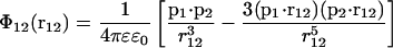 |
(3) |
in SI units, with ɛ0 being the electric permittivity of vacuum, ɛ the relative dielectric permittivity, p1 the dipole moment vector, and r12 the vector connecting dipole 1 and dipole 2.
The surface tension, γ, is in statistical mechanics defined as
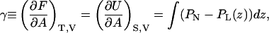 |
(4) |
with F being the free energy, A the area, T the temperature, V the volume, U the internal energy, S the entropy, PN the normal (z), and PL the lateral (xy) pressure component. The surface tension is usually calculated from the virial theorem, which gives the above equation in a more detailed form; but for the purpose of understanding the electrostatic contributions to the surface tension, we will make a simplified mean field model for these interactions. In such a model, no entropy will appear and we may as well take the derivative of the average energy with respect to area at constant temperature.
Before doing the actual calculations, we need to comment on the parameters in this equation. The headgroup dipoles of lipids are huge. Two full electron charges at a distance of ∼0.5 nm give a dipole moment of 8 × 10⁻²⁹ Cm or 24 Debye which corresponds to ∼10 times the dipole moment of a water molecule. A tilt angle of ∼70° with respect to the membrane normal leaves a component of ∼25% that points perpendicular to the membrane. This perpendicular component will then be approximately seven Debye or approximately three times the size of a water dipole, whereas the in-plane component is an order-of-magnitude larger than a water dipole. The relative dielectric constants are ɛw = 80 in the water, ɛl = 2–4 in the interior of the membrane, and ɛh in the lipid-water interface. The value for ɛl is the experimental value. However, in the simulations no charges exist in the interior of the membrane, thus the appropriate value in the hydrocarbon region is truly one. On the other hand, the dipoles lie in sheets which are not infinitesimally thin, surrounded by explicit water molecules. This means that there will be an effective shielding of the interactions between dipoles in different layers which may be represented by a relative dielectric permittivity different from unity. The value of ɛh is not known experimentally as far as we know, but Stern and Feller (2003) has calculated it from the fluctuations of dipoles in a molecular dynamics simulation. Their result was that ɛh is anisotropic with a large difference between the components parallel to the membrane plane (ɛ‖) and the perpendicular component (ɛ⊥). We will calculate ɛh in a different way.
The electrostatic interactions will consist of interactions between dipoles in the same sheet (monolayer) and interactions between different monolayers. In each case there will be three contributions; between perpendicular components, between in-plane components, and between perpendicular and in-plane components. For the interactions inside one planar sheet the last term will be zero.
Interaction between the perpendicular components within one layer
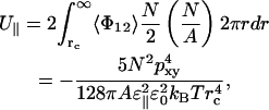
Within a layer, the interaction energy between the perpendicular components of two dipoles at distance r will be
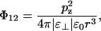 |
(5) |
where we have denoted the relative dielectric permittivity in the headgroup region ɛ⊥, since the perpendicular components of the dipoles interact via electric fields that point perpendicular to the bilayer.
The total energy in a bilayer outside the cutoff radius (rc) is then twice the integral over the monolayer,
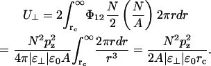 |
(6) |
This gives a negative contribution to the surface tension,
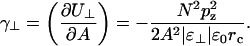 |
(7) |
This depends on the relative dielectric permittivity of the headgroup region. One may calculate an average permittivity of the headgroup region in different ways. One way is to integrate the Poisson equation in planar symmetry twice across the monolayer surface to get the total change in electrostatic potential passing across the dipole monolayer,
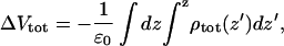 |
(8) |
from the total charge density including lipids as well as water. The values for ΔVtot varies between the simulations, but they are negative and typically 500–850 mV (see Fig. 6). Here the negative sign means that the electrostatic potential is lower in the water solution than inside the membrane. The resulting sign is consistent with experiment whereas the magnitude of the dipole potential is on the high side. Experiments give dipole potentials ∼−280 V (Brockman, 1994) with quite big uncertainties and differences between different systems and measurement techniques. There exists some evidence that the dipole potential should decrease when using Ewald summation instead of cutoffs for the electrostatics. Feller et al. (1996) obtained a dipole potential of >2 V using a cutoff for the electrostatics of 1.2 nm. However, simulations using longer cutoffs seem to give potentials in the same range as we observe for Chiu et al. (1995) and Patra et al. (2003). As for the difference between PME and cutoffs, taking into account an estimated statistical error of ±200 mV, we cannot observe any statistically significant trends in our results.
FIGURE 6.

Electrostatic potential across one monolayer as function of the z coordinate from a cutoff simulation (9, dashed) and a PME simulation (10, solid). The potential is set to zero in the interior of the membrane for reference. The relative dielectric permittivity is calculated from ɛ⊥ = ΔVlip/ΔVtot.
One may also calculate the electrostatic potential due to the charge distribution from the lipids only, ρlip(z). This is
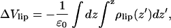 |
(9) |
and becomes ∼+5 V from the simulations. A continuum electrostatic model now says that
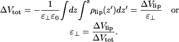 |
(10) |
This means that the electrostatic field from polarized water dominates over the field from the lipid dipoles and gives a negative ɛ⊥ in the range −5 to −11. This overpolarization is consistent with other simulations and necessary to explain the experimental dipole potential if the net lipid dipole is oriented with its positive end toward the water.
We now get at a numerical value for this contribution to the surface tension from Eq. 7, γ⊥ ≈ −7 mN/m outside a cutoff of 1.8 nm. This leads to an increase in area, from Eq. 2, of ∼0.017 nm2 per lipid. For a 1.2-nm cutoff this value would increase to ∼0.03 nm2.
Interaction between the components in the bilayer plane in the same layer
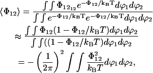
The interaction energy of two dipoles in the same layer forming the angles ϕ1 and ϕ2, respectively, with the joining vector of length r, is
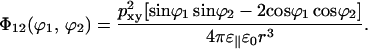 |
(11) |
With all orientations equally probable, this will average to zero. If we average over a Boltzmann distribution there will, however, be an average attraction. With a relative dielectric permittivity of 10, typical interaction energies will be of the order 0.2 kBT at the cutoff distance. Therefore we may do a series expansion of the exponential and put exp(−Φ12/kBT) = 1−Φ12/kBT. This gives the average interaction energy between two dipoles separated by a distance r,
 |
(12) |
which becomes
 |
(13) |
where the correlation function g(r) describes how the dipoles lose orientational correlation with distance
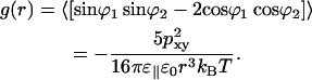 |
(14) |
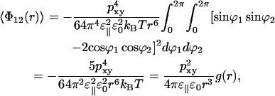
This energy can be recalculated as a function of r from stored simulation coordinates. Each lipid is then replaced by a single dipole and the water is omitted. Eq. 13 contains the dielectric permittivity squared. One of the ɛ‖ take the direct shielding from the water into account, and the other ɛ‖ comes from the correlation function. The later ɛ‖ will be seen in the data reconstructed from the simulation but not the former. As seen from Fig. 7, the data can be fitted to a r−6 function. From the constant in front of this ɛ‖ can be determined to 80 (±20), e.g., approximately the same as for water. The accuracy is limited by noise at large distances where the energy is very small and by that the approximations behind Eq. 13 become less good at small distances.
FIGURE 7.

The calculated interaction energy of the in-plane components of the headgroup dipoles, −〈Φ12(r)〉, from simulation 2, as a function of interaction distance displayed as a running average over 0.3 nm, compared to the mean field result from Eq. 13 (straight lines) for different values of the relative dielectric permittivity; 40 (dotted), 80 (solid), and 140 (dashed).
The total interaction energy for a bilayer outside the cutoff distance (rc) then becomes
 |
(15) |
which gives a positive contribution to the surface tension,
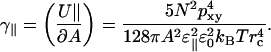 |
(16) |
Numerically this becomes γ‖ ≈ 0.02 mN/m which acts to reduce the area, but is completely negligible compared to the perpendicular interactions for all reasonable cutoffs. However, a contribution of this type would become important at very short distances. Now we turn to the interactions between dipoles in different sheets.
Interactions between dipoles in different layers
The electrostatic interaction energies between the different sheets may be recalculated in the dipole approximation from simulation data. They are attractive but small, of the order of 0.02 kJ mol−1 (per lipid), without any explicit shielding having been taken into account. This energy can be converted into a surface tension by multiplying with the dipole surface density (N/A) and some constant of the order of unity. This gives a contribution to the total surface tension of ∼10−2/ɛl mN/m. If we perform an analysis of these contributions, similar to that of the previous section, we see that this result is consistent with a situation where the interactions are not only between the lipid headgroups, but between the effective dipole moments, i.e., lipids plus water. The effective relative permittivity for interactions across the membrane is thus at least an order-of-magnitude larger than the relative permittivity of the hydrocarbon region alone. Interactions between the different sheets may therefore safely be neglected.
Effect of PME on the dipole tilt angle
The inclusion of long-range interactions by use of PME affects not just the energies and contributions to the virial at a given structure, but the structure of the system as well. The distribution functions for the total, the in-plane component, and the perpendicular component of the dipole moment are shown in Fig. 8 for simulations with PME and with cutoff. The distribution functions for the dipole tilt angle is shown in Fig. 9. Both figures show small but significant differences. Table 1 shows that PME increases the perpendicular component of the dipole by changing the tilt angle with ∼2° and reduces the size of the total dipole by 3–4%. This also affects contributions to energies and virial inside the cutoff. The total contribution to the surface tension from the nearest-neighbor distance, r0 ≈ 0.5 nm, out to infinity, will then be
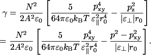 |
(17) |
When comparing different simulations from Table 1, we see that there is a correlation among p, pxy, and the area per lipid among different simulations. This is seen more clearly from Fig. 10 in which the area per lipid is shown versus the in-plane component of the dipole moment. The seven PME simulations are clustered in the upper-left corner of the figure, and the simulation without charge groups (IV) is quite close. The simulation with neutral charge groups (III) is found in the bottom-right corner whereas the simulations with charge groups of types I and II are found in between. Eq. 17 also gives the theoretical curve shown. This curve has been calculated in the following way. First we have to eliminate p from Eq. 17. In a plot of the data from Table 1 for p versus pxy (Fig. 11) it is evident that that the total dipole moment correlates quite well with the in-plane component. The straight-line fit from that figure has been inserted into Eq. 17 to give γ as a function of the single variable pxy. Then we have, from Eq. 2,
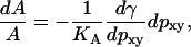 |
(18) |
which, assuming a constant KA, can be integrated to give
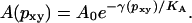 |
(19) |
Even if the right-hand side is an exponential of a fourth-degree polynomial, this is for practical purposes a straight line in the limited interval for pxy that is considered. All constants are known, either from experiment or simulation, except the integration constant, A0, which was determined to make the point (0.42, 0.60) fall on the line. The main result of this is that a small change in the size of the dipole components results in a fairly large change in area.
FIGURE 8.

Distribution of the magnitudes of the headgroup dipoles; total dipole (solid), in-plane component (dashed), and normal component (dotted). Comparison between simulation 2 using PME (A) and simulation 1 using cutoff (B). Values are given in both Debye (top) and e nm (bottom, e is the electron charge).
FIGURE 9.

Distribution of the dipole tilt angle with respect to the membrane normal from simulation 1 using cutoff (solid) and simulation 2 using PME (dashed).
FIGURE 10.

The area per lipid versus the in-plane dipole for the 15 simulations, together with a theoretical curve. The different cutoff methods are indicated with their respective labels.
FIGURE 11.

The total dipole versus the in-plane dipole for the 15 simulations, along with a straight-line fit.
The theoretical curve relies on the dipole approximation and the series expansion of Eq. 12, which most likely are not applicable down to nearest-neighbor distances. On the other hand, Fig. 12 shows almost perfect agreement between dipole and Coulomb energies outside a distance of ∼1.2 nm, which suggests that, at least, the long-range contributions are correct in this approximation. We also note that this analysis alone is not sufficient to describe the whole range of differences in areas. There are other circumstances, described earlier, that have effects equal in magnitude to that of a change in tilt angle. Therefore, the points in Fig. 10 also fall quite spread around the theoretical curve. Most notably, this analysis does not explain the area variation with system size. The finite size effect in PME simulations is quite small, ∼1% when going from 64 to 1024 lipids (see Table 1). Still, there is an increase of the perpendicular dipole component of 7%. In the cutoff simulations the effect on the area is larger (3.4% between 128 and 1024 lipids), but the perpendicular dipole component only increases by 1.6%. One might expect that a larger system containing more undulations should show a wider distribution in the tilt angle of the membrane normal and thus also in the tilt angle of the headgroup dipole. A more careful theoretical analysis does, however, show that this effect is logarithmic in system size. Numerically this gives a change in the average tilt of the membrane normal from 4° for a 64-lipid DPPC bilayer to 5° for a bilayer with 1024 lipids. It is therefore not surprising that we do not see any effect upon the tilt of the headgroup dipole from this.
FIGURE 12.

Interaction energy between headgroup dipoles as a function of interaction distance. Dipole approximation (dashed) compared to Coulomb interaction (solid). The inserted figure shows that at large distances (r > 1.5 nm) the dipole approximation yields the same result as the Coulomb interactions. Here the interaction between the perpendicular components of the dipoles, which goes as 1/r3 dominate. The dotted line shows the theoretical energy, Φ = p2/(4πɛ0r3), with the value for p2 as the average from the simulation. Data is taken from simulation 2.
We are in no doubt that it is the change in tilt angle that causes the change in area, and not the other way around. Trial simulations in which the area was held constant (NAT simulations) showed the same behavior for the tilt and size of the dipoles as the NpT simulation. The changes in tilt angle develop quite fast in a few hundred ps.
SUMMARY AND CONCLUSIONS
The electrostatic interactions in the headgroup region may at least for large distances be treated in a dipole approximation. Each monolayer is then divided into one sheet of perpendicular dipoles and one sheet of dipoles in the membrane plane. There is only one non-negligible contribution to the surface tension from long-range dipole-dipole interactions in this model. This is the (repulsive) interaction between the perpendicular components of the dipoles, which dominates over the in-plane components (which have an average attractive interaction) for two reasons—the slower decay with distance (1/r3 compared to 1/r6) and the weaker shielding. We were able to calculate the relative dielectric permittivities for the two types of interactions. We arrived at ɛ⊥ ≈ −10 for the perpendicular part by calculating the electrostatic potential over the headgroup region (Eq. 10), and ɛ‖ ≈ 80 for the in-plane interactions, by fitting the calculated energy to an analytical expression derived from a mean field theory (Eq. 13). The value obtained for ɛ‖ is somewhat surprising, as it is not the average of that for water and lipids but essentially equal to that of water. Our results for the relative permittivity is consistent with the results of Stern and Feller (2003) in the case where they considered the bilayer system as homogeneous, an assumption which might, as they stated themselves, be a little dubious.
The main difference between these two types of interactions is that the perpendicular components have a permanent average order, whereas the in-plane components fluctuate like dipoles in a two-dimensional dipole fluid. It has been shown a long time ago that dipole-dipole interactions in a dipole fluid (Stockmayer fluid) are adequately described using cutoff methods in Allen and Tildesley (1987, p. 165, and references therein). One might think that the situation would be different here since the dipoles are large, but this is not the case since the size of the dipoles is compensated by the presence of screening water.
The total contribution to the surface tension outside a cutoff of 1.8 nm from these interactions is ∼−10 mN/m which acts to increase the area per lipid, but only with ∼0.02 nm2. Despite a much smaller relative dielectric permittivity in the interior of the bilayer, the interactions between the different sheets are negligible, because of the relatively large separation of the layers. The distance between headgroups may be smaller across the water in a weakly hydrated system, but here the interactions are effectively shielded by a relative dielectric permittivity of 80.
The relative size of the dipole components is not fixed and even small changes in the tilt angle give rise to large effects on surface tension and area, since this also affects short-range interactions. Since the perpendicular components repel and the in-plane components attract each other, one would expect that an increase of the latter at the cost of the former would reduce the area per lipid. Simulations and analytical approximations confirm this intuitive idea and show that the effect is strong. A change in area per lipid from 0.64 to 0.54 nm2 requires only an increase of the in-plane dipole component by 15%. Cutoffs give a smaller z component and thus a smaller area than PME. Among the cutoff simulations, large nonspherical charge groups give the smallest z components and areas. We only partially understand this and it remains to find a satisfactory physical explanation for this effect on the tilt angle.
There are, however, other factors, which are not manifested in the relative sizes of the dipole components, that have a dramatic effect on the area. These are most clearly the system size and the level of hydration. The area increases with system size and decreases with hydration, but only for the cutoff simulations. The PME simulations remain virtually unaffected by these factors.
The tilt angle also affects the electrostatic potential over the monolayer. A larger z-component, which is seen in the PME simulations, will decrease the magnitude of the potential and bring it closer to its experimental value. It should also be noted that the potential is affected by the hydration. More water brings the value to approximately the same as for PME, i.e., closer to the experimental result.
In conclusion: PME simulations give areas in agreement with experiments for all investigated setups. At the same time they give electrostatic potentials that are too high, but significantly better than most cutoff simulations. Cutoff simulations do not suffer to any great extent from the omission of long-range electrostatics, at least not explicitly. They are, however, much more sensitive to details. The experimental area per lipid is obtained from large enough systems at proper hydration, with a careful treatment of the charge groups used for the cutoff. Our findings have a nice implication regarding the use of PME. It may be computationally more expensive than cutoffs, at least for large systems, but its insensitivity both to system size and the number of water molecules should enable us to use much smaller systems than are necessary when using cutoffs.
Acknowledgments
The authors express their gratitude to Clas Blomberg for helpful discussions.
This work has been carried out with support from the Gustafsson Foundation.
References
- Allen, M. P., and D. J. Tildesley. 1987. Computer Simulation of Liquids. Oxford University Press, Oxford, New York.
- Anézo, C., A. H. de Vries, H.-D. Höltje, D. P. Tieleman, and S.-J. Marrink. 2003. Methodological issues in lipid bilayer simulations. J. Phys. Chem. B. 107:9424–9433. [Google Scholar]
- Balgavý, P., M. Dubnièková, N. Kuèerka, M. A. Kiselev, S. P. Yaradaikin, and D. Uhríková. 2001. Bilayer thickness and lipid interface area in unilamellar extruded 1,2-diacylphosphatidylcholine liposomes: a small-angle neutron scattering study. Biochim. Biophys. Acta. 1512:40–52. [DOI] [PubMed] [Google Scholar]
- Berendsen, H. J. C., J. P. M. Postma, W. F. van Gunsteren, and J. Hermans. 1981. Intermolecular Forces. B. Pullman, editor. Reidel, Dordrecht, Holland. 331.
- Berendsen, H. J. C., J. P. M. Postma, A. DiNola, and J. R. Haak. 1984. Molecular dynamics with coupling to an external bath. J. Chem. Phys. 81:3684–3690. [Google Scholar]
- Berendsen, H. J. C., D. van der Spoel, and R. van Drunen. 1995. gromacs: a message-passing parallel molecular dynamics implementation. Comput. Phys. Comm. 91:43–56. [Google Scholar]
- Berger, O., O. Edholm, and F. Jähnig. 1997. Molecular dynamics simulation of a fluid bilayer of dipalmitoylphosphatidylcholine at full hydration, constant pressure, and constant temperature. Biophys. J. 72:2002–2013. [DOI] [PMC free article] [PubMed] [Google Scholar]
- Bloom, M., E. Evans, and O. G. Mouritsen. 1991. Physical properties of the fluid lipid-bilayer component of cell membranes: a perspective. Quar. Rev. Biophys. 24:293–397. [DOI] [PubMed] [Google Scholar]
- Braganza, L. F., and D. L. Worcester. 1986. Structural changes in lipid bilayers and biological membranes caused by hydrostatic pressure. Biochemistry. 25:7484–7488. [DOI] [PubMed] [Google Scholar]
- Brockman, H. 1994. Structural changes in lipid bilayers and biological membranes caused by hydrostatic pressure. Chem. Phys. Lipids. 73:57–79.8001185 [Google Scholar]
- Chiu, S. W., M. Clark, V. Balaji, S. Subramaniam, H. Scott, and E. Jakobsson. 1995. Incorporation of surface tension into molecular dynamics simulation of an interface: a fluid phase lipid bilayer membrane. Biophys. J. 69:1230–1245. [DOI] [PMC free article] [PubMed] [Google Scholar]
- Chiu, S. W., M. M. Clark, E. Jakobsson, S. Subramaniam, and H. L. Scott. 1999. Optimization of hydrocarbon chains interaction parameters: application to the simulation of fluid phase lipid bilayers. J. Phys. Chem. B. 103:6323–6327. [Google Scholar]
- Chiu, S. W., S. Vasudevan, E. Jakobsson, R. J. Mashl, and H. L. Scott. 2003. Structure of sphingomyelin bilayers: a simulation study. Biophys. J. 85:3624–3636. [DOI] [PMC free article] [PubMed] [Google Scholar]
- Darden, T., D. York, and L. Pedersen. 1993. Particle mesh Ewald: An N·log(N) method for Ewald sums in large systems. J. Chem. Phys. 98:10089–10092. [Google Scholar]
- Essmann, U., L. Perera, M. L. Berkowitz, T. Darden, H. Lee, and L. G. Pedersen. 1995. A smooth particle mesh Ewald method. J. Chem. Phys. 103:8577–8593. [Google Scholar]
- Feller, S. E., and R. W. Pastor. 1996. On simulating lipid bilayers with an applied surface tension: periodic boundary conditions and undulations. Biophys. J. 71:1350–1355. [DOI] [PMC free article] [PubMed] [Google Scholar]
- Feller, S. E., R. W. Pastor, A. Rojnuckarin, S. Bogusz, and B. R. Brooks. 1996. Effect of electrostatic force truncation on interfacial and transport properties of water. J. Phys. Chem. 100:17011–17020. [Google Scholar]
- Feller, S. E., R. M. Venable, and R. W. Pastor. 1997. Computer simulation of a DPPC phospholipid bilayer: structural changes as a function of molecular surface area. Langmuir. 13:6555–6561. [Google Scholar]
- Feller, S. E., and R. W. Pastor. 1999. Constant surface tension simulations of lipid bilayers: the sensitivity of surface areas and compressibilities. J. Chem. Phys. 111:1281–1287. [Google Scholar]
- Feller, S. E. 2000. Molecular dynamics simulations of lipid bilayers. Curr. Opin. Colloid Interface Sci. 5:217–223. [Google Scholar]
- GROMACS User Manual, Version 3.2. 2004. Department of Biophysical Chemistry, University of Groningen, The Netherlands, http://www.gromacs.org.
- van Gunsteren, W. F., S. R. Billeter, A. A. Eising, P. H. Hunenberger, P. Kruger, A. E. Mark, W. R. P. Scott, and I. G. Tironi. 1996. Biomolecular Simulation: The GROMOS96 Manual and User Guide. Hochschulverlag AG an der ETH Zurich and BIOMOS b.v., Zürich, Groningen.
- Hess, B., H. Bekker, H. J. C. Berendsen, and J. G. E. M. Fraaije. 1997. lincs: a linear constraint solver for molecular simulations. J. Comput. Chem. 18:1463–1472. [Google Scholar]
- Hoover, W. G. 1985. Canonical dynamics: equilibrium phase-space distributions. Phys. Rev. A31:1695–1697. [DOI] [PubMed] [Google Scholar]
- Jorgensen, W., and J. Tirado-Rives. 1988. The OPLS potential functions for proteins. Energy minimizations for crystals of cyclic peptides and crambin. J. Am. Chem. Soc. 110:1657–1666. [DOI] [PubMed] [Google Scholar]
- Lagüe, P., R. W. Pastor, and B. R. Brooks. 2004. Pressure-based long-range correction for Lennard-Jones interactions in molecular dynamics simulations: application to alkanes and interfaces. J. Phys. Chem. B. 108:363–368. [Google Scholar]
- Lide, D. R. 1999–2000. CRC Handbook of Chemistry and Physics, 80th Ed. CRC Press, Boca Raton, FL.
- Lindahl, E., and O. Edholm. 2000a. Mesoscopic undulations and thickness fluctuations in lipid bilayers from molecular dynamics simulations. Biophys. J. 79:426–433. [DOI] [PMC free article] [PubMed] [Google Scholar]
- Lindahl, E., and O. Edholm. 2000b. Spatial and energetic-entropic decomposition of surface tension in lipid bilayers from molecular dynamics simulations. J. Chem. Phys. 113:3882–3893. [Google Scholar]
- Lindahl, E., B. Hess, and D. van der Spoel. 2001. GROMACS 3.0: a package for molecular simulation and trajectory analysis. J. Mol. Mod. 7:306–317. [Google Scholar]
- Majer, V., and V. Svoboda. 1985. Enthalpies of Vaporization of Organic Compounds. IUPAC Chemical Data Series Number 32, Blackwell Scientific Publications, Oxford, UK.
- McIntosh, T. J. 2000. Short-range interactions between lipid bilayers measured by x-ray diffraction. Curr. Opin. Struct. Biol. 10:481–485. [DOI] [PubMed] [Google Scholar]
- Miyamoto, S., and P. A. Kollman. 1992. SETTLE: an analytical version of the SHAKE and RATTLE algorithms for rigid water models. J. Comput. Chem. 13:952–962. [Google Scholar]
- Nagle, J. F., and S. Tristram-Nagle. 2000. Structure of lipid bilayers. Biochim. Biophys. Acta. 1469:159–195. [DOI] [PMC free article] [PubMed] [Google Scholar]
- Nosé, S. 1984. A molecular dynamics method for simulations in the canonical ensemble. Mol. Phys. 55:255–268. [Google Scholar]
- Pandit, S. A., and M. L. Berkowitz. 2002. Molecular dynamics simulation of dipalmitoylphosphatidylserine bilayer with Na+ counterions. Biophys. J. 82:1818–1827. [DOI] [PMC free article] [PubMed] [Google Scholar]
- Parrinello, M., and A. Rahman. 1981. Polymorphic transitions in single crystals: a new molecular dynamics method. J. Appl. Phys. 52:7182–7190. [Google Scholar]
- Pastor, R. W. 1994. Computer simulations of lipid bilayers. Curr. Opin. Struct. Biol. 4:486–492. [Google Scholar]
- Patra, M., M. Karttunen, M. T. Hyvönen, E. Falck, P. Lindqvist, and I. Vattulainen. 2003. Molecular dynamics simulations of lipid bilayers: major artifacts due to truncating electrostatic interactions. Biophys. J. 84:3636–3645. [DOI] [PMC free article] [PubMed] [Google Scholar]
- Petrache, H. I., S. W. Dodd, and M. F. Brown. 2000. Area per lipid and acyl length distributions in fluid phosphatidylcholines determined by 2H NMR spectroscopy. Biophys. J. 79:3172–3192. [DOI] [PMC free article] [PubMed] [Google Scholar]
- Ryckaert, J.-P., and A. Bellemans. 1975. Molecular dynamics of liquid n-butane near its boiling point. Chem. Phys. Lett. 30:123–125. [Google Scholar]
- Saiz, L., and M. L. Klein. 2002. Computer simulation studies of model biological membranes. Acc. Chem. Res. 35:482–489. [DOI] [PubMed] [Google Scholar]
- Scott, H. L. 2002. Modeling the lipid components of membranes. Curr. Opin. Struct. Biol. 12:495–502. [DOI] [PubMed] [Google Scholar]
- Stern, H. A., and S. E. Feller. 2003. Calculation of the dielectric permittivity profile for a nonuniform system: application to a lipid bilayer simulation. J. Chem. Phys. 118:3401–3412. [Google Scholar]
- Tieleman, D. P., and H. J. C. Berendsen. 1996. Molecular dynamics simulations of a fully hydrated dipalmitoylphosphatidylcholine bilayer with different macroscopic boundary conditions and parameters. J. Chem. Phys. 105:4871–4880. [Google Scholar]
- Tieleman, D. P., S.-J. Marrink, and H. J. C. Berendsen. 1997. A computer perspective of membranes: molecular dynamics studies of lipid bilayer systems. Biochim. Biophys. Acta. 1331:235–270. [DOI] [PubMed] [Google Scholar]
- Tobias, D. J. 2001. Electrostatics calculations: recent methodological advances and applications to membranes. Curr. Opin. Struct. Biol. 11:253–261. [DOI] [PubMed] [Google Scholar]
- Venable, R. M., B. R. Brooks, and R. W. Pastor. 2000. Molecular dynamics simulations of gel (LβI) phase lipid bilayers in constant pressure and constant surface area ensembles. J. Chem. Phys. 112:4822–4832. [Google Scholar]
- Weast, R. C. 1977–1978. CRC Handbook of Chemistry and Physics, 58th Ed. CRC Press, Cleveland, OH.
- Wohlert, J. 2001. Construction of Lennard-Jones potentials for lipid simulations. Master thesis, Kungliga Tekniska högskolan (Royal Institute of Technology), Stockholm, Sweden.