Abstract
The motion of the tectorial membrane (TM) with respect to the reticular lamina subserves auditory function by bending the outer hair cell bundles and inducing fluid flows that shear the inner hair bundles in response to sound energy. Little is currently known about its intrinsic elasticity or about the relation between the mechanical properties and function of the membrane. Here we subdivide the TM into three longitudinal regions and five radial zones and map the shear modulus of the TM using atomic force microscopy, and present evidence that the TM elasticity varies radially, after the distribution of type A collagen fibrils. This is seen most dramatically as a decrease in shear modulus in the neighborhood of the sensory hair cells; we argue that this inhomogeneity of properties not only protects the hair bundles but also increases the energy efficiency of the vibrational shearing during sound transduction.
INTRODUCTION
The mammalian tectorial membrane (TM) remains something of a mystery more than a century after its discovery by Alfonse Corti in the mid-1800s. Although it has been often described in qualitative terms, the quantitative literature about the mechanical properties of the tissue is sparse. The membrane, which overlies the organ of Corti (OC) and couples to varying degrees with the inner (IHCs) and outer hair cells (OHCs) (Lim, 1972; Zwislocki, 1979), is essential for transmitting acoustic energy to the hair bundles, where mechanical motion is transduced to electrical currents that are required for proper functioning of the ear (Hudspeth, 1985). The structural integrity of the TM, which is thought to depend on the expression of both α- and β-tectorin (Legan et al., 1997), is critical; disruptions in either of two protein domains of α-tectorin have been shown to cause hearing loss, with the range of frequencies affected in a domain-sensitive manner (Naz et al., 2003), whereas disruptions in a third protein domain result in a TM devoid of noncollagenous matrix and detached from the OC. In the latter case, in which normal TM–hair-cell coupling is lost, the basilar membrane (BM) retains its sharp tuning curve, but amplification is reduced by 35–40 dB (Legan et al., 2000). Similarly, disruptions of Otog, a gene that encodes the protein otogelin and thus establishes fiber distribution and orientation, portend the progression of severe to profound deafness in homozygous recombinant mice (Simmler et al., 2000). In humans, mutations in COL11A2 are believed, based on evidence in the mouse model, to alter the shape and size of the TM and again to disrupt the normal regular organization of collagen fibrils. In mice, these abnormalities were accompanied by a decrease in hearing sensitivity of 40–50 dB (McGuirt et al., 1999).
Interest in the TM has increased in recent months after the publication of a comparative analysis of human, chimpanzee, and mouse genomes. In that study, Clark et al. (2003) quantified human-specific evolutionary pressure at the level of the gene and found that not only has there been significant human-specific development in hearing but that the single-highest value of human-specific evolutionary pressure occurs in the gene whose product encodes α-tectorin. Because α-tectorin is expressed exclusively in the inner ear (Legan et al., 1997), and because of differences between humans and chimps in this and other hearing-related genes, the authors postulate a genetic link between hearing acuity and the acquisition of speech and conclude that their results “strongly motivate a detailed assessment of the nature of hearing differences between humans and chimpanzees” (Clark et al., 2003).
Understanding the role of the TM in hearing, and in hearing loss, requires determination of the mechanical properties of the tissue and how they relate to the relative shearing of the TM with respect to the reticular lamina (RL) and to the bending of hair bundles. In this study, we use an atomic force microscope (AFM) to indent samples of the TM isolated from the guinea pig (Cavia porcellus). Using automated algorithms to fit nonlinear models of isotropic contact mechanics, we spatially map the shear modulus, G (N/m2), of the TM. Unlike stiffness (N/m), the shear modulus quantifies the intrinsic material property of sample rigidity and is independent of instrumentation and methodology. Quantitative models of biological systems like our finite element model (FEM) of the cochlea (Cai and Chadwick, 2003; Cai et al., 2004) require knowledge of the intrinsic properties of the anatomical components of the model. The shear modulus of the TM has important implications for hearing: a decrease in G indicates a decrease in rigidity or an increase in softness. If the TM were too soft in the neighborhood of OHC bundles, the stereocilia would be unable to bend appropriately, and hearing would be impaired. On the other hand, the stereocilia bundles are susceptible to acoustic trauma (Clark and Pickles, 1996) and could easily be damaged by overstimulation if the TM were locally too rigid. These local constraints, however, do not apply to the global properties of the TM.
MATERIALS AND METHODS
Tissue preparation, artificial endolymph, and dissection procedures
All animal procedures were conducted according to approved National Institutes of Health (NIH) animal protocol number 1049-02. Tissue samples from 10 juvenile female pigmented guinea pigs weighing between 150 g and 200 g were used in these experiments. All animals included in the study tested positive for pinna (startle) response. Before sacrifice and dissection, we prepared a solution of artificial endolymph (AE), comprising 2 mM NaCl, 0.02 mM CaCl2, 174 mM KCl, and Hepes (buffered to pH 7.3) (Abnet and Freeman, 2000). The AE was made in a quantity sufficient for all of our dissections to ensure that the concentration of elements was constant throughout the experiment. Animals were euthanized with CO2 gas and decapitated, whereupon their bullae were removed and transferred immediately to AE-filled petri dishes. Each bulla was scored and broken under a dissecting microscope, and the cochlea was exposed. We carefully removed sections of the bony casing of the cochlea and then teased away from the organ of Corti individual samples of the TM using a bristle from a fine sable-bristled paintbrush. These samples were then transferred with a micropipette to dishes coated with Cell-Tak (BD Biosciences, Bedford, MA) and gently tapped with the sable bristle to adhere the tissue to the Cell-Tak. All samples that appeared to come to rest with the cover net up were discarded, so that we limited our mechanical testing to the surface that interfaces with the sensory hair cells. Upon visual inspection, we also discarded any samples that appeared to be folded or damaged in any way. Thermal and acoustic environments in which the AFM measurements were made were relatively constant from session to session. During the course of the 2–3-h dissection and subsequent AFM analyses (another 2–3 h), tissue samples remained submerged in the uniform bath of AE.
Data collection
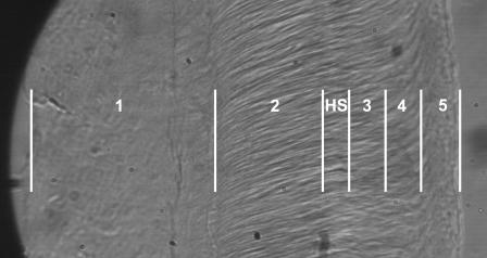
We subdivided the tissue into three longitudinal regions (basal, middle, and apical) and five radial zones (Fig. 1), such that zones 1 and 2 are on the limbal side of the Hensen's stripe, zones 3 and 4 are the neighborhoods of the IHCs and OHCs, respectively, and zone 5 represents the marginal band. Although the boundaries of the zones are not clearly defined, our radial bands correspond approximately with those defined by Lim (1972) such that zone 1 represents the limbal zone, zones 2 and 3 constitute the middle zone, and zones 4 and 5 constitute the marginal zone. We were consistently and reliably able to determine the position of Hensen's stripe by adjusting the focus during the data collection.
FIGURE 1.
Photomicrograph of a basal section of the tectorial membrane, with annotations denoting the approximate discretization of the radial zones. Measurement zones (across at the top) are defined relative to Hensen's stripe (HS) such that zone 1 corresponds roughly to the limbal zone defined by Lim (1972), and zones 3–5 are approximately uniformly spaced on the marginal side of HS. Zone 3 represents the approximate location of the IHCs, and zone 4 represents the neighborhood of the OHC articulations.
All AFM force-displacement curves were collected, using a commercial instrument (Bioscope, Digital Instruments, Santa Barbara, CA), within 2 or 3 h of transfer to the Cell-Tak-coated dishes. From 10 animals, we collected ∼1000 force-displacement curves spanning all radial zones and longitudinal regions. After each sample was indented, the cantilever position was moved longitudinally in increments of ∼5 μm before another force-displacement curve was generated. After collecting 10–20 curves in a particular neighborhood, we shifted the cantilever position radially to probe the next zone, continuing until we had spanned the radial extent of the sample. To minimize the effects of finite sample thickness (see Discussion), we limited indentation to 750 nm.
Probe tip and contact model selection
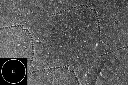
Initially, all data were collected using standard silicon nitride (Si3N4) cantilever probes (Digital Instruments) having a nominal spring constant of 0.06 N/m and four-sided pyramidal tips. In the electron micrograph of Fig. 2, the square box in the inset shows the contact area of a pyramidal tip indented to 300 nm; with a Si3N4 tip, the area of contact is approximately on the scale of a single stereocilium. In contrast, hair bundles, which are interconnected and deflect as a unit, span ∼5 μm. These considerations motivated a further series of experiments in which we affixed 9.6-μm-diameter polystyrene microspheres (Interfacial Dynamics, Portland, OR) to the pyramidal tips, as described in Dimitriadis et al. (2002). The relationship of the area of contact of the microsphere with the TM is represented by the circle in the inset of Fig. 2.
FIGURE 2.
Scanning electron image of the imprints of the stereocilia of the OHCs. The inset box depicts the contact area for the AFM probe tips; the square approximates the contact area of a pyramid indented to a depth of 300 nm, and the circle represents the area of contact for a sphere indented to 300 nm. The diameter of the circle is 2.4 μm. (See Materials and Methods for the description of microscopy techniques.)
The widely used Hertz model quantifies the indentation of an elastic half-space with a spherical probe. This model is appropriate if a microsphere is affixed to a Si3N4 tip but, since the standard silicon nitride AFM probe tip can be approximated as a regular four-sided pyramid, can otherwise introduce significant error into the analysis of AFM data. In contrast, the Bilodeau model (Bilodeau, 1992) describes the indentation of an elastic half-space with a regular n-sided pyramidal probe and thus facilitates a more accurate calculation of shear modulus from standard AFM probes. When n = 4, the Bilodeau model predicts shear modulus as
 |
where P is the force on the probe, ν is Poisson's ratio, α is the complement of the semivertex angle (for the standard Si3N4 tip, α = 55°; Digital Instruments, 1996), and δ is the indentation depth. We note, however, that the tip is angled on the cantilever ∼10° from the vertical. The error introduced by this mounting angle has been previously described (Costa and Yin, 1999; Heim et al., 2004); here we address the problem simply by using an angle of α = 45°. With a spherical tip of radius R, on the other hand, the shear modulus, G, is given by the Hertz model (Landau and Lifshitz, 1970) as
 |
The TM is assumed to be incompressible at scan rates of 1–2 Hz; for the incompressible case, ν = 0.5 and E = 3G, where E is Young's modulus. This low frequency, however, represents a limitation of our analysis; the TM is known to have a frequency-dependent point impedance (Freeman et al., 2003), which is likely to be reflected in a frequency dependence of the TM shear modulus. Clearly, it follows that speculations about the TM based on relatively static measurements should be interpreted cautiously and merit validation by studies at acoustic frequencies.
Data analysis
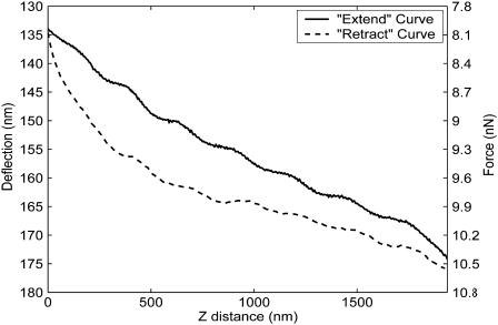
Before analysis, all force-distance curves were visually inspected; curves that were wavy, or that did not appear to contain a noncontact portion, were considered likely to have resulted from optical interference or false engagement, respectively, and were discarded. Approximately 10% of our data, typified by the curve of Fig. 3, were thus rejected. The order of the remaining curves was then randomized, and each was objectively evaluated without prior knowledge of its source. In all cases, we minimized the effects of adhesive forces by analyzing only “extend” data (Vinckier and Semenza, 1998), which represent the movement of the AFM head toward the sample.
FIGURE 3.
Typical rejected AFM force-distance data. Upon visual inspection, curves that were wavy or that did not appear to have a relatively horizontal noncontact region were discarded. In this and all subsequent force-distance curves, the head of the AFM is approaching the sample (extending) and substrate as the z-distance decreases.
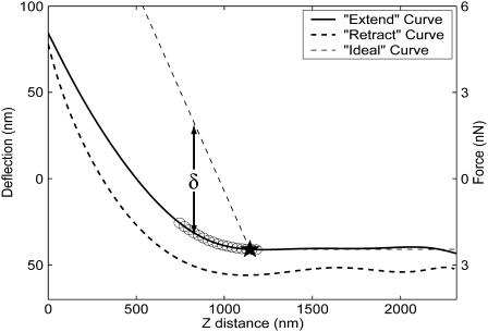
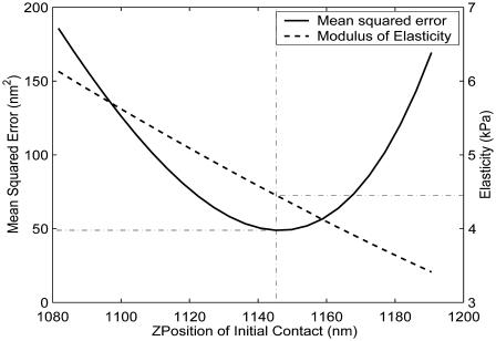
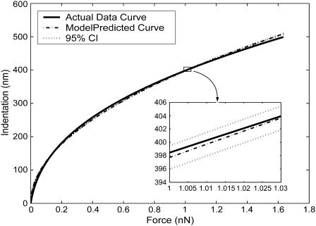
In force-imaging mode, the AFM provides data representing the deflection versus z-position of the cantilever. Knowing the stiffness k of the (Hookean) cantilever, and using the cantilever deflection d measured directly by the instrument, determination of P (= kd) is trivial. Once the geometry of the tip is established (and an appropriate model of contact is selected), determination of the sample elasticity becomes largely a problem of determination of sample indentation δ. This is nontrivial and requires first ascertaining the initial point of contact. To facilitate the determination of the contact point and the calculation of elasticity, we wrote a series of programs that automate the reconstruction and analysis of AFM force-distance curves. The software makes an initial guess of the contact point and then compares the curves to idealized hard-surface deflections (Radmacher et al., 1995) to compute indentation values (Fig. 4). These indentations, along with calculated forces, are fit using a nonlinear fitting algorithm to the Bilodeau equation to extract G. Unless explicitly stated otherwise, all values reported in this article are shear moduli and are referred to generically as elasticity. Along with a modulus the algorithm returns the level of residual error, quantifying deviation from the model-predicted curve. Using this information, we shift the guessed contact point along the curve in the range of the initial guess, recomputing and recording mean-squared errors as a function of z-position of initial contact. Fig. 5 shows a sample curve relating error to the vertical position of the AFM probe (solid line). A dashed line also depicts the sensitivity of the model, revealing how the calculated shear modulus changes with the guess of initial contact point; the actual contact point is taken to be that which minimizes residual error. The data are then plotted along with the 95% confidence interval of the best model-predicted curve (Fig. 6) to show how well the indentations conform to theory.
FIGURE 4.
Representative AFM force-distance curve. Some degree of hysteresis is shown between the (solid) extend curve (probe head approaching sample) and the (dotted) retract curve (probe head withdrawing). The ○ indicate the range of data evaluated as candidates for point of initial contact. At each of these candidate points, an ideal curve (dashed lines) is generated, indicating modeled tip deflection on a hard material. The difference between the ideal and extend curves is computed to quantify sample indentation, δ. The slope of the ideal curve has been exaggerated to facilitate visualization of indentation.
FIGURE 5.
Mean-squared error as a function of z-position of initial contact. In this plot, the y axis shows the Young's modulus, E, rather than the shear modulus. The final value of E is calculated at the z-position that minimizes residual error. The presence of a single clearly defined local minimum provides confidence that the model has converged to a best-fit value of E. The slope of the plot of Young's modulus versus z (dashed line) reveals the sensitivity of the analyses, for a given model of contact mechanics, to the selection of the initial contact point.
FIGURE 6.
The predicted curve, the 95% confidence interval of the predicted curve, and the best-fit model-predicted curve for the data of Fig. 3. The tightness of the fit along the entire length of the predicted curve is reflected by a relatively low minimum mean-squared error of 50 nm2 (see Fig. 5).
Because of the known tip geometry, the Bilodeau model is assumed to provide the most robust and reliable measure of elasticity when using an unmodified Si3N4 probe. For the data represented in Fig. 4, the Bilodeau model predicts a shear modulus of 2.1 kPa (Young's modulus = 6.4 kPa). Note that although the tip sharpness may change during the course of an experiment (and, in extreme cases, may affect the accuracy of Bilodeau calculations), the vertex angle of the pyramid does not change. In contrast, the use of the Hertz model with an unmodified Si3N4 cantilever requires approximating the tip of a four-sided pyramid as a hemisphere. Depending on the assumption regarding tip sharpness, this may produce highly variable and unreliable results. For example, the Si3N4 tip has a nominal tip radius of curvature ranging from 5 nm to 10 nm for a “very good tip” (Digital Instruments, 1999) to 100 nm for a “moderately blunt tip” (Dimitriadis et al., 2002); the Hertz-predicted Young's modulus for the data represented by Fig. 4 would vary accordingly from 68.3 kPa (5-nm radius) to 15.3 kPa (100-nm radius). For each AFM curve generated with an unmodified pyramidal tip, we therefore used the Bilodeau model to compute a single best-fit value of the shear modulus. On the other hand, all data sets generated with microspheres affixed to the cantilever tip were analyzed using the Hertz model.
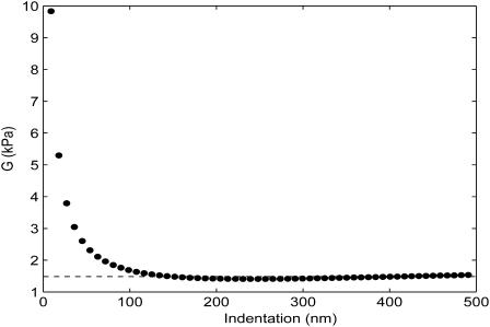
As previously described, the intrinsic sample elasticity is independent of probe tip and indentation parameters. After each analysis, we plotted shear modulus versus indentation δ, and we limited our evaluations to the regions for which the modulus of elasticity is relatively invariant with indentation (Fig. 7). All results were then recorded in a spreadsheet along with source information and relevant parameters. Outliers for all data sets were removed objectively by iterative application of the Grubbs test (Grubbs, 1969), and the remaining data were evaluated and compared statistically using unpaired, two-sided Student's t-tests. Sample variances were not assumed to be equal for these comparisons.
FIGURE 7.
Elasticity versus indentation (δ) for the evaluation of the data represented in Fig. 4. After an initially nonlinear response at low force (very near initial contact), the shear modulus calculation approaches a steady value. The horizontal line indicates the minimal-error value of elasticity (G = 1.45 kPa) reported by the program. In the horizontal region, the data indicate the independence of elasticity and indentation. The meaning of the nonhorizontal region has not been fully explored and may reflect the interaction of repulsive surface forces on the cantilever, noise in the vicinity of initial contact, or both.
Electron microscopy
For the scanning electron microscopy image of Fig. 2, the TM was fixed in 2% glutaraldehyde in buffered Hepes, as previously described. The sample was washed several times, critical-point dried, and rotary shadowed with platinum. The ventral surface of the TM was viewed and photographed with a Hitachi S4500 field-emission scanning electron microscope (Hitachi Instruments, San Jose, CA).
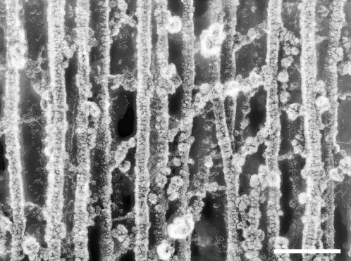
For the rapid-freeze, deep etch image of Fig. 8, the guinea pig OC was dissected from the cochlea and fixed for 2 h in 2% glutaraldehyde in Hepes buffered phosphate-buffered saline (PBS) at pH 7.3. The sample was washed several times in distilled water and rapidly frozen by contact with a copper block cooled with liquid helium. The specimen was then freeze fractured at −150°C, allowed to etch for 10 min at −100°C, and rotary shadowed with platinum and carbon. A section of type A fibril network was photographed at 200 kV in a Jeol 200CX electron microscope (Jeol, Peabody, MA). The image is shown in reverse contrast, where platinum deposits appear white.
FIGURE 8.
Rapid-freeze, deep-etch image of type A fibril domain. The scale bar is 90 nm, the dimension of a side of the square contact region of the pyramidal tip indented to 50 nm. (See Materials and Methods for the description of microscopy techniques.)
Finite element modeling of energy dissipation
We developed a hybrid analytical/numerical approach for modeling the cochlea (Cai and Chadwick, 2003), in which we let the WKB perturbation method (Bender and Orszag, 1978) determine the axial propagation of the traveling wave in the hearing organ and used finite-element analysis in the cross sections of the cochlea that were divided into fluid and elastic domains. The basilar membrane was modeled as an orthotropic clamped plate, and the TM and the OC were modeled as inhomogeneous elastic domains. The cochlear fluid was treated as viscous and incompressible, with viscous effects confined to oscillatory boundary layers, and to the thin gap between the RL and the lower surface of the TM. We solved the fluid-solid interaction eigenvalue problem for the axial wavenumber, fluid pressure, and the vibratory relative motions of the cochlear partition as a function of frequency using an iterative algorithm. Considering the TM as a Voigt solid (Cai and Chadwick, 2003), we normalized the TM displacements by the transverse motion of the middle of the basilar membrane and calculated the cycle-averaged energy dissipation per unit volume, e = π(σijIɛijR − σijRɛijI). Here, σij and ɛij are the stress and strain tensors, I and R represent imaginary and real parts, respectively, and summation over indices i and j is understood. Calculations of energy dissipation were made by integrating e over the TM cross sectional area. These values were compared for the apical and basal regions of the TM, assuming uniform values of TM elasticity equal to our lowest and highest values of G measured in each region and then assuming radially variant shear moduli after our measurements.
RESULTS AND DISCUSSION
Finite thickness effects
We note that both the Hertz and Bilodeau models are strictly valid only for the indentation of infinitely thick elastic, isotropic halfspaces. It is worthwhile to quantify the error introduced into our calculations by the finite thickness of the TM. Dimitriadis et al. (2002) address the use of the Hertz model (with a spherical indenter) for thin materials. When a microsphere is affixed to the AFM probe and the sample is thin, bonded, and incompressible, calculations of elasticity, G, can be corrected by F ∝ G × CF, where CF is a correction factor given by
 |
and  (For a probe of R = 5 μm, a δmax of 750 nm, and a sample height of h = 10 μm, χ = 0.19, and CF = 1.27.) Moreover, we see that (for a given indentation and force) as the correction factor increases, our calculated G decreases. This suggests that for measurements of the TM on the thinnest (limbal) portion, where the tissue thins to roughly 10 μm, the finite thickness of the sample would lead to an overestimation of elasticity by ∼27%. The error due to finite thickness for the more general case where the tissue varies from 20 μm to 40 μm and the maximal indentation is constrained to 750 nm is on the order of 12%–6%, respectively. Noting that these potential errors are smaller than the measured differences in elasticity between the different radial zones, it is reasonable to conclude that the measured radial variability in elasticity reflects changes in mechanical properties rather than thickness effects.
Unfortunately, we have not yet been able to determine simultaneously both sample height and the force-indentation relationship. Thus although the formula of Dimitriadis et al. (2002) allows us to approximate the error when using a microsphere-affixed probe, it does not enable us to accurately correct for finite thickness effects. Moreover, minimizing the error by limiting indentation is also problematic; even when using extremely soft (0.06-N/m) commercially available AFM cantilevers, there is generally insufficient data for indentations less than 500 nm to obtain good fits to the appropriate model of contact mechanics. In the uncorrected mode, we are pushing the limits of using the AFM to indent such thin samples. We note further that no finite-thickness correction is yet available for the Bilodeau model; although shear moduli are reported from both the pyramidal probe and the microsphere-tipped probe, we note that the error in our measurements of the limbal region (zone 1) is likely to be ∼27% with a microsphere affixed. A similar value is expected for Bilodeau analyses using unmodified Si3N4 tips. Thus although we cannot provide accurate corrections for these values, we can at least obtain a sense of the magnitude of errors that finite thickness imparts in our measurements.
Shear modulus of the TM
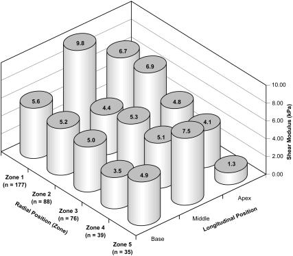
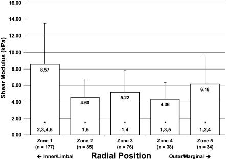
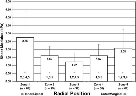
The results of our AFM analyses of TM elasticity are summarized in Figs. 9–11. In Fig. 9, we show the spatial distribution of shear moduli by both longitudinal and radial position, for data obtained using unmodified Si3N4 tips. Fig. 10 shows the combined Bilodeau (pyramid-tipped) data without regard for longitudinal position. This figure makes clearer the trend toward softening in the central zones of the tissue. Fig. 11 shows similar aggregate (all-region) data obtained with a microsphere-affixed tip and analyzed with the Hertz model. Again we see a general softening in the central portion of the tissue. In Figs. 10 and 11, zones with statistically different shear moduli (p < 0.01) zones are indicated by the numbers at the base of the mean modulus bars.
FIGURE 9.
Longitudinal and radial variation in the shear modulus of the tectorial membrane. Values on the columns are mean shear moduli, in kPa. Errors in measurements of the limbal zone (zone 1) are likely to be large due to the local thinning of the tissue. All data for this figure were collected using unmodified Si3N4 tips and were analyzed using the Bilodeau model. (See Finite Thickness Effects for a discussion of the magnitude of errors imparted by the finite thickness of the TM.)
FIGURE 10.
Distribution of shear moduli in the guinea pig tectorial membrane. Aggregate mean and standard deviations of shear moduli for pyramid-probed samples, inclusive of tissue from the basal, middle, and apical portions of the TM. Zone 3 corresponds approximately to the location of the IHCs, and zone 4 represents the position of the OHC attachments. The numbers at the bottom of each bar (beneath the asterisks) indicate other zones from which the current zone is significantly different (α = 0.01).
FIGURE 11.
Distribution of shear moduli in the guinea pig tectorial membrane. Aggregate mean and standard deviations of shear moduli for microsphere-probed samples, inclusive of tissue from the basal, middle, and apical portions of the TM. The numbers at the bottom of each bar (beneath the asterisks) indicate other zones from which the current zone is significantly different (α = 0.01).
We report here, to our knowledge, the first reliable indication of a radial gradient in the elasticity of the mammalian TM. Specifically, we find that the TM is more rigid toward the inner (limbal) zones where the tissue attaches to the modiolus and generally softest in the neighborhood of the sensory hair cells. In paired (zone-by-zone), one-tailed Student's t-tests of the aggregate pyramid data, we find that G is significantly lower in zone 4 (p < 0.01) compared to zones 1, 3, and 5 (p = 0.27 compared to zone 2). With the microsphere data, the situation appears slightly different: with these data, we find that the shear modulus of zone 3 is significantly lower than that of all other zones (p < 0.01). The meaning of this difference between pyramid (Bilodeau) and microsphere (Hertz) data is not clear; the trend toward softening in the interior radial zones, however, is apparent with both tips. Additionally, we summarize in Table 1 the statistical significance of the (paired) differences in moduli along the length of the guinea pig TM. In general, although radial zones in some regions differed sporadically from corresponding zones in other longitudinal regions, we did not observe a general trend in the longitudinal elasticity of the TM.
TABLE 1.
Significance of longitudinal variation of elasticity of the tectorial membrane
| Comparing | Significant? (p < 0.01) | Comparing | Significant? (p < 0.01) | Comparing | Significant? (p < 0.01) |
|---|---|---|---|---|---|
| B1 : M1 | Yes | B1 : A1 | M1 : A1 | Yes | |
| B2 : M2 | B2 : A2 | M2 : A2 | |||
| B3 : M3 | B3 : A3 | M3 : A3 | |||
| B4 : M4 | B4 : A4 | Yes | M4 : A4 | ||
| B5 : M5 | B5 : A5 | M5 : A5 | Yes |
Significance of differences in elasticity moduli along the length of the guinea pig TM. B = base, M = middle, and A = apex. Numbers refer to radial zones. Thus, for example, the elasticity of the basal region of the TM is significantly different from that of the middle region in zone 1 (p < 0.01) but not in zone 2. Data generated with the microsphere-affixed probe were excluded from this analysis.
We note that the TM is assumed to be stable in the AE bath during the experiments; at no time did we observe apparent changes in the mechanical properties of the TM over the time course of our experiments, though we cannot determine if any significant, early-phase hardening or softening took place during the dissection.
For a purely linearly isotropic material, a single constant suffices to describe the sample elasticity. Regardless of the direction in which a sample is probed (i.e., whether one imparts a tangential or a normal force, for instance), the application of a suitable model will provide a single elastic constant. Knowing Poisson's ratio of the material, conversion between shear and Young's moduli is trivial: G = E/(2(1 + ν)). Both the Hertz and Bilodeau models can be written in terms of E or G, but both assume that forces are imparted normally. Hence, for the measurements reported in this article, we indented the TM with a normal force and used these models of contact mechanics to extract shear moduli; this is exactly equivalent to imparting a tangential force and using a model that quantifies deformations induced by tangential forces. Anisotropic materials, in contrast, are fully described more complexly by several directional elastic constants. The TM, of course, is not isotropic. Regardless of the direction of force application in these experiments, fitting to a model of isotropy and describing the TM with a single constant (whether G or E) clearly represents a limitation of this work. Nonetheless, these simplified measurements represent, to our knowledge, the first attempt to directly quantify the elasticity of the TM.
Microsphere data
Knowing the geometry of the Si3N4 tip, we can get a sense of the magnitude of the contact area of the AFM probe on the size scale of the TM. We hypothesized that the microsphere data would exhibit less variability than was seen with the pyramidal tip, and that, by ensuring that the tip would more uniformly span several fiber network segments, the calculated moduli would more accurately reflect the elasticity of the TM on a length scale more relevant to elastic interactions with hair bundles than with individual stereocilia. Microsphere data (Fig. 11) had 70% less overall variability in terms of standard deviation, and provided further evidence of decreased shear moduli in the zones of the inner and outer hair cells. Additionally, we observed an overall reduction in calculated shear moduli of ∼70% compared to values calculated using pyramid-tipped probes. Specifically, calculations of shear moduli dropped from 6.54 ± 4.18 kPa (aggregate mean and unmodified tip) to 2.00 ± 1.24 kPa (aggregate mean and microsphere-affixed tip). This decrease in mean value has been previously observed (Dimitriadis et al., 2002) and is consistent with the theory that the sharper tip induces high strains in the tissue that locally harden the entropic spring network. As previously noted, however, the exact nature of the difference in moduli obtained by probing at different scales remains unclear; the apparent increase in elasticity with a sharper tip likely also reflects structural differences in the TM at the different length scales of the AFM probes (Stolz et al., 2004). Both probe tips provide valid measurements, the utility of which depend on the objectives of the analysis.
Distribution and significance of collagen fibrils
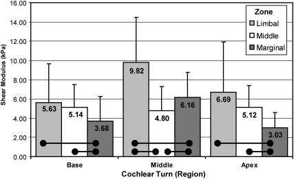
It is significant that the radial TM shear modulus gradient largely follows the gradient of type A fibril density measured in the mammalian TM (Vater and Kössl, 1996; Weaver and Schweitzer, 1994). Weaver and Schweitzer reported an increase in fibril concentration in the limbal zone (corresponding to zone 1 of this study) compared to the marginal zone (zones 4 and 5) in all longitudinal locations studied in the gerbil. Additionally, the authors found a higher concentration of fibrils in the central (radial) zones of the tissue compared to the marginal zones in lower middle and basal cochlear turns, though the difference was not statistically significant at the upper middle turn. Fig. 12 demonstrates similar trends in shear modulus. By discretizing the TM using the criteria established by Lim (1972), we clearly see that the tissue is statistically softer (p < 0.05) in the marginal zone compared to the limbal zone in all cochlear turns, following the fibril density previously reported. We further see that the shear modulus is greater in the middle (radial) zone compared to the marginal zone in the basal and apical turns, but not in the middle cochlear turn. Weaver and Schweitzer, however, also reported a higher concentration of fibrils in the limbal portion of the basal turn compared to the central region of the turn. We did not find a statistically significant difference between the moduli of these limbal and middle zones of the basal turn.
FIGURE 12.
With a more coarse radial discretization of the TM (Lim, 1972), it becomes apparent from these pyramidal-tip data that the tissue is softer in the marginal zone than the limbal zone in all cochlear turns. This corresponds well with the findings of statistically higher collagen fibril density in the limbal zone compared to the marginal zone (Weaver and Schweitzer, 1994). Horizontal bars indicate statistically significant differences (α = 0.05).
Type A fibrils, in contrast to those of type B domains, are believed to be rich in type II collagen (Hasko and Richardson, 1988; Thalmann et al., 1987), which imparts tensile strength and mechanical stability (Thalmann et al., 1987). Hence, regions of reduced type A fibril density should correspond to regions of reduced shear modulus, precisely as we have demonstrated. Although our finding of a relatively large shear modulus in the limbal zone of the middle region does not appear to correspond to a local fibril density increase (Weaver and Schweitzer, 1994), the higher shear modulus may, via an alternate mechanism, lend additional mechanical support where the cross sectional area (Vater and Kössl, 1996) and tissue mass (Thalmann et al., 1987) increase. We shed further light on the correlation between fibril density and shear modulus by considering a surprisingly simple formula (Bird et al., 1977) that relates the shear modulus of an isotropic, entropic spring network to the number density of network segments, n0, the temperature, T, and Boltzmann's constant, k: G = n0kT. Thus, one can determine the elasticity of an isotropic polymeric material knowing only the number of network segments per unit volume and the temperature. The density distribution of type A fibrils, therefore, likely follows, and explains, the distribution of shear moduli in the mammalian TM. In Fig. 8, we present a freeze etch electron micrograph of a guinea pig TM in a region representative of the type A fibril domain. The depth of focus of this image is ∼20 nm. If we were to mentally construct a bounding box representing a volume of 100 nm × 100 nm × 20 nm, and move the box randomly around the image counting the number of network segments within the box, we might count anywhere from 10 to 20 segments. At a temperature of 38°C (311.15 K), each segment in this volume would contribute to the shear modulus
 |
or 0.021 kPa.
Thus, if the tissue were modeled as an isotropic polymer, the formula would predict that type A fibrils would account for a local shear modulus in the range of 0.21–0.42 kPa. We note here that the TM is neither isotropic nor homogeneous; several researchers (Abnet and Freeman, 2000; Zwislocki and Cefaratti, 1989) have reported directionally variant measures of TM stiffness, whereas others (Hasko and Richardson, 1988; Tsuprun and Santi, 1997) report the presence of structurally distinct protein domains. In general, existing models of contact mechanics, upon which we base our calculations of elasticity, assume sample isotropy, and calculations based on these models must be interpreted cautiously. In analyzing contact-mode AFM curves, we approximate representative measures of the tissue elasticity without regard for the local fiber organization or direction. We believe, however, that it is significant that these estimates are within an order of magnitude of the values based on contact mechanics models and that the network model justifies the connection between the type A fibril density and elasticity of the mammalian TM.
In contrast, Ulfendahl et al. (2001) reported observing a “condensed” appearance of the TM in the vicinity of the outer hair cells. This is seemingly contradictory to our results and to those of Weaver and Schweitzer. However, we note here that Ulfendahl made no conclusions about the local density of collagen fibrils or the implications of the distribution of dye on the elasticity of the tissue. Rather, he attributed this dye distribution to structural changes in tissue “density.” This may, in fact, reflect a higher density of “supporting matrix,” rich in noncollagenous type B fibrils. Following Thalmann et al. (1987), we attribute variations in the “resiliency” of the TM elasticity specifically to variations in the distribution of type II collagen seen in type A fibrils.
Energy dissipation
Adapting the arguments of Kolsky (1963), the ratio of energy stored in the membrane at maximal displacement, W, to the energy dissipated, ΔW, in a single cycle of TM oscillation, provides a measure of local shearing efficiency of the TM and can be shown to be directly proportional to the shear modulus. It follows that, in a lumped parameter representation of OC micromechanics, the efficiency of shearing the TM relative to the RL would improve with larger values of G. This lumped parameter assessment agrees well with our FEM calculations (Cai and Chadwick, 2003) of energy dissipation. At high frequencies, we see a strong trend toward greater energy dissipation (lower efficiency) as the tissue softens and less dissipation as the shear modulus increases. The values of calculated energy dissipation for the radially variant TM elasticity generally fall between those calculated using uniformly soft and uniformly hard moduli. The effect appears to be confined to the higher-frequency regions of the TM and to decrease from the base to the apex. For instance, in Table 2 we show the relative energy dissipation calculations (normalized by the energy dissipation calculated using the nonuniform moduli at 500 Hz) at the base (11 kHz and 10 kHz) and the apex (1 kHz and 500 Hz). At the higher frequency, the radially variant shear modulus map reduces the energy dissipation over that calculated for the uniformly soft map by nearly 70% but still provides the protection to the stereocilia afforded by the uniformly soft tissue.
TABLE 2.
Calculated relative energy dissipation in a finite element model of organ of Corti micromechanics
| Shear modulus
|
|||
|---|---|---|---|
| Frequency | Uniformly soft | Radially variant | Uniformly hard |
| 11 kHz | 3046 | 961 | 686 |
| 10 kHz | 1265 | 608 | 505 |
| 1 kHz | 4 | 4 | 4 |
| 500 Hz | 1 | 1 | 1 |
Energy dissipation in the TM, calculated using a FEM of the OC. Values are normalized by the energy dissipation calculated at the apex at 500 Hz. Uniformly soft and uniformly hard refer to minimal and maximal values of TM shear moduli, respectively, measured in the corresponding longitudinal region of the tissue. Radially variant calculations were made using the actual values of elasticity measured in each longitudinal region of the TM.
Compliance matching
On a final note, we verify that the mean value of G measured for the TM is of the same order as a calculated effective shear modulus for the stereocilia bundles: we simply divide a representative stiffness (Strelioff and Flock, 1984) of the hair bundle, 5 × 10⁻³ N/m, by the approximate span (Lim, 1972), w, of a bundle, 5 × 10⁻⁶ m, yielding 1 kPa. This is equivalent to dividing the product of the shear stress, τ, by the shear strain, Δx/b:
 |
where Δx is the bundle displacement, and b is the bundle thickness.
For small motion, we note that our estimate of Geff is independent of Δx, as expected. Compare this with the average values of 4.36 kPa and 1.62 kPa (using unmodified and microsphere-affixed probes, respectively) that we computed for zone 4, where the stereocilia interact with the TM. This is analogous to demonstrating that the TM and stereocilia bundles are compliance matched and validates our determinations of G.
This article provides, to our knowledge, the first detailed examination of the elasticity of the TM. It provides measurements on two different length scales, one more relevant to the deflection of single stereocilia and the other germane to interactions of stereocilia bundles with the TM. Additionally, we present evidence that the tissue elasticity varies radially, generally softening in the neighborhood of the hair cells. We discuss the parallel between the distributions of elasticity and collagen fibrils, and we speculate on the nature and significance of this radial variation. Namely, we suggest that the inhomogeneity in modulus reflects opposing requirements of the tissue; the TM is softer in the region of the hair cells to protect the mechanosensitive hair bundles and less soft elsewhere to increase the energy efficiency of shearing the TM relative to the reticular lamina.
Acknowledgments
The authors thank Dr. Inna Belyantseva for her instruction in TM dissection.
References
- Abnet, C. C., and D. M. Freeman. 2000. Deformations of the isolated mouse tectorial membrane produced by oscillatory forces. Hear. Res. 144:29–46. [DOI] [PubMed] [Google Scholar]
- Bender, C. M., and S. A. Orszag. 1978. Advanced Mathematical Methods for Scientists and Engineers. McGraw-Hill, New York.
- Bilodeau, G. 1992. Regular pyramid punch problem. J. Appl. Mech. 59:519–523. [Google Scholar]
- Bird, R. B., O. Hassager, R. C. Armstrong, and C. F. Curtiss. 1977. Dynamics of Polymeric Liquids, Vol. 2: Kinetic Theory. John Wiley & Sons, New York.
- Cai, H., and R. S. Chadwick. 2003. Radial structure of traveling waves in the inner ear. SIAM J. Appl. Math. 63:1105–1120. [Google Scholar]
- Cai, H. X., B. Shoelson, and R. S. Chadwick. 2004. Evidence of tectorial membrane radial motion in a propagating mode of a complex cochlear model. Proc. Natl. Acad. Sci. USA. 101:6243–6248. [DOI] [PMC free article] [PubMed] [Google Scholar]
- Clark, A. G., S. Glanowski, R. Nielsen, P. D. Thomas, A. Kejariwal, M. A. Todd, D. M. Tanenbaum, D. Civello, F. Lu, B. Murphy, S. Ferriera, G. Wang, X. Zheng, T. J. White, J. J. Sninsky, M. D. Adams, and M. Cargill. 2003. Inferring nonneutral evolution from human-chimp-mouse orthologous gene trios. Science. 302:1960–1963. [DOI] [PubMed] [Google Scholar]
- Clark, J.A., and J. O. Pickles. 1996. The effects of moderate and low levels of acoustic overstimulation on stereocilia and their tip links in the guinea pig. Hear. Res. 99:119–128. [DOI] [PubMed] [Google Scholar]
- Costa, K. D., and F. C. P. Yin. 1999. Analysis of indentation: implications for measuring mechanical properties with atomic force microscopy. J. Biomech. Eng. 121:462–471. [DOI] [PubMed] [Google Scholar]
- Digital Instruments. 1996. AFM/LFM Scanning Probe Microscope Instruction Manual. Digital Instruments/Veeco Metrology Group, Santa Barbara, CA.
- Digital Instruments. 1999. BioScope Instruction Manual. Digital Instruments/Veeco Metrology Group, Santa Barbara, CA.
- Dimitriadis, E. K., F. Horkay, J. Maresca, B. Kachar, and R. S. Chadwick. 2002. Determination of elastic moduli of thin layers of soft material using the atomic force microscope. Biophys. J. 82:2798–2810. [DOI] [PMC free article] [PubMed] [Google Scholar]
- Freeman, D.M., C. C. Abnet, W. Hemmert, B. S. Tsai, and T. F. Weiss. 2003. Dynamic material properties of the tectorial membrane: a summary. Hear. Res. 180:1–10. [DOI] [PubMed] [Google Scholar]
- Grubbs, F. E. 1969. Procedures for detecting outlying observations in samples. Technometrics. 11:1–21. [Google Scholar]
- Hasko, J. A., and G. P. Richardson. 1988. The ultrastructural organization and properties of the mouse tectorial membrane matrix. Hear. Res. 35:21–38. [DOI] [PubMed] [Google Scholar]
- Heim, L. O., M. Kappl, and H. J. Butt. 2004. Tilt of atomic force microscope cantilevers: effect on spring constant and adhesion measurements. Langmuir. 20:2760–2764. [DOI] [PubMed] [Google Scholar]
- Hudspeth, A. J. 1985. The cellular basis of hearing: the biophysics of hair cells. Science. 230:745–752. [DOI] [PubMed] [Google Scholar]
- Kolsky, H. 1963. Stress Waves in Solids. Dover Publications, New York.
- Landau, L. D., and E. M. Lifshitz. 1970. Theory of Elasticity. J. B. Sykes and W. H. Reid, translators. Pergamon Press, Oxford, UK.
- Legan, P. K., V. A. Lukashkina, R. J. Goodyear, M. Kössl, I. J. Russell, and G. P. Richardson. 2000. A targeted deletion in alpha-tectorin reveals that the tectorial membrane is required for the gain and timing of cochlear feedback. Neuron. 28:273–285. [DOI] [PubMed] [Google Scholar]
- Legan, P. K., A. Rau, J. N. Keen, and G. P. Richardson. 1997. The mouse tectorins. Modular matrix proteins of the inner ear homologous to components of the sperm-egg adhesion system. J. Biol. Chem. 272:8791–8801. [DOI] [PubMed] [Google Scholar]
- Lim, D. J. 1972. Fine morphology of the tectorial membrane. Its relationship to the organ of Corti. Arch. Otolaryngol. 96:199–215. [DOI] [PubMed] [Google Scholar]
- McGuirt, W. T., S. D. Prasad, A. J. Griffith, H. P. Kunst, G. E. Green, K. B. Shpargel, C. Runge, C. Huybrechts, R. F. Mueller, E. Lynch, M. C. King, H. G. Brunner, C. W. Cremers, M. Takanosu, S. W. Li, M. Arita, R. Mayne, D. J. Prockop, G. Van Camp, and R. J. Smith, 1999. Mutations in COL11A2 cause non-syndromic hearing loss (DFNA13). Nat. Genet. 23:413–419. [DOI] [PubMed] [Google Scholar]
- Naz, S., F. Alasti, A. Mowjoodi, S. Riazuddin, M. H. Sanati, T. B. Friedman, A. J. Griffith, and E. R. Wilcox. 2003. Distinctive audiometric profile associated with DFNB21 alleles of TECTA. J. Med. Genet. 40:360–363. [DOI] [PMC free article] [PubMed] [Google Scholar]
- Radmacher, M., M. Fritz, and P. K. Hansma. 1995. Imaging soft samples with the atomic-force microscope: gelatin in water and propanol. Biophys. J. 69:264–270. [DOI] [PMC free article] [PubMed] [Google Scholar]
- Simmler, M. C., M. Cohen-Salmon, A. El-Amraoui, L. Guillaud, J. C. Benichou, C. Petit, and J. J. Panthier. 2000. Targeted disruption of otog results in deafness and severe imbalance. Nat. Genet. 24:139–143. [DOI] [PubMed] [Google Scholar]
- Stolz, M., R. Raiteri, A. U. Daniels, M. R. VanLandingham, W. Baschong, and U. Aebi. 2004. Dynamic elastic modulus of porcine articular cartilage determined at two different levels of tissue organization by indentation-type atomic force microscopy. Biophys. J. 86:3269–3283. [DOI] [PMC free article] [PubMed] [Google Scholar]
- Strelioff, D., and A. Flock. 1984. Stiffness of sensory-cell hair bundles in the isolated guinea pig cochlea. Hear. Res. 15:19–28. [DOI] [PubMed] [Google Scholar]
- Thalmann, I., G. Thallinger, E. C. Crouch, T. H. Comegys, N. Barrett, and R. Thalmann. 1987. Composition and supramolecular organization of the tectorial membrane. Laryngoscope. 97:357–367. [PubMed] [Google Scholar]
- Tsuprun, V., and P. Santi. 1997. Ultrastructural organization of proteoglycans and fibrillar matrix of the tectorial membrane. Hear. Res. 110:107–118. [DOI] [PubMed] [Google Scholar]
- Ulfendahl, M., A. Flock, and E. Scarfone. 2001. Structural relationships of the unfixed tectorial membrane. Hear. Res. 151:41–47. [DOI] [PubMed] [Google Scholar]
- Vater, M., and M. Kössl. 1996. Further studies on the mechanics of the cochlear partition in the mustached bat. I. Ultrastructural observations on the tectorial membrane and its attachments. Hear. Res. 94:63–77. [DOI] [PubMed] [Google Scholar]
- Vinckier, A., and G. Semenza. 1998. Measuring elasticity of biological materials by atomic force microscopy. FEBS. Lett. 430:12–16. [DOI] [PubMed] [Google Scholar]
- Weaver, S. P., and L. Schweitzer. 1994. A radial gradient of fibril density in the gerbil tectorial membrane. Hear. Res. 76:1–6. [DOI] [PubMed] [Google Scholar]
- Zwislocki, J. J. 1979. Tectorial membrane: a possible sharpening effect on the frequency analysis in the cochlea. Acta Otolaryngol. 87:267–9. [DOI] [PubMed] [Google Scholar]
- Zwislocki, J. J., and L. K. Cefaratti. 1989. Tectorial membrane. II: stiffness measurements in vivo. Hear. Res. 42:211–227. [DOI] [PubMed] [Google Scholar]


