Abstract
We have cloned a gene encoding a fluorescent protein from a stony coral, Trachyphyllia geoffroyi, which emits green, yellow, and red light. The protein, named Kaede, includes a tripeptide, His-Tyr-Gly, that acts as a green chromophore that can be converted to red. The red fluorescence is comparable in intensity to the green and is stable under usual aerobic conditions. We found that the green-red conversion is highly sensitive to irradiation with UV or violet light (350–400 nm), which excites the protonated form of the chromophore. The excitation lights used to elicit red and green fluorescence do not induce photoconversion. Under a conventional epifluorescence microscope, Kaede protein expressed in HeLa cells turned red in a graded fashion in response to UV illumination; maximal illumination resulted in a 2,000-fold increase in the ratio of red-to-green signal. These color-changing properties provide a simple and powerful technique for regional optical marking. A focused UV pulse creates an instantaneous plane source of red Kaede within the cytosol. The red spot spreads rapidly throughout the cytosol, indicating its free diffusibility in the compartment. The extensive diffusion allows us to delineate a single neuron in a dense culture, where processes originating from many different somata are present. Illumination of a focused UV pulse onto the soma of a Kaede-expressing neuron resulted in filling of all processes with red fluorescence, allowing visualization of contact sites between the red and green neurons of interest.
The mobility of a fluorescent-labeled molecule has been assessed by using a specific photobleaching technique called fluorescence recovery after photobleaching (1). Acquisition of a series of images after photobleaching in a small region of the cell is useful for qualitative description of the diffusion of the fluorescent-labeled molecule. For studying cell lineage, organelle dynamics, and protein trafficking, however, optical marking is preferred; individual cells, organelles, and proteins can be optically labeled with unique colored markers.
The GFP from the luminescent jellyfish Aequorea victoria (Aequorea GFP) allows direct genetic encoding of strong fluorescence and thus is used widely in molecular and cellular biology (2). Many other GFP-like fluorescent proteins have been isolated from fluorescent, but nonbioluminescent, Anthozoa species (3, 4). Three methods of optical marking have become commonplace and are based on photo-induced alteration of the excitation or emission spectrum of certain fluorescent proteins (5–7), such as WT Aequorea GFP and DsRed, a GFP-like fluorescent protein. Some limitations of these methods, however, have been recognized, including dimness and instability of the photoconverted product and the unavailability of simple, efficient, or specific illumination for marking.
In this study, we have cloned a cDNA encoding a fluorescent protein from the stony coral Trachyphyllia geoffroyi. The protein emits bright green fluorescence after synthesis, but changes efficiently to a bright and stable red fluorescence on irradiation with UV or violet light. In this article, we describe examples demonstrating the utility of this marker, especially for cell labeling.
Materials and Methods
cDNA Cloning and Gene Construction.
A BamHI–HindIII fragment encompassing the multicloning site of pFastBac1 (GIBCO/BRL) was inserted into the BamHI/HindIII sites of pRSETB (Invitrogen), yielding pRSET-FastBac, in which an EcoRI site is located closer to the promoter than a NotI site. The stony coral T. geoffroyi was purchased from an aquarium shop. Whole tissue was ground down with a MultiBeads Shocker (Yasui Kikai, Osaka), and total RNA was isolated by following the single-step guanidinium method (8). mRNA was purified by using an Oligo-Tex kit (Roche Diagnostics). cDNA was synthesized with an EcoRI site at the 5′ end and a NotI site at the 3′ end by using a Directional Cloning Tool Kit (Amersham Pharmacia). Ligation of the cDNAs into an EcoRI/NotI-cleaved pRSET-FastBac plasmid produced a directional cDNA library in a prokaryotic expression vector. The library was transformed into the Escherichia coli strain JM109 (DE3). Colonies were screened for fluorescence by using a UV illuminator (365 nm) or our homemade fluorescence analyzing system (9). The cDNA of the coding region of Kaede (no. 9) was amplified by using primers containing 5′ BamHI and 3′ EcoRI sites. The restricted product was cloned in-frame into the BamHI/EcoRI sites of pRSETB for bacterial expression. The 5′ end of the Kaede gene was modified by PCR to have a Kozak consensus sequence (CCACCATG) after the BamHI site. The BamHI/EcoRI fragment was subcloned in the mammalian expression vector pcDNA3 (Invitrogen).
Protein Expression, in Vitro Spectroscopy, pH Titrations, SDS/PAGE, and Multiangle Light Scattering (MALS).
Proteins were expressed in E. coli, purified, and spectroscopically characterized as described (10). The quantum yields of green and red Kaede were determined in comparison to fluorescein (0.91). For calculation of molar extinction coefficients, protein concentrations were measured by using a Bradford assay kit (Bio-Rad) with BSA as the standard. pH titrations were performed as described (11). SDS/PAGE analyses routinely used 15% polyacrylamide gels. MALS was measured with a multiangle light photometer (DAWN, Wyatt, Santa Barbara, CA) connected to a Shodex HPLC system (Showa Denko, Tokyo) on which size exclusion columns (tandem connection of KW-804 and KW-802.5, Showa Denko) were installed. C-terminal His-tagged Kaede was expressed in E. coli by using a pET23b vector (Novagen), and the purified protein was analyzed.
Dissociation Culture of Hippocampal Neurons.
Primary neurons were prepared from Wistar rat embryos (embryonic day 17–18) as described (12, 13). Calcium phosphate precipitation was used to transfect the neurons.
Imaging.
HeLa cells were grown on a 35-mm glass-bottom dish in Dulbecco's modified Eagle's medium containing 10% FBS. Cells were imaged 2–5 days after cDNA transfection with lipofectin (GIBCO/BRL). Cells were imaged on an inverted microscope (Olympus IX70) with a standard 75-W xenon lamp and a ×40 objective lens (Uapo/340, numerical aperture 1.35). Interference filters (excitation and emission filters) contained in wheels were automated by using Lambda 10-2 hardware (Sutter Instruments, Novato, CA). The filter-switching time was set to 50 ms. Emitted light was captured by a cooled charge-coupled device camera (Cool Snap HQ, Roper Scientific, Tucson, AZ). The whole system was controlled by using METAFLUOR 4.5 software (Universal Imaging, Media, PA). Power density of the excitation lights at the cell level was measured with a homemade power meter. Cultured neurons were observed with a confocal microscope based on a Fluoview FV500 scanning unit (Olympus), a diode pumped solid-state laser [Sapphire 488-20 (Coherent Radiation, Palo Alto, CA)], and a green He/Ne laser. Green and red fluorescence signals were captured simultaneously by using the 488- and 543-nm laser lines.
Results and Discussion
Cloning of a Fluorescent Protein That Changes from Green to Red.
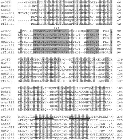
Approximately 150,000 bacterial colonies containing a cDNA library prepared from T. geoffroyi were screened for fluorescence. Two clones were selected that encoded a greenish fluorescent protein. Sequence analysis revealed that the two clones were identical and encoded a fluorescent protein, which was temporarily referred to as no. 9. Although the stony coral exhibits colorful green, yellow, and red fluorescence, no colonies emitting yellow or red light were obtained. Based on an amino acid sequence alignment (Fig. 1), no. 9 has a similar β-can fold to other fluorescent proteins. The crucial amino acid residues that are involved either directly in choromophore formation (Tyr-66, Gly-67) or indirectly, but strongly mediate the process (Arg-96, Glu-222) are conserved in no. 9. The nearest homologue is mcavRFP from the great star coral Montastraea cavernosa (4). Both no. 9 and mcavRFP have a histidine at position 65; aromatic amino acids are not found in this position in any fluorescent proteins except for no. 9, mcavRFP, and rfloRFP, another GFP-like protein from Ricordea florida (4).
Figure 1.
Amino acid sequence (single-letter code) alignment of no. 9 (Kaede) with avGFP (A. victoria GFP) (2), DsRed (3), and the following recently cloned fluorescent proteins (4): mcavGFP, mcavRFP, rfloGFP, and rfloRFP. The numbering is based on Aequorea GFP. In the sequence of avGFP, β-sheet-forming regions are underlined. Residues whose side chains form the interior of the β-can (3) are shaded. Residues responsible for chromophore synthesis are indicated by *.
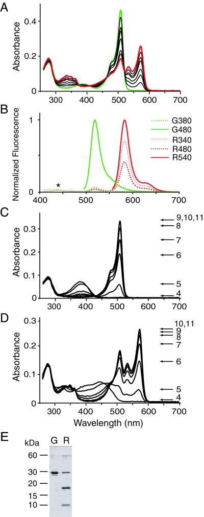
After expression in E. coli, no. 9 protein was purified immediately in 1 night. The absorption spectrum of the purified protein was measured at pH 7.4. (Fig. 2A, green line). It displayed a major absorption wavelength maximum at 508 nm (ɛ = 98,800 M−1⋅cm−1) with a slight shoulder at 475 nm. A minor peak was detected around 380 nm. With decreasing pH, the 508-nm peak amplitude decreased, whereas that of the 380-nm peak concomitantly increased, with an isobestic point at 425 nm (Fig. 2C). This pH dependency indicates that the 380- and 508-nm peaks correspond to the neutral and ionized states, respectively, of the phenolic hydroxyl of the chromophore (2). The apparent pKa was 5.6. On excitation at 480 nm, the protein emitted a bright green fluorescence peaking at 518 nm (Fig. 2B, green line). The fluorescence intensity decreased with acidic pH with the same pKa (= 5.6) as the absorption spectrum (results not shown). It was thus concluded that the fluorescence quantum yield (Φ = 0.80) is not pH-sensitive. Excitation at 380 nm gave a small emission peak at 518 nm.
Figure 2.
Spectra of green and red states of no. 9 (Kaede). (A) Absorption spectra of the unconverted green (green line) and converted red (red line) states. Spectra obtained during the green-red conversion are displayed as thin black lines. (B) G380 and G480: emission spectra of the green state (green line) on excitation at 380 and 480 nm, respectively. R340, R480, and R540: emission spectra of the red state (red line) on excitation at 340, 480, and 540 nm, respectively. The spectra of the green and red states were normalized with the highest values of G480 and R540, respectively. The small peak at 440 nm in G380 was caused by water raman and is indicated by *. (C) pH dependence of the green state absorbance. (D) pH dependence of the red state absorbance. (E) Band patterns of the green (G) and red (R) states of Kaede after SDS/PAGE and Coomassie brilliant blue staining.
We happened to leave one of the protein aliquots on the laboratory bench overnight. The next day, we found that the protein sample on the bench had turned red, whereas the others that were kept in a paper box remained green. Although the sky had been partly cloudy, the red sample had been exposed to sunlight through the south-facing windows. The absorption spectrum of the red protein was measured at pH 7.4 (Fig. 2A, red line). The major absorption peak at 508 nm and minor peak at 380 nm were reduced in size, and new peaks appeared at 572 (ɛ = 60,400 M−1⋅cm−1), 533, and 348 nm. These peaks reflect the ionized state of the chromophore; they were augmented equally with increasing pH, with a pKa of 5.7. When excited at 480 nm, the protein showed an emission maximum at 582 nm with a shoulder at 627 nm (Fig. 2B, red line) in addition to the 518-nm peak. The emissions at 582 and 627 nm were also pH-sensitive, with a pKa of 5.6 (results not shown), indicating that the red fluorescence quantum yield (Φ = 0.33) is also pH-resistant.
To verify this serendipitous observation, we put a green sample of no. 9 (0.2 μg/μl) in a cuvette (1 ml) over a UV illuminator emitting 365-nm light (1,820 μW/cm2) and found that the sample turned red within several minutes. During the color change, the absorption spectra were measured intermittently and are indicated in Fig. 2A by black thin lines. Isobestic points were detected at 376, 405, 464, and 519 nm. At this point, no. 9 was renamed Kaede, which means maple leaf in Japanese. The photoconversion was irreversible; neither dark exposure nor strong illumination at 570 nm could restore the green fluorescence (data not shown). A similar green-to-red color change had been noticed in both mcavRFP and rfloRFP (4), but it was described as a time-dependent maturation of the chromophore. Because all three fluorescent proteins share a histidine at position 65, the imidazole ring may be involved in the extension of the conjugated π-system, resulting in the photoconversion to red. In fact, replacement of the histidine with phenylalanine or glutamine resulted in a GFP that did not exhibit red photoconversion (data not shown).
For the SDS/PAGE analysis, we incubated unconverted and converted Kaede proteins at 95°C for 5 min. Whereas the unconverted Kaede showed a single band at 28 kDa, most of the converted Kaede distributed between two bands at 18 and 10 kDa (Fig. 2E). This fragmentation is similar to that observed in DsRed (14) and a purple chromoprotein, asFP595 (15), and may be critical for the green-to-red conversion of Kaede.
Tetramer Formation of Kaede.
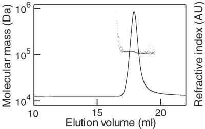
We determined the absolute molecular mass of Kaede by using MALS. C-terminal His-tagged Kaede protein was applied to two size-exclusion columns that were connected in tandem, and the eluate was analyzed by using a MALS photometer (Fig. 3). The absolute molecular mass was calculated to be 116.0 kDa. This value was 4.33 times larger than that (26.75 kDa) deduced from the primary structure of the protein. It was therefore concluded that Kaede forms a homotetrameric complex, like DsRed or drFP583, a commercially available red fluorescent protein (3, 4).
Figure 3.
Determination of the absolute molecular mass of Kaede protein. The molecular mass (dots) was calculated from MALS data and overlaid on the refractive index chromatogram (solid line).
Excitation of Protonated Chromophore for Photoconversion.
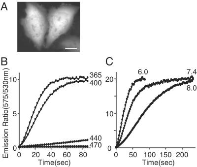
By analogy to the photoconversion of WT Aequorea GFP from the neutral to the ionized form (2), we hypothesized that the Kaede photoconversion occurs on excitation of the protonated form of the chromophore by irradiation with UV or violet light. To test this hypothesis, we investigated the dependency of the photoconversion on the wavelength of the illumination light and on pH. When expressed in HeLa cells, Kaede protein was distributed in the cytosol and nucleus (Fig. 4A). Green and red fluorescence images were captured by alternating between 510WB40 and 575ALP emission filters, respectively, with reduced illumination at 470 nm. In the intervals, the whole area of the cell was illuminated continuously to induce photoconversion. First, the wavelength of photoconverting light was varied (Fig. 4B). With illumination at 365 and 400 nm, photoconversion occurred promptly; the green fluorescence dropped immediately, whereas red increased concomitantly. The ratio of red to green (R/G) increased more than 100-fold, reaching a maximum within a minute. With illumination at 440 nm, photoconversion was significantly slower. Illumination at 470 nm failed to photoconvert; the green fluorescence decreased slowly, but there was no concomitant increase in red fluorescence. Considering the power density of the illumination lights (see the legend for Fig. 4B), it appeared that the photoconversion resulted from the excitation of the protonated state by irradiation around 380 nm. Next, the photoconversion rate was assessed at different pHs under the same optical conditions with illumination at 380 nm. The photoconversion was facilitated by acidic pH (Fig. 4C), which favors the protonated form (Fig. 2C). These results strongly support the involvement of the protonated chromophore in the photoconversion.
Figure 4.
Parameters that influence the photoconversion of Kaede expressed in HeLa cells. (A) A fluorescence micrograph of HeLa cells expressing green Kaede. (Scale bar: 20 μm.) (B) Time courses of R/G emission ratio with continuous illumination at 365 nm (365WB50; 3.5 W/cm2), 400 nm (400DF15; 1.6 W/cm2), 440 nm (440DF20; 2.8 W/cm2), and 470 nm (470DF35; 4.3 W/cm2). To observe fluorescence, cells were excited at 470 nm. A 1.6-W/cm2 beam of ≈400-nm light gave 90% of maximal photoconversion in 50 s; its quantum yield (19) was calculated to be 2.4 × 10⁻⁴. (C) Time courses of R/G emission ratio with continuous illumination at 380 nm (380HT15; 0.86 W/cm2), when intracellular pH was clamped to 6.0, 7.4, and 8.0. Cells were soaked in the pH buffers in the presence of 20 μM monensin and 20 μM nigericin.
Optical Marking Using Kaede.
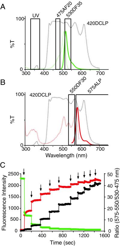
Because the photoconverted Kaede requires the absorption of green light (λ = 550–600 nm) for emission of bright red fluorescence, the appearance of the fluorescence through a long-pass emission filter (575ALP) was monitored during direct excitation via an excitation filter (550DF30). In parallel, the decay of the green fluorescence was monitored by using a 470DF30 excitation filter and a 530DF35 emission filter. The dual-excitation and dual-emission ratiometric measurement was expected to give bigger change in the R/G ratio. The red and green fluorescence images were alternately captured by using a 420DCLP dichroic mirror as the highly transmissive reflector (16). The interference filters used for the green and red fluorescence are shown in Fig. 5 A and B, respectively. This configuration eliminated the need for exchanging dichroic mirrors, which minimizes the time difference between the two images. Furthermore, the excitation lights for image acquisition were moderately attenuated without neutral density filters, while UV or violet light for the photoconversion was maximally reflected to cell samples. In addition, another illuminator with a 75-W xenon lamp was coupled into the optical axis through a dual port containing a UV-reflecting dichroic mirror. This branching illuminator had holders for a pinhole in the plane of the field iris and a 360DF40 filter. By using the two light sources, it was possible to give the UV pulses for photoconversion during image acquisition.
Figure 5.
Dual-excitation and dual-emission ratiometric measurement of the photoconversion of Kaede. (A) Excitation (green dotted line) and emission (green solid line) spectra of green Kaede and the interference filters used for photoconversion or observation of green fluorescence. (B) Excitation (red dotted line) and emission (red solid line) spectra of red Kaede and the interference filters used for observation of red fluorescence. Band-pass and long-pass filters are indicated by boxes, with the transmission curve of the dichroic mirror 420DCLP (dotted line) in A and B. (C) Time course of green (green circles) and red (red circles) Kaede fluorescence intensity in HeLa cells and the R/G fluorescence signal ratio (black circles). Arrows indicate the 1-s UV pulses.
Kaede proteins distributed in HeLa cells were imaged to observe photoconversion (Fig. 5C). Cells were illuminated intermittently for 1 s with UV light. The power density at the cell level was 1.3 W/cm2. After the first 1-s pulse of UV light, the red signal increased immediately, and the green decreased, resulting in a 63-fold increase in the R/G ratio, from 0.019 to 1.2. Subsequent UV pulses resulted in incremental increases in the ratio, which gradually approached a saturating level. After nine UV pulses, the R/G ratio of the fully photoconverted proteins reached 41.0, about 2,000-fold more than the original value (0.019). It should be noted that after each UV pulse, both the red and green signals and their ratio were stable, suggesting that the photoconverted isoform is stable within the cells. Because a color change is being photo-induced, even partial photoconversion would be useful for efficient marking of cells and subcellular structures. This is an advantage of this technique over fluorescence recovery after photobleaching, where full photobleaching in a region is necessary, requiring relatively long and intense illumination. In the above experiment, for example, the first 1-s UV pulse would generate sufficient red signal to achieve regional marking with considerable contrast.
Measurement of Diffusional Mobility of Kaede in the Cytosol.
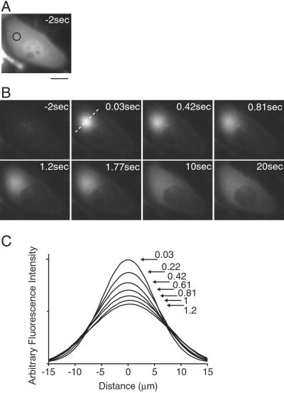
A pinhole was placed in the plane of the field iris in the UV illuminator to focus the UV pulse on a spot 10 μm in diameter. The point of light was focused within the cytosolic compartment of a HeLa cell expressing Kaede protein (Fig. 6A). Red fluorescence images were taken about every 0.2 s; 0.03 s after the 1-s UV pulse, a spot of red fluorescence emerged. The spot spread concentrically until it reached the nuclear envelope at 1.2 s (Fig. 6B). The fluorescence intensity-distance curves for the red fluorescence peak across the spot are shown in Fig. 6C. Each curve was fit by a Gaussian distribution (5). From the relationships between the time and the square of the peak radius, the diffusion coefficient of Kaede in the cytosol was calculated to be 29 μm2/s. This value is comparable to that of the freely diffusible GFP mutant, cycle 3 (43 μm2/s) (5), suggesting that the homotetrameric complex of Kaede has a hydrophilic surface and minimal binding partners inside cells. After 20 s, the red fluorescence spread over the entire cytosol, but was excluded from the nucleus. The rapid diffusion in the cytosol would enable the optical delineation of the entire region of a cell with a complex geometry, although the equilibrium of the protein between the cytosolic and nuclear compartments proved to be very slow.
Figure 6.
Rapid diffusion of red Kaede within the cytosol. (A) A fluorescence micrograph of a HeLa cell expressing green Kaede protein. The UV-exposed point is indicated by an open circle. (Scale bar: 20 μm.) (B) Representative images showing the emergence and spreading of the red fluorescence. Time after the end of the UV pulse is indicated in each picture. Images in A and B were taken by using the configuration shown in Fig. 4 A and B. (C) A series of fluorescence intensity-distance curves after the UV pulse. The fluorescence intensity along the line shown in the image at 0.03 s in B was analyzed. Each curve was fit by a Gaussian and is displayed. Time after the end of the UV pulse is indicated in the graph.
Visualization of Individual Neurons.
In a dense culture containing neurons and glial cells, it is hard to delineate individual neurons, because they extend long and thin processes that become entangled with those belonging to other cells. When cultured neurons are labeled with fluorescent proteins by gene transfection or viral infection, fluorescent neurons are packed too densely to be identified separately. It is thus helpful to have a means of visualizing the dendrites and axons of individual neurons of interest when analyzing a network composed of multiple neurons. Such visualization has been achieved by a conventional but laborious technique, filling neurons with Lucifer yellow or sulforhodamine.
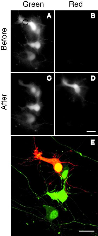
Dissociated hippocampal neurons were cultured on a monolayer feeder of astrocytes. Transfection with Kaede cDNA produced many green neurons that were observed to be entangled with each other (Fig. 7A). No signal was detected through the red channel (Fig. 7B). A focused UV pulse was given to the cytosolic portion (indicated by a circle in Fig. 7A) of a cell soma for 10 s. The photoconverted Kaede protein was observed to spread over the entire cell, including its dendrites and axon, within a few minutes. Fig. 7 C and D shows images 3 min after the UV pulse, indicating that the entire region of the neuron turned red. As in Fig. 6, the nucleus did not fill efficiently with red photoconverted Kaede protein. Next, the neurons were immediately observed with a confocal microscope by using the 488- and 543-nm laser lines for the green and red signals, respectively. A merged image (Fig. 7E) clearly shows the outline of the reddened neuron and the contact sites with adjacent green neurons. It is also possible to label more than two neurons with different colors by UV irradiating with different duration times. This technique will help disentangle the complex networks established in a dense culture.
Figure 7.
Visualization of an individual neuron in a hippocampal primary culture. (A and B) One day after transfection with Kaede cDNA, green and red fluorescence images were taken by using the configurations shown in Fig. 5 A and B, respectively. A spot in the cytosolic portion (indicated by a circle) of a neuron was UV-pulsed for 10 s. (C and D) Green and red fluorescence images 3 min after the UV pulse. (E) The red neuron and adjacent green neurons were imaged simultaneously by using confocal microscopy with 488/543-nm excitation and merged. A series of confocal images along z axis are projected. (Scale bar: 20 μm.)
Optical Marking Techniques.
To date, three approaches have been used for regional marking of fluorescent proteins. They are based on the photo-induced alteration of excitation or emission spectra of a fluorophore (5–7).
First, WT GFP from A. victoria absorbs predominantly at 398 nm. Illumination with violet light (≈400 nm) transforms the neutral phenolic chromophore absorbing at 398 nm into an ionic species absorbing at 483 nm (2). This photoconversion is accompanied by decarboxylation of Glu-222 (17). After strong irradiation with violet light, the relative intensities of green fluorescence emitted when excited with 398 and 483 nm light can be monitored to track the phototransformed WT GFP. Although such ratiometric observation is quantitative, dual-excitation measurements are not generally amenable to laser-scanning confocal microscopy. Also, due to the use of 398-nm light for observation, there is a concern that photoconversion may occur during image acquisition.
Second, a number of GFPs undergo photoconversion to a red fluorescent species (6). The red fluorescence, however, is extremely dim and extinguishes quickly under normal aerobic conditions.
Third, Marchant et al. (7) reported that three-photon excitation (< 760 nm) selectively bleaches the mature, red-emitting form of the red fluorescent protein (DsRed, CLONTECH), thereby enhancing emission from the immature, green form through reduction of fluorescence resonance energy transfer (7). The “greening” effect appears to be complex, because it depends on the maturation efficiency of DsRed. Although multiphoton excitation can localize the photoconversion in three dimensions within a minute region, it requires special equipment, including a femto-second Ti:Sapphire laser.
In contrast, optical marking using Kaede has several advantages. First, the red fluorescence emitted from the photoconverted Kaede is bright and stable for months without requiring rigorous anaerobic conditions. The red state is comparable to the green in terms of brightness and stability. Because unconverted Kaede emits very little red fluorescence, the appearance of red signals provides appreciable contrast. Complete photoconversion results in a more than 2,000-fold increase in the R/G fluorescence ratio. Second, illumination lights for observation and photoconversion can be separated completely. Image acquisition of the green and red fluorescence is done with excitation by using blue (≈480 nm) light alone or blue (≈480 nm) and green (≈550 nm) lights. Neither wavelength induces photoconversion.
In this study, optical marking using Kaede was performed by using a conventional wide-field microscope, which demonstrates the broad and ready applicability of this technique. We have also extended this technique to laser scanning confocal microscopy. In this system, Kaede can be photoconverted by using a violet laser diode (405 nm) or a femtosecond pulsed laser (results not shown). These lasers should enable more efficient and spatially restricted optical marking. Although Kaede exhibited free mobility within the cytosolic compartment, it also showed a weak tendency to form aggregates when fused to certain other proteins, probably due to its obligate tetramerization, as is seen in the WT DsRed. Recently, Campbell et al. (18) have converted DsRed into a monomeric red fluorescent protein (mRFP1) in a stepwise fashion. This work demonstrates the possibility of converting other oligomeric fluorescent proteins into monomers. Similar semirational approaches based on the homology between Kaede and DsRed (Fig. 1) are being explored to develop a monomeric Kaede. This will ultimately be used for optical marking of Kaede-fused proteins to monitor protein trafficking.
Finally, our present study not only demonstrates the benefits of a cloned fluorescent protein, but assesses the molecular mechanisms for the color variation occurring within an individual T. geoffroyi. When exposed to sunlight, the tentacles and disk would turn a shade of red in proportion to the degree of Kaede photoconversion. Then, they would revert to green as Kaede is added. This mechanism may be responsible for the variety of color in stony corals.
Acknowledgments
We thank Dr. M. Nakamura for acquisition of MALS data and Dr. S. Karasawa for valuable advice. This work was partly supported by grants from Core Research for Evolutional Science and Technology (CREST) of Japan Science and Technology (JST) and the Japanese Ministry of Education, Science, and Technology.
Abbreviations
- MALS
multiangle light scattering
- R/G
red to green
Footnotes
This paper was submitted directly (Track II) to the PNAS office.
Data deposition: The sequence reported in this paper has been deposited in the GenBank database (accession no. AB085641).
References
- 1.Lippincott-Schwartz J, Snap E, Kenworthy A. Nat Rev Mol Cell Biol. 2001;2:444–456. doi: 10.1038/35073068. [DOI] [PubMed] [Google Scholar]
- 2.Tsien R Y. Annu Rev Biochem. 1998;67:509–544. doi: 10.1146/annurev.biochem.67.1.509. [DOI] [PubMed] [Google Scholar]
- 3.Matz M V, Fradokov A F, Labas Y A, Savitsky A P, Zaraisky A G, Markelov M L, Lukyanov S A. Nat Biotechnol. 1999;17:969–973. doi: 10.1038/13657. [DOI] [PubMed] [Google Scholar]
- 4.Labas Y A, Gurskaya N G, Yanushevich Y G, Fradkov A F, Lukyanov K A, Lukyanov S A, Matz M V. Proc Natl Acad Sci USA. 2002;99:4256–4261. doi: 10.1073/pnas.062552299. [DOI] [PMC free article] [PubMed] [Google Scholar]
- 5.Yokoe H, Meyer T. Nat Biotechnol. 1996;14:1252–1256. doi: 10.1038/nbt1096-1252. [DOI] [PubMed] [Google Scholar]
- 6.Elowitz M B, Surette M G, Worf P-E, Stock J, Leiber S. Curr Biol. 1997;7:809–812. doi: 10.1016/s0960-9822(06)00342-3. [DOI] [PubMed] [Google Scholar]
- 7.Marchant J S, Stutzmann G E, Leissring M A, LaFerla F M, Parker I. Nat Biotechnol. 2001;19:645–649. doi: 10.1038/90249. [DOI] [PubMed] [Google Scholar]
- 8.Chomczynski P, Sacchi N. Anal Biochem. 1987;162:156–159. doi: 10.1006/abio.1987.9999. [DOI] [PubMed] [Google Scholar]
- 9.Sawano A, Miyawaki A. Nucleic Acids Res. 2000;28:E78. doi: 10.1093/nar/28.16.e78. [DOI] [PMC free article] [PubMed] [Google Scholar]
- 10.Miyawaki A, Llopis J, Heim R, McCaffery J M, Adams J A, Ikura M, Tsien R Y. Nature (London) 1997;388:882–887. doi: 10.1038/42264. [DOI] [PubMed] [Google Scholar]
- 11.Nagai T, Sawano A, Park E S, Miyawaki A. Proc Natl Acad Sci USA. 2001;98:3197–3202. doi: 10.1073/pnas.051636098. [DOI] [PMC free article] [PubMed] [Google Scholar]
- 12.Kossel A H, Williams C V, Schweizer M, Kater S B. J Neurosci. 1997;17:6314–6324. doi: 10.1523/JNEUROSCI.17-16-06314.1997. [DOI] [PMC free article] [PubMed] [Google Scholar]
- 13.Kakimura Y, Hama H, Sugiyama F, Goto K, Murakami K, Fukamizu A. Neurosci Lett. 1997;232:167–170. doi: 10.1016/s0304-3940(97)00605-8. [DOI] [PubMed] [Google Scholar]
- 14.Gross L A, Baird G S, Hoffman R C, Baldridge K K, Tsien R Y. Proc Natl Acad Sci USA. 2000;97:11990–11005. doi: 10.1073/pnas.97.22.11990. [DOI] [PMC free article] [PubMed] [Google Scholar]
- 15.Martynov V I, Savitsky A P, Martynova N Y, Savitsky P A, Lukyanov K A, Lukyanov S A. J Biol Chem. 2001;276:21012–21016. doi: 10.1074/jbc.M100500200. [DOI] [PubMed] [Google Scholar]
- 16.Sawano A, Hama H, Saito N, Miyawaki A. Biophys J. 2002;82:1076–1085. doi: 10.1016/S0006-3495(02)75467-2. [DOI] [PMC free article] [PubMed] [Google Scholar]
- 17.van Thor J J, Gensch T, Hellingwerf K J, Johnson L N. Nat Struct Biol. 2002;9:37–41. doi: 10.1038/nsb739. [DOI] [PubMed] [Google Scholar]
- 18.Campbell R E, Tour O, Palmer A E, Steinbach P A, Baird G S, Zacharias D A, Tsien R Y. Proc Natl Acad Sci USA. 2002;99:7877–7882. doi: 10.1073/pnas.082243699. [DOI] [PMC free article] [PubMed] [Google Scholar]
- 19.Adams S R, Kao J P Y, Grynkiewicz G, Minta A, Tsien R Y. J Am Chem Soc. 1988;110:3212–3220. [Google Scholar]


