Abstract
This study reports the design, realization, and characterization of a multi-pole magnetic tweezers that enables us to maneuver small magnetic probes inside living cells. So far, magnetic tweezers can be divided into two categories: I), tweezers that allow the exertion of high forces but consist of only one or two poles and therefore are capable of only exerting forces in one direction; and II), tweezers that consist of multiple poles and allow exertion of forces in multiple directions but at very low forces. The magnetic tweezers described here combines both aspects in a single apparatus: high forces in a controllable direction. To this end, micron scale magnetic structures are fabricated using cleanroom technologies. With these tweezers, magnetic flux gradients of ∇B = 8 × 10³ T m−1 can be achieved over the dimensions of a single cell. This allows exertion of forces up to 12 pN on paramagnetic probes with a diameter of 350 nm, enabling us to maneuver them through the cytoplasm of a living cell. It is expected that with the current tweezers, picoNewton forces can be exerted on beads as small as 100 nm.
INTRODUCTION
Biological sciences are entering a completely new phase. Genomics, proteomics, and metabolomics have provided us with a long list of components and physical interactions and chemical reactions that occur in the living cell. We are now at the very beginning of an era in which we have to integrate this knowledge in terms of networks of molecular processes. Such networks are responsible for fundamental processes, such as the orchestration of gene expression, intermediary metabolism, signal transduction, and cell cycle control, processes that are precisely controlled in time and space. These interaction networks constitute the molecular basis of life. At the same time, importantly, they are the key to understanding the pathological state of cells, for instance during tumorigenesis, and for the rational design of drugs and therapies.
A variety of techniques has been developed to investigate the localization, dynamics, and interactions of molecules inside living cells, for instance, the use of green fluorescent protein technology in combination with live cell microscopy, fluorescence recovery after photobleaching, and fluorescence resonance energy transfer (Wouters et al., 2001). These and other techniques are giving detailed insight into molecular processes in living cells. However, these approaches have the limitation that they only passively follow the processes in time and space in cells and tissues.
A number of techniques have been developed for nanomanipulation of biological systems and single molecule research. Techniques such as atomic force microscopy (Viani et al., 1999), optical tweezers (Svoboda et al., 1993), and to a limited extend magnetic tweezers (Strick et al., 1996) are widely used to study the behavior of individual macromolecules. To this end, molecules are often attached to micron-sized latex and/or magnetic beads, allowing the nanometer-accurate movement and positioning of the molecule and the measurement and exertion of forces on these molecules in the biologically relevant picoNewton (pN) range. Experiments have addressed the dynamics of various biomolecular systems, including the movement of a single RNA-polymerase along a DNA molecule (Davenport et al., 2000), kinesin movement along microtubules (Howard et al., 1989), and the analysis of chromatin structure (Pope et al., 2002). However, the limitation of these techniques is that they rarely allow the analysis of molecular systems inside live cells or tissues. Requirements for techniques that do allow for nanomanipulation inside cells are as follows: I), the force probes used should be small (≪1 μm); II), the forces that can be exerted on the probe should be in the relevant biological range of at least a few pN; and III), the forces should be controllable in amplitude and direction to maneuver the probe to the site of interest. The use of magnetic forces may be a good candidate to achieve these requirements. Present-day application of magnetic tweezers to live cells relies mostly on microrheology (Bausch et al., 1999). It has been shown that large forces can be exerted on magnetic beads that have been introduced in cells (Hosu et al., 2003). However, these magnetic tweezers consists of either one or two poles and therefore do not easily allow the manipulation of magnetic probes in different directions. In principle, one could maneuver the pole(s) with respect to the bead such that the force on the bead can be changed in direction. A major drawback of such an approach is that it is technically very difficult to obtain the required speed and accuracy for the repositioning of the pole(s) to allow accurate manipulation. Other, more practical designs have been realized that do consist of multiple magnetic poles and therefore allow for two-dimensional (2D) or three-dimensional (3D) manipulation but have the associated drawback of low forces (Amblard et al., 1996; Gosse and Croquette, 2002; Huang et al., 2002; Sacconi et al., 2001). In this article, a new type of magnetic tweezers is described that relies on micron scale magnetic pole structures that can be positioned close to a living cell. It will be shown that in this way it is possible to combine both high forces with the capability of real 2D manipulation of the magnetic probe inside living cells. These magnetic tweezers can potentially be used for nanomanipulation of molecular systems inside living cells. The technique of optical tweezers also has the advantage of full 3D manipulation and has also been used to manipulate beads inside cells or on cell surfaces for, e.g., microrheology (Caspi et al., 2002; Laurent et al., 2002) or molecular manipulation (Peters et al., 1999).The advantages of magnetic tweezers become evident especially when exploring intracellular properties. Optical tweezers exert forces on microscopic objects that have a refractive index contrast with its surroundings. Since there is a myriad of such objects inside a cell, optical tweezers cannot always selectively operate in the intracellular environment. Furthermore, the relatively high optical intensities required can damage the sample (Neumann et al., 1999).
MATERIAL AND METHODS
Magnetic tweezers design and fabrication
A major design goal of the current magnetic tweezers is to achieve high forces on relatively small magnetic beads in combination with the possibility to control the direction of the force (in 2D). The magnetic force Fm on a magnetic bead with a magnetization m is given by Eq. 1:
 |
(1) |
where B denotes the magnetic flux density. The amplitude of the force thus depends on the achievable field gradient and on the magnetization of the bead. The latter is limited by material properties of the bead due to saturation of the magnetization at high magnetic fields. Choosing proper materials (e.g., iron or cobalt-iron alloys) that have a high saturation magnetization and a high magnetic susceptibility is required. Further increasing the force relies on the optimization of the field gradient. In general, a field gradient is created by using a pole that conducts magnetic flux into a sharp tip. The high flux density at the pole tip strongly diverts outside the pole tip, resulting in a high field gradient. The maximum achievable field gradient depends on both the saturation magnetization of the pole material and the geometry of the pole tips. Considering a parabolic shaped pole tip, an analytical expression can be derived for the field gradient at a given distance r from the pole defined as in Eq. 2 (see Appendix A):
 |
(2) |
In Fig. 1, this Eq. 2 is evaluated for different tip radii. Clearly, the maximum field gradient achievable scales with the distance from the tip, r, as ∇B ∼ r−1. However, the range over which the gradient exists is strongly reduced in the limit of small tip radii. Considering the goal to use the magnetic tweezers for live cell applications, the field gradient should be optimized for distances of at least the order of the dimensions of a single cell. This requires tip diameters in the order of micrometers. To be able to control the direction of the force, the magnetic tweezers should consist of at least three magnetic poles that can be operated individually.
FIGURE 1.
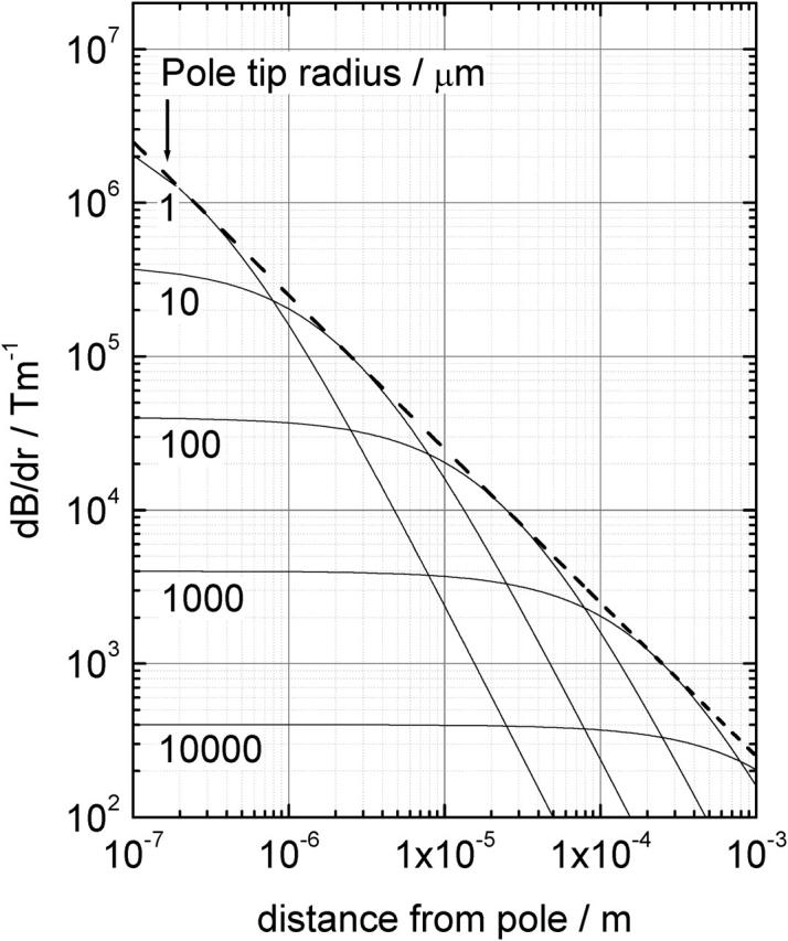
Calculated gradients in the magnetic flux density for single parabolic shaped magnetic poles plotted as a function of the distance to the pole tip for different pole tip radii. The dashed line corresponds to maximum achievable gradient at a given distance.
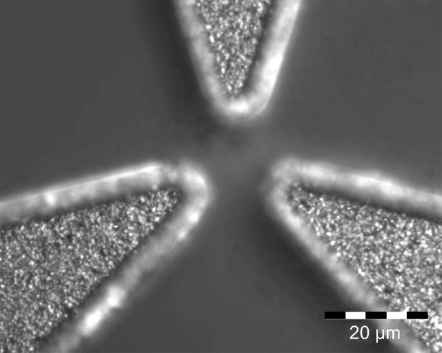
The spatial geometry of the magnetic poles was optimized using finite element software (FEMLAB, COMSOL, Stockholm, Sweden). Both four- and three-pole geometries were considered. The general design of the magnetic tweezers (consisting of four poles) is shown in Fig. 2. Four electric coils are used to generate flux either toward or away from the poles. Due to their small dimensions, the poles themselves are fabricated using cleanroom technology as described elsewhere (deVries et al., 2004). In brief, cobalt is electroplated onto glass substrates into a predefined pattern defined by a photoresist layer. In this way, cobalt poles of well-defined shape and thickness (up to ∼8 micron) can be fabricated. Cobalt was chosen for its relatively high saturation magnetization of 1.8 T (Watson, 1980) and its resistance to aqueous environments. An example of a three-pole magnetic structure is shown in Fig. 3.
FIGURE 2.
Layout of a four-pole magnetic tweezers. A macroscopic magnetic yoke accommodates four electric coils that are used to generate the magnetic flux. The coils can be individually addressed to control the amplitude and the direction of the magnetic flux gradient at the center position. In this figure, the resulting gradient and thus the force is directed to the leftmost pole.
FIGURE 3.
Microscope image of the pole tips of a three-pole magnetic tweezers. Clearly visible are the granular structure of the cobalt. The edges of the pole tips are not imaged sharply because they are slightly higher than the central part of the poles.
The whole magnetic tweezers system is mounted on an optical microscope (IMT-2 Olympus, Tokyo, Japan) equipped with a long working distance objective lens (LWD CDPLAN 40×, 0.55 NA, Olympus). Movements of the bead inside the cell are recorded with a video camera (with a frame rate of 25 Hz) and stored on tape for later analysis. The recorded movies are digitized, and bead positions and displacements are extracted from the individual frames by custom software. The standard deviation in the determined bead position was estimated to be 0.1 pixel corresponding to 14 nm as determined by analysis of images of a bead that was glued to a glass substrate.
Force calibration and characterization of the tweezers
A micropipette with known spring constant and having a magnetic bead at the tip is used to measure the field gradient produced by the magnetic tweezers. To this end, a magnetic bead (DYNABEADS M280, Dynal, Oslo, Norway; volume magnetization of 11.5 kA m−1) is attached (using two-component epoxy glue) to the end of the pipette, and this construct is suspended perpendicular to the poles. The bead displacement Δx due to the applied magnetic force Fm is recorded using video microscopy. The video is analyzed off-line using custom Labview software (National Instruments, Austin, Texas) that tracks the position of the bead with subpixel accuracy. Having calibrated both the magnetic moment mb of the bead (using a vibrating sample magnetometer) and the spring constant of the pipette kp (against a calibrated atomic force microscopy cantilever), the magnetic field gradient is found by Eq. 3:
 |
(3) |
Borosilicate pipettes of 1.2-mm outer diameter and 0.94-mm inner diameters (Harvard Apparatus GC120TF-15, Holliston, MA) were pulled using a Sutter (Novato, CA) P-87 micropipette puller. The stiffness of these pipettes was calibrated against an AFM cantilever with known spring constant. The two types of cantilever used for the calibration (TM Microscopes (Veeco, Woodbury, NY), microlevers tip B and C) have a spring constant of 10 and 20 nN μm−1, respectively. Before use, these cantilevers are recalibrated in an AFM to get an improved accuracy of the spring constant supplied by the manufacturer.
The pipette used for the calibration had a tip diameter of 800 nm, with a final taper of only 1 mm. The micropipette was calibrated against both AFM cantilevers, yielding a spring constant of 0.8 ± 0.1 nN μm−1. The force resolution is limited to ∼10 pN.
The micropipette with magnetic bead was placed between the poles of the magnetic tweezers by means of a micromanipulator. A square current with 33% duty cycle (for the three-pole structure) was supplied to the coils, so that the bead was pulled toward each one of the poles in succession, in this way following a triangular path. The displacement Δx was calculated as the distance from one of the corners of the triangle to the center of the triangle. The recorded bead displacements and derived magnetic forces were determined for different current amplitudes through the coils. Although it is possible to determine the force at any given position within the working area of the magnetic tweezers, measurements were limited mainly to the center part of the tweezers. Slight deviations of several micrometers from this center did not lead to large changes in force, whereas positioning the bead close to the pole tips resulted in snapping of the bead onto the pole tip due to the high forces and preventing an accurate force measurement.
Bead protocol for live cell experiments
Two types of super paramagnetic beads are used: 1.05-μm diameter Dynal ‘MyOne’ (Dynal) magnetic beads and 0.35-μm diameter 47% γ-Fe3O4 beads (Bangs Laboratory, Fischers, IN). Although the beads have a relatively low volume magnetization (28.4 kA m−1 and 65.0 kA m−1, respectively), forces up to 120 pN for the 1.05-μm beads and forces up to 12 pN for the 0.35-μm beads could be exerted, which proved to be enough to induce bead displacements in live cells. The magnetic beads were opsonized using blood serum to promote phagocytosis of the beads by the cells.
Cells
Magnetic beads were introduced into a living cell by phagocytosis. Granulocytes were isolated from fresh blood, using standard density centrifugation protocol from CLB (Central Laboratory Blood transfusion service) at Amsterdam. Beads and cell suspension are then mixed and incubated for 30 min. The cells with embedded beads are then deposited on glass slides treated with poly-L-lysine and left to attach for 30 min for proper adhesion of the cells to the glass slides. Before use, these slides are rinsed with phosphate-buffered saline buffer to remove any nonattached cells and beads.
Experimental procedure for live cell measurements
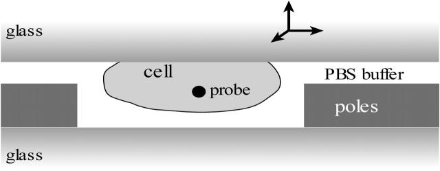
A drop of phosphate-buffered saline buffer medium is placed on the substrate containing the magnetic poles. The substrate with the granulocytes is then positioned face-down on top of the substrate magnetic poles. A sandwich is thus formed, with magnetic poles and cells in between the two glass plates (Fig. 4). The cell substrate is attached to a micromanipulator, which allows selecting a cell containing a single magnetic probe, and positioning the cell between the magnetic poles.
FIGURE 4.
Experimental geometry for live cell measurements. Living cells that contain magnetic beads are deposited on a microscope slide that is placed upside down on the magnetic tweezers. A single cell of interest is positioned exactly between the magnetic poles by the use of a micromanipulator.
All experiments in this report were performed using a three-pole magnetic tweezers configuration. Beads inside the cell were moved either along a linear path by using steady-state coil currents or along a triangular path by cycling the direction of the force clockwise from one pole to the next. This was accomplished by driving the three coils with square waves with a duty cycle of 33% and a phase difference between the poles of 2π/3.
Data analysis
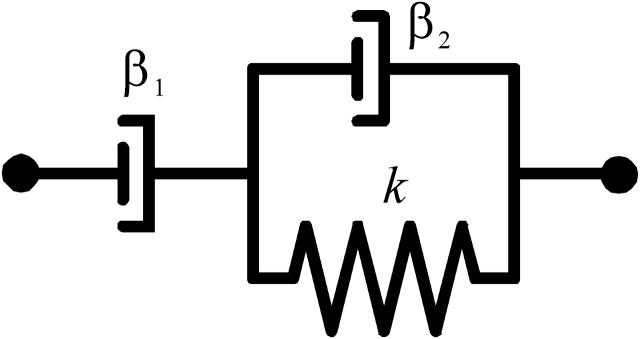
From previous work (Bausch et al., 1998), it is well known that the behavior of the cytoplasm upon the action of a mechanical force can be well described by a viscoelastic model. The viscoelastic model (Feneberg et al., 2001) that was used is shown in Fig. 5. It consists of a spring, characterized by spring constant k, and two dashpots, characterized by viscous drag β1 and β2. In this model, the response of a bead to a force step shows two regimes: a fast initial elastic response of the bead followed by a slow viscous (or creep) response. This model can be used to model one-dimensional motions of a bead but can also be adapted to model 2D bead displacements as required in this work. The 2D trajectory of a bead due to a time-varying force is given by Eq. 4 (assuming homogeneous viscoelastic properties):
 |
(4) |
where the origin (x,y) = (0,0) is defined as the initial position of the bead (for t = 0 s). This model appeared to be very well suited to describe the experimental data. From a fit of the model to the experimental data, quantitative information about the viscoelastic properties k, β1, and β2 are obtained. These parameters are usually converted into the bead diameter dbead independent elasticity μ = k/g and viscosity η = β/g, with g a geometrical factor given by g = 3πdbead, where dbead denotes the bead diameter.
FIGURE 5.
Mechanical equivalent circuitry that is used to model the viscoelastic behavior of the bead movements consisting of a dashpot (β1) to model the viscous behavior in series with a Kelvin body (spring (k) in parallel with a dashpot (β2)).
RESULTS
Magnetic tweezers design
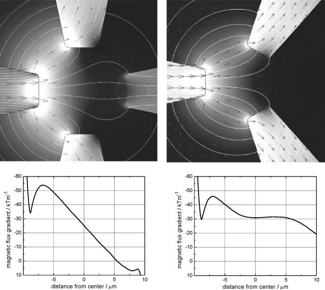
To fit a single cell, the extremities of the pole tips were positioned on a circle with a 20-micron radius, leaving a working area of ∼20 × 20 μm2. The number of poles should be at least three to allow full 2D manipulation. Both three- and four-pole magnetic tweezers were evaluated. A higher number of poles (≥5) did not give better results. Fig. 6 shows both the geometries that were evaluated. The simulations performed here were limited to 2D geometrical models and thus assume infinitely thick poles. Flux generated in the left pole is carried away by the other poles, thus creating a gradient in the magnetic flux directed toward the left pole. Fig. 6 also gives the gradient in the flux density measured along the line defined by the extremity of the left pole and the center of the magnetic tweezers. The input flux density was chosen such that the pole tips had a magnetization of 1.8 T (the saturation magnetization). As such, the presented gradients in the flux density can be considered as an upper limit. Clearly, both pole geometries result in similar gradients of 3 × 10⁴ T m−1 at the center of the tweezers. However, the three-pole geometry shows a much more homogenous gradient at the different distances. Especially in the central 10 μm, the gradient is homogenous within 10%. To further optimize the geometry, pole tip sizes were varied from 4 to 12 μm in diameter. Results (not shown) indicate that gradients in the flux density do not vary significantly with pole tip diameter.
FIGURE 6.
Spatial distribution of the magnetic flux density obtained by numerical simulations for (upper left) a four-pole geometry and (upper right) a three-pole geometry. In both cases, the incoming flux is from the left pole. (Lower left) Magnetic flux density gradients along a horizontal line through the center of the tweezers in case of the four-pole structure and (lower right) as (lower left) but for the three-pole structure.
Based on the results above, a three-pole geometry with tip diameters of 5 μm was fabricated and characterized. The method of fabrication of the poles was described previously (deVries et al., 2004).
Characterization
The fabricated three-pole magnetic structures used in these experiments have a measured thickness of 5 μm. The magnetic properties of the poles were measured with a VSM (vibrating sample magnetometer). From these measurements, the following parameters could be obtained: saturation magnetization Msat = 1.1 × 10³ kA m−1; coercive force Hc = 9 kA m−1, and the remanesence Br = 5 × 10² kA m−1.
Force calibration
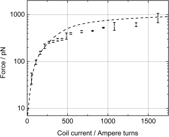
In Fig. 7, the force on a 2.8-μm M280 Dynal bead is plotted against the coil current. Forces that were achieved show a saturation of ∼1 nN for high coil currents. Fig. 7 also gives the theoretical saturation curve. In calculating the theoretical curve, the saturation properties of the cobalt layer were included by using a flux-dependent magnetic permeability as defined in Eq. 5:
 |
(5) |
where M(B), the flux-dependent magnetization was derived from measured M versus H data of the electroplated cobalt layers that were used for the magnetic poles. Furthermore, to include the effect of a limited thickness of the magnetic poles, a 3D simulation has been performed for estimating the field gradient in the center of the trap. Due to the complexity of the model, solutions could only be obtained with a relatively coarse mesh. The 2D model overestimates the gradient in the flux density by a factor of 3.0 ± 0.3 for the 5-μm thick magnetic poles.
FIGURE 7.
Measured (circles) and calculated (dashed line) forces exerted on a magnetic bead (M280 from Dynal) positioned at the center of a three-pole magnetic tweezers plotted for different coil currents.
Using the measured force on the magnetic bead (with a magnetization m = 1.3 × 10⁻¹³ A m2), the maximum achievable gradient in the magnetic flux density was calculated to be ∇B = 8 × 10³ T m−1. It is noted that this value is four times smaller than that calculated earlier (∇B = 3 × 10⁴ T m−1, see above). This reduction is partly explained by the 2D versus 3D calculation which accounts for a factor of 3. Furthermore, there is a difference in the maximum saturation for cobalt (1.85 T) which is used in the 2D calculations and the saturation of the realized cobalt poles (1.38 T), which accounts for another reduction in the gradient of a factor of 1.3, which sums up to a total reduction of 1.3 × 3 = 4.
From the 3D model, it was also possible to obtain the gradient in the magnetic flux density in the direction perpendicular to the surface as defined by the magnetic poles. This gradient will result in a “perpendicular” force in the corresponding direction. The calculations show that the amplitude of this force at a position in the center of the tweezers and within the thickness of the poles is two orders of magnitude lower than the force toward the poles. During experiments with beads inside living cells (see Manipulation of small beads inside live cells), no noticeable effect of this small force was observed during the course of the experiment, although small displacements of the bead out of the focal plane of the microscope would have been clearly visible.
Manipulation of small beads inside live cells
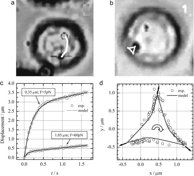
A granulocyte that contained a single magnetic bead was maneuvered in between the poles of the magnetic tweezers. Once the cell with bead was in place, the manipulation of the magnetic beads was started. Fig. 8 shows the response of a magnetic bead to various ways of one-dimensional and 2D manipulation. In most cases, the magnetic beads could be easily maneuvered through the cell even at low forces of 5 pN. The bead response was modeled using Eq. 4. Both one-dimensional and 2D manipulation results could be well described by the viscoelastic model as illustrated in Fig. 8. Curve fitting of the linear movement (Fig. 8 c) resulted in the following parameters for the 1.05-μm bead: η1 = 2.9 × 101 Pa·s, η2 = 2.0 Pa·s, and μ = 2.1 × 101 Pa and for the 0.35 μm bead: η1 = 3.0 Pa·s, η2 = 0.1 Pa·s, and μ = 0.5 Pa. Fig. 8 d shows the behavior of the 1.05 μm bead if the direction of the force is cycled between the three different poles in a clockwise fashion. The experiment shows that the bead experiences an additional force to the center when the force is changed in direction as is evident from the bend in the arms of the triangle toward the center. This phenomenon nicely matches the viscoelastic model as shown and is explained by the relaxation of the strain build up in the direction of the force during the previous period in the force cycle. The continuous cycling of the force had no visible effect on the observed path of the bead during the course of the experiment. Only after several minutes was it sometimes observed that the bead got either stuck or the bead showed increased movement in one or more directions. Only data obtained in the first few minutes of an experiment were taken into account for analysis. Repeated experiments showed that the values that were obtained for the viscoelastic properties for a single cell, at a specific position within the cell, varied only 5%. Comparing obtained values at different positions within the cell, or sometimes even at different directions within a cell, or between different cells, a much larger variation was observed. For both bead sizes, five different cells were analyzed, and the corresponding spread in the values results in a geometrical standard deviation of the mean of 0.75 (i.e., 68% of the measurements are within a factor of ±0.75 of the mean). The curves shown in Fig. 8 c are typical curves that yield viscoelastic parameters close to the average values.
FIGURE 8.
Typical movements of beads inside a cell that can be induced with the current magnetic tweezers. (a) Response of a bead that experiences a constant force of 60 pN. The bead trajectory is indicated by the white curve. (b) More complex movements are possible by changing the direction of the force. In this case, a triangular movement is induced. The shown trajectories in a and b are both to scale. (c) Measurements (circles) of the displacement of a 1.05-μm and a 0.35-μm bead versus time due to a force step from 0 pN to 60 pN for the larger bead and from 0 pN to 5 pN for the smaller bead. The response clearly indicates the viscoelastic behavior and is well described by the model (solid line). (d) Bead positions when the force is alternating between the three different poles in a clockwise fashion. Clearly a triangular movement is observed as expected. The viscoelastic model describes the observed movements very well (solid line).
DISCUSSION
The main purpose of this work is to present a new type of magnetic tweezers that combines both high forces (in other words, high gradients in the magnetic flux density) with 2D manipulation. The obtained high gradient ∇B is comparable to reported single pole magnetic tweezers (Hosu et al., 2003) but almost two orders of magnitude higher than those reported for multi-pole (>2 poles) tweezers (Amblard et al., 1996; Huang et al., 2002). Further improvements can be obtained by increasing the pole thickness (currently 5 μm). Numerical calculations show that with a pole thickness larger than 20 μm, the maximum achievable gradient is approached, which is ∼3 times larger than that achieved in this work in which poles are used that have a maximum thickness of 8 μm limited by the currently used photoresist. Increasing the saturation magnetization of the pole material (in this case cobalt) by either optimization of the cobalt poles (e.g., by annealing) or by choosing other pole materials (cobalt-iron alloys are good candidates) could result in a further improvement of the gradient ∇B.
The high gradients are required to enable the use of much smaller beads than used thus far. The manipulation of 350-nm beads as demonstrated in this work is already considerably smaller than the 1.28 μm reported by others (Hosu et al., 2003), but estimations (Table 1) predict that the use of much smaller beads is feasible. The use of iron particles that show a much higher volume magnetization than the beads used so far, consisting of Fe3O4 particles embedded in a polymer matrix, allows reducing the size of the particle down to 100 nm while still enabling a force in the pN range. It is shown that such forces are adequate to manipulate small beads through the interior of a live cell. Experiments (results not shown) with 1-μm MyOne beads and with reduced coil currents indicate that even relatively large beads can be manipulated through the cell at those low pN forces.
TABLE 1.
Overview of different magnetic beads and the corresponding maximum force that can be exerted using the current magnetic tweezers
| Bead type | Diameter μm | Volume magnetization kAm−1 | Force* pN |
|---|---|---|---|
| DynaBeads-M280 (Dynal) | 2.80 | 11.5 | 1000 |
| MyOne (Dynal) | 1.05 | 28.4 | 150 |
| 47% γ-Fe3O4 (Bangs Labs) | 0.35 | 65.0 | 12 |
| 100% Iron | 0.10 | 1.7 × 10³ | 7 |
Forces for current tweezers. Maximum forces for optimized tweezers are expected to be three times higher.
Comparison of the viscoelastic properties that were determined in this study with those reported in the literature shows that for the 1.05-μm bead, both the viscosity and the elasticity are in reasonable agreement with previous results (Feneberg et al., 2001) obtained for similar bead size (1.3 μm) and comparable forces. Interestingly, this study shows that for much smaller bead sizes, the viscosities as well as the elasticity are strongly reduced even though the bead size is still larger than the expected mesh size of the cytoskeleton, which is estimated to be ∼0.1 μm (Feneberg et al., 2001; Karcher et al., 2003). The fact that the bead is still embedded in the cytoskeletal network is also apparent from the fact that the observed viscosity of 3.0 Pa·s is still more than three orders of magnitude larger that the viscosity of water. The 10-fold reduction in viscosity for the 0.35-μm bead compared to the 1.05-μm bead can be explained by realizing that the origin of the observed viscosity is the breaking of local cross-links within the cytoplasmic network. For a smaller diameter bead, much fewer bonds have to be broken; to a first approximation, the number of bonds to be broken scales with  Obviously, more experimental data are required to confirm this hypothesis. Nevertheless, it implies that the force that is required to manipulate a small bead through the cytoplasm is lower than that required for the larger beads, which is promising for future application of the current magnetic tweezers for intracellular manipulation experiments.
CONCLUSIONS
This study describes the development of a new type of magnetic tweezers that enables the exertion of high forces on magnetic beads and simultaneous control of the direction of this force. Experimental results show that field gradients of ∇B = 8 × 10³ T m−1 can be achieved with the fabricated three-pole magnetic tweezers. These results are in agreement with theoretical calculations. Based on these calculations, it is predicted that further optimization of the magnetic tweezers can yield a further three-fold improvement. Live cell experiments show that beads with diameters of 1 μm and 0.35 μm, even though they show low magnetization, are easily manipulated through the interior of a cell. These promising results lend credence to the application of magnetic tweezers for intracellular manipulation. Further research will be directed to functionalizing magnetic beads for specific applications (e.g., with fluorescent calcium indicators to locally probe calcium concentrations) and to further improvement of the magnetic tweezers with respect to force and control of bead position.
Acknowledgments
This research was supported by the Life Sciences Foundation (SLW), which is subsidized by the Netherlands Organization for Scientific Research (NWO).
We greatly acknowledge many helpful discussions with Prof. Dr. J. Greve.
APPENDIX A
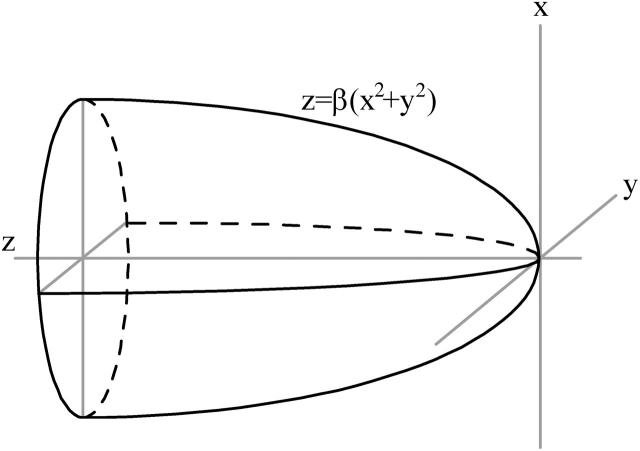
Here the gradient in the magnetic flux density ∇B that can be achieved with a single uniformly magnetized parabolic shaped pole tip is evaluated. For such a system, Fig. 9, the resulting field can be calculated analytically. The scalar magnetic potential Φ can be defined as in Eq. A1 (Nayfeh and Brussel, 1985)
 |
(A1) |
as a function of the distance z to the pole extremity. Here σ is the surface charge, and ξ the distance to the surface element dA of the pole. The integration extends over the whole pole surface, described by the quadratic equation z = βR2 with R2 = x2 + y2. For uniform magnetization Mm of the pole material, the surface charge is equal to σ = Mmcosα, with tanα = −2βR the tangent to the paraboloid. Evaluation of the integral and subsequent differentiation to z yields the following expression (Eq. A2) for the magnetic field outside the magnetic material and along the paraboloid axis (R = 0):
 |
(A2) |
The expression for the gradient in the magnetic flux density then follows from Eq. A3:
 |
(A3) |
with μ0 = 4π 10−7 Tm/A the vacuum permeability. Eq. A3 has been used to evaluate ∇B for different poles sizes as shown in Fig. 1. The optimum curvature for a given distance follows from the condition ∂F/∂β = 0 which yields β = 1/4z. Inserting this into Eq. A3 gives an expression of the maximum attainable gradient for an optimal diameter relative to the distance from the tip (Eq. A4):
 |
(A4) |
FIGURE 9.
Definition of the evaluated single parabolic shaped magnetic pole. The parameter β defines the pole tip radius.
References
- Amblard, F., B. Yuke, A. Pargellis, and S. Leibler. 1996. A magnetic manipulator for studying local rheology and micromechanical properties of biological systems. Rev. Sci. Instrum. 67:818–827. [Google Scholar]
- Bausch, A. R., W. Moller, and E. Sackmann. 1999. Measurement of local viscoelasticity and forces in living cells by magnetic tweezers. Biophys. J. 76:573–579 (and references therein). [DOI] [PMC free article] [PubMed] [Google Scholar]
- Bausch, A. R., F. Ziemann, A. A. Boulbitch, and K. Jacobson. 1998. Local measurements of viscoelastic parameters of adherent cell surfaces by magnetic bead microrheometry. Biophys. J. 75:2038–2049. [DOI] [PMC free article] [PubMed] [Google Scholar]
- Caspi, A., R. Granek, and M. Elbaum. 2002. Diffusion and directed motion in cellular transport. Phys. Rev. E66:11916–1 – 11916–12. [DOI] [PubMed] [Google Scholar]
- Davenport, R. J., G. J. L. Wuite, R. Landick, and C. Bustamante. 2000. Single-molecule study of transcriptional pausing and arrest by E-coli RNA polymerase. Science. 287:2497–2500. [DOI] [PubMed] [Google Scholar]
- deVries, A. H. B., J. S. Kanger, B. E. Krenn, and R. van Driel. 2004. Patterned electroplating of micrometer scale magnetic structures on glass substrates. J. Microelectromech. S. 13:391–395. [Google Scholar]
- Feneberg, W., M. Westphal, and E. Sackman. 2001. Dictyostelium cells' cytoplasm as an active viscoplastic body. Eur. Biophys. J. 30:284–294. [DOI] [PubMed] [Google Scholar]
- Gosse, C., and V. Croquette. 2002. Magnetic tweezers: micromanipulation and force measurement at the molecular level. Biophys. J. 82:3314–3329. [DOI] [PMC free article] [PubMed] [Google Scholar]
- Hosu, B. G., K. Jakab, P. Bánki, F. I. Tóth, and G. Forgacs. 2003. Magnetic tweezers for intracellular applications. Rev. Sci. Instrum. 74:4158–4163. [Google Scholar]
- Howard, J., A. J. Hudspeth, and R. D. Vale. 1989. Movement of microtubules by single kinesin molecules. Nature. 342:154–158. [DOI] [PubMed] [Google Scholar]
- Huang, H., C. Y. Dong, H.-S. Kwon, J. D. Sutin, R. D. Kamm, and P. T. C. So. 2002. Three-dimensional cellular deformation analysis with a two-photon magnetic manipulator workstation. Biophys. J. 82:2211–2223. [DOI] [PMC free article] [PubMed] [Google Scholar]
- Karcher, H., J. Lammerding, H. Huang, R. T. Lee, R. D. Kamm, and M. R. Kaazempur-Mofrad. 2003. A three-dimensional viscoelastic model for cell deformation with experimental verification. Biophys. J. 85:3336–3349. [DOI] [PMC free article] [PubMed] [Google Scholar]
- Laurent, V. M., S. Henon, E. Planus, R. Fodil, M. Balland, D. Isabey, and F. Gallet. 2002. Assessment of mechanical properties of adherent living cells by bead micromanipulation: comparison of magnetic twisting cytometry vs optical tweezers. J. Biomech. Eng. 124:408–421. [DOI] [PubMed] [Google Scholar]
- Nayfeh, M. H., and M. K. Brussel. 1985. Electricity and Magnetism. J. Wiley, New York.
- Neumann, K. C., E. H. Chadd, G. F. Liou, K. Bergman, and S. M. Block. 1999. Characterization of photodamage to Escherichia coli in optical traps. Biophys. J. 77:2856–2863. [DOI] [PMC free article] [PubMed] [Google Scholar]
- Peters, I. M., Y. van Kooyk, S. J. van Vliet, B. G. de Grooth, C. G. Figdor, and J. Greve. 1999. 3D single-particle tracking and optical trap measurements on adhesion proteins. Cytometry. 36:189–194. [DOI] [PubMed] [Google Scholar]
- Pope, L. H., M. L. Bennink, and J. Greve. 2002. Optical tweezers stretching of chromatin. J. Muscle Res. Cell Motil. 23:397–407. [DOI] [PubMed] [Google Scholar]
- Sacconi, L., G. Romano, R. Ballerini, M. Capitanio, M. De Pas, D. Dunlap, M. Giuntini, L. Finzi, and F. S. Pavone. 2001. Three-dimensional magneto-optic trap for micro-object manipulation. Opt. Lett. 26:1359–1361. [DOI] [PubMed] [Google Scholar]
- Strick, T. R., J. F. Allemand, D. Bensimon, A. Bensimon, and V. Croquette. 1996. The elasticity of a single supercoiled DNA molecule. Science. 276:1835–1837. [DOI] [PubMed] [Google Scholar]
- Svoboda, K., C. F. Schmidt, B. J. Schnapp, and S. M. Block. 1993. Direct observation of kinesin stepping by optical trapping interferometry. Nature. 365:721–727. [DOI] [PubMed] [Google Scholar]
- Viani, M. B., T. E. Schaffer, A. Chand, M. Rief, H. E. Gaub, and P. K. Hansma. 1999. Small cantilevers for force spectroscopy of single molecules. J. Appl. Phys. 86:2258–2262. [Google Scholar]
- Watson, J. K. 1980. Applications of Magnetism. John Wiley & Sons, New York.
- Wouters, F. S., P. J. Vermeer, and P. I. H. Bastiaens. 2001. Imaging biochemistry inside cells. Tr. Cell Biol. 11:203–211. [DOI] [PubMed] [Google Scholar]


