

Abstract
The tetraheme protein cytochrome c3 (Cyt-c3) from Desulfovibrio gigas, immobilized on a self-assembled monolayer (SAM) of 11-mercaptoundecanoic acid, is studied by theoretical and spectroscopic methods. Molecular dynamics simulations indicate that the protein docks to the negatively charged SAM via its lysine-rich domain around the exposed heme IV. Complex formation is associated with only little protein structural perturbations. This finding is in line with the resonance Raman and surface-enhanced resonance Raman (SERR) spectroscopic results that indicate essentially the same heme pocket structures for the protein in solution and adsorbed on SAM-coated Ag electrodes. Electron- and proton-binding equilibrium calculations reveal substantial negative shifts of the redox potentials compared to the protein in solution. The magnitude of these shifts decreases in the order heme IV (−161 mV) > heme III (−73 mV) > heme II (−57 mV) > heme I (−26 mV), resulting in a change of the order of reduction. These shifts originate from the distance-dependent electrostatic interactions between the SAM headgroups and the individual hemes, leading to a stabilization of the oxidized forms. The results of the potential-dependent SERR spectroscopic analyses are consistent with the theoretical predictions and afford redox potential shifts of −160 mV (heme IV), −90 mV (heme III), −70 mV (heme II), and +20 mV (heme I) relative to the experimental redox potentials for Cyt-c3 in solution. SERR spectroscopic experiments reveal electric-field-induced changes of the redox potentials also for the structurally very similar Cyt-c3 from Desulfovibrio vulgaris, although the shifts are somewhat smaller compared to Cyt-c3 from D. gigas. This study suggests that electric-field-induced redox potential shifts may also occur upon binding to biomembranes or partner proteins and thus may affect biological electron transfer processes.
INTRODUCTION
Electron transferring heme proteins are constituents of a large variety of redox chains. The proteins exert their functions at quite different positions on the electron energy scale because redox potentials can vary over a range of >700 mV (Bertrand et al., 1995). Factors that have been found to determine the intrinsic redox potential of heme proteins include the axial ligation pattern, the orientation of the ligands, the porphyrin conformation, the solvent exposure of the heme and thus the polarity and hydrophobicity of the heme pocket, and the interactions of the heme and its ligands with the protein environment (Kassner, 1972; Moore and Williams, 1977; Stellwagen, 1978; Valentine et al., 1979; Fisher and Sligar, 1985; Moore, 1983; Dolla et al., 1994; Bertrand et al., 1995; Springs et al., 2002). These interactions frequently involve protonable groups in the protein and thus account for a pronounced pH dependence of the redox potential that is known as the redox-Bohr effect (Papa et al., 1979; Xavier, 1985, 2004; Turner et al., 1996; Louro et al., 1998, 2001; Capitanio et al., 2000; Bento et al., 2003, 2004).
Other external factors are less well understood. This is particularly true for electric fields that are generated by potential gradients across membranes and by the local charge distribution on membrane surfaces or binding domains of partner proteins. Because biological redox reactions of heme proteins take place at or in membranes or in protein-protein complexes, deeper knowledge is desirable on how electric fields may affect redox potentials and the electron-transferring properties of heme proteins.
An attractive approach for studying such effects is based on self-assembled monolayers (SAM) of alkyl thiol derivatives carrying charged headgroups such as carboxylates to which proteins can be bound. These monolayers mimic some important features of biological interfaces and offer various possibilities for examining electric field effects on the immobilized proteins by experimental and theoretical methods. SAM-coated Ag or Au electrodes allow employing surface-enhanced resonance Raman (SERR) spectroscopy to probe the heme structure of the adsorbed proteins as a function of the electric-field strength that can be controlled by the thickness of the SAM, the kind of headgroups, and the electrode potential (Murgida and Hildebrandt, 2004). This approach has been used to elucidate the electric-field dependence of the thermodynamics and kinetics of the interfacial (redox) reactions specifically of the soluble heme protein cytochrome c (Murgida and Hildebrandt, 2001a,b, 2004) and has been extended, more recently, also to the membrane-bound heme enzyme cytochrome c oxidase (Friedrich et al., 2004). In this respect, SERR spectroscopy is a particularly powerful technique because it allows correlating redox potential changes with alterations of the molecular structure of the heme site, thereby contributing to a description of the electric field effects on a molecular level.
Due to its regular structural organization, SAMs are also suitable for applying theoretical methods. Molecular dynamics (MD) simulation studies of redox proteins on SAMs of different types have been reported (Tobias et al., 1996; Nordgren et al., 2002; Zhou et al., 2004). These studies aimed to understand the conformational behavior of cytochrome c on these interfaces. To our knowledge, an integrated study of redox proteins on SAMs with redox potential estimation has not yet been reported.
In this work, we present a combined theoretical and experimental study on the soluble tetraheme protein cytochrome c3 (Cyt-c3) using MD simulations and thermodynamic calculations as well as SERR spectroscopy. Type I Cyt-c3 (Valente et al., 2001) is an attractive model protein because due to its relatively small size it is still treatable by time-consuming theoretical methods. Detailed theoretical investigations have been carried out to predict redox potentials and their coupling with internal acid-base equilibria for the protein in solution as well as bound to its partner protein (Baptista et al., 1999; Martel et al., 1999; Teixeira et al., 2002, 2004; Bento et al., 2004). The docking site of Cyt-c3 for binding to its natural reaction partners is constituted by a well-defined cationic domain (Florens et al., 1995; Matias et al., 1999; Teixeira et al., 2004) that ensures also an efficient binding to anionic SAMs in a largely uniform orientation as a prerequisite for SERR spectroscopic studies (Simaan et al., 2002).
The objective of this work is to determine how the individual redox potentials of the four hemes of Cyt-c3 are affected upon binding to the SAM, and to assess the relevance of these effects for the natural redox processes.
MATERIALS AND METHODS
Materials
11-Mercaptoundecanoic acid (C11) was purchased from Sigma (St. Louis, MO) and used without further purification. Cyt-c3 from Desulfovibrio gigas and Desulfovibrio vulgaris was purified as described previously (Louro et al., 1998; Turner et al., 1992).
RR and SERR spectroscopy
RR and SERR spectra were measured with 413-nm continuous-wave excitation using a Kr-ion laser (Coherent 302) with a power of ∼60 mW at the sample. The scattered light (90°) was focused onto the entrance slit of a double monochromator (ISA, U1000) working as a spectrograph and equipped with a liquid-nitrogen cooled CCD camera. The spectral bandwidth was 4 cm−1 and the increment per data point 0.53 cm−1. The total accumulation time of the spectra was between 5 and 30 s. After background subtraction the spectra were subjected to a component analysis in which complete spectra of the individual species are fitted to the measured spectra (Murgida and Hildebrandt, 2001a). For SERR spectroscopic experiments a homebuilt rotating electrode was used. Before and during the SERR experiments, the electrochemical cell was purged by a continuous stream of catalytically purified oxygen-free Ar to remove oxygen from the solution. A detailed description of the electrochemical setup as well as of the protocol for preparing SER-active SAM-coated Ag electrodes is given elsewhere (Murgida and Hildebrandt, 2001a,b). Cyt-c3 was immobilized on the SAM-coated electrode from a diluted solution (10−7 M) at pH 7.0 in analogy to previous experiments with Cyt-c (Murgida and Hildebrandt, 2001a,b). All potentials cited in this work refer to normal hydrogen electrode. For RR experiments, the sample (10−5 M Cyt-c3) was deposited into a rotating cell to avoid laser-induced degradation of the protein. Solutions of the reduced protein were obtained by addition of dithionite to the deaerated sample.
Calculations of a self-assembled monolayer of 11-mercaptoundecanoic acid
A C11 SAM, composed of 512 molecules was generated using a geometric algorithm that distributes the molecules in vertices and centers in a squared grid. This algorithm allows implementation of periodic boundary conditions when required for the MD simulations. The maximum charge density on the SAM headgroups as estimated for C11 SAMs (Murgida and Hildebrandt, 2001a) was used to calculate the size of the grid that corresponds to this charge density. The resulting square grid has sides with ∼100.3 Å in the x- and y-directions. The geometric algorithm places the position of the sulfur atom, whereas the aliphatic chain with its terminal carboxylate function is built up in z-direction. The metal surface is not modeled in the studies described in this work. Molecular topologies for protonated and deprotonated versions of C11 were constructed using standard GROMOS96 parameters (43A1 force field) (Scott et al., 1999; Van Gunsteren et al., 1996). To set up the SAM for the proton equilibrium calculations, only deprotonated C11 was considered and the energy of the system was minimized with GROMOS96 (Van Gunsteren et al., 1996), using 2000 steps of the steepest descents method. In this calculation, electrostatic interactions were calculated using a modified version of the simulator implementing distance-dependent electrostatics (Solmajer and Mehler, 1991). Continuum electrostatic and Monte Carlo (MC) simulations, as described below, were used to calculate the average proton population in each acidic group.
The proton population in the circular region of the grid is quite stable up to the edge zone of the grid (Fig. 1). Up to 30 Å it is almost constant and we considered this region for the estimation of the theoretical limit of an infinite grid. The pKa at pH 7 for this zone is 7.9, which compares reasonably with the pKa of 8.2 determined in previous experiments (Murgida and Hildebrandt, 2001b). Therefore, the methodology is considered to simulate the titration process at the SAM well, and the results of these simulations were used for setting up a 512 C11 SAM with the correct proportion (453) of protonated groups. An exchange MC in the protonation/deprotonation space, considering periodic boundary conditions, was used to model the distribution of protonated/deprotonated groups. This MC method used an unshielded electrostatic potential and 0/−1 charges placed in the position of the carboxylate carbon. For setting up the 512 SAM, the final configuration was taken after 40,000 MC steps.
FIGURE 1.

Simulated pKa at pH 7 of the acidic groups of the SAM-containing 512 C11 carboxyl-terminated alkyl thiols. Each point corresponds to acidic groups contained in a circular region that spans from the previous circular region (or zero for the first point) up to the distance stated in the x axis.
The SAM generated in this way was solvated with simple-point-charge water (Hermans et al., 1984) and equilibrated at the experimental density. Besides the x- and y-dimensions, a space of ∼60 Å above the monolayer was considered to allow for the subsequent placement of the protein (see below). The final box dimensions were 100.3 × 100.3 × 75 Å. Fifty-nine sodium ions were added to balance the charge on the SAM, resulting in a system with 66,594 atoms. This system was simulated for 4 ns considering the C11 sulfur atom restrained using harmonic restrains of 105 kJ mol−1 nm−2, and the final configuration was used for docking Cyt-c3.
Simulation of cytochrome c3 in solution
The x-ray structure of Cyt-c3 from D. gigas (Matias et al., 1996) was the starting point of this study. The bound calcium ion and internal water molecules were included, and the whole system was solvated in water in a rectangular box with 52.3 × 59.6 × 66.1 Å size. The topology of the hemes was made with GROMOS96 parameters (Scott et al., 1999; Van Gunsteren et al., 1996) and charges as specified before (Martel et al., 1999). One sodium ion was added to balance the charge of the protein, resulting in a system with 20,144 atoms, which was simulated for 4 ns. The evolution of the root-mean-square (rms) deviation from the x-ray structure is shown in Fig. 2. The simulation of Cyt-c3 in solution is rapidly stabilized after ∼1 ns, such that we used the 2-ns structure to start the simulations on the C11 SAM.
FIGURE 2.

Time evolution of the rms deviation of Cα atoms from the x-ray structure. The thin line corresponds to the simulation of the free Cyt-c3 in solution, and spans from 0 to 4000 ps. The thick line corresponds to the simulation of Cyt-c3 on the C11 monolayer. It spans from 2000 to 6500 ps, with the starting conformation taken from the 2000-ps simulation of the free Cyt-c3 solution, corresponding to a simulation period of 4500 ps.
Simulation of cytochrome c3 on the C11 SAM monolayer
The Cyt-c3 conformation including 11 internal water molecules that was obtained after 2 ns, was used for docking the protein on the C11 SAM conformation obtained after 4 ns. Only the C11 groups were considered in the docking studies, whereas water molecules and counterions were excluded. Docking studies were performed similarly to previous works (Cunha et al., 1999), using Autodock 2.4 (Goodsell et al., 1993; Goodsell and Olson, 1990), and a 70 × 70 × 70 Å grid in the center of the C11 SAM. All lowest-energy configurations revealed very similar interactions of the heme IV zone (lysine patch) of Cyt-c3 with the surface of the C11 SAM, which is a typical behavior for the interactions of this protein with redox partners (Matias et al., 1999, 2001; Teixeira et al., 2004). A configuration almost at the center of the grid was chosen for starting new molecular dynamics simulations. The docked Cyt-c3 structure was merged with the original C11 SAM 4-ns conformation containing water molecules and counterions. Water molecules colliding with the protein at a distance lower than 2.3 Å from any protein atom were eliminated, and the sodium ions under the same circumstances, were moved away but not eliminated. To account for the extra negative charge brought about by the protein, an additional sodium ion was added. The energy of the entire system was minimized, and slowly released using restrained MD for 50 ps with the protein and C11 restrained, and for 50 ps with the protein Cα atoms and C11 sulfur atoms restrained. Subsequently, a production run of 4.5 ns was calculated, considering the C11 sulfur atom restrained using harmonic restrains of 105 kJ mol−1 nm−2.
Redox equilibrium calculations
Using a combination of continuum electrostatics and MC methods (vide infra), redox affinities of the different hemes of Cyt-c3 were estimated under the different simulation conditions. Our objective was to compare the redox potential that Cyt-c3 displays in solution with that of Cyt-c3 immobilized on the monolayer. We therefore selected conformations from the two MD simulations and applied the thermodynamic calculations, setting the pH to 7.0, and scanning the redox potential between −600 and 100 mV. From simulations of Cyt-c3 in solution we selected nine conformations from 2000 to 4000 ps at 250-ps intervals. For the Cyt-c3 on the C11 SAM, we selected nine conformations from 4500 to 6500 ps considering the timescale displayed in Fig. 2, using as well 250-ps intervals.
Molecular dynamics simulations
Although molecular topologies and several initialization procedures were carried out with the GROMOS96 package using the 43A1 force field (Scott et al., 1999; Van Gunsteren et al., 1996), MD simulations were run using the GROMACS 3.1.4 package (Lindahl et al., 2001) after proper conversion. Simulations were run at constant volume and the temperature was maintained around 300 K by coupling the system to a heat bath (Berendsen et al., 1984), with separate coupling of solutes and solvent and temperature coupling constants of 0.1 ps. The time step for the integration of equations of motion was 0.002 ps. A cutoff of 14 Å was used for van der Waals interactions and a smooth particle mesh Ewald method (Essmann et al., 1995) was used for long-range electrostatic interactions from a 9-Å cutoff. Neighbor lists were updated every 10 steps. The LINCS algorithm (Hess et al., 1997) was employed to keep all bonds at their equilibrium values and the SETTLE algorithm (Miyamoto and Kollman, 1992) was used for keeping water molecules rigid.
Thermodynamic modeling of electron and proton titration
The study of the joint equilibrium thermodynamics of electron and proton binding at different pH values and redox potentials was performed following procedures described before (Baptista et al., 1999; Baptista and Soares, 2001; Teixeira et al., 2002), using continuum electrostatics and MC methodologies. The continuum electrostatics methods were used to compute the individual and interaction terms of the binding free energy of electrons and protons (Baptista et al., 1999; Teixeira et al., 2002). These free-energy terms were then used in a MC method (Baptista et al., 1999; Baptista and Soares, 2001; Teixeira et al., 2002) that samples the binding states. Binding free energies are calculated with the MEAD (version 2.2.0) package (Bashford, 1997; Bashford and Gerwert, 1992). The temperature and the ionic strength were 300 K and 6.25 mM, respectively, and the ion exclusion layer was set to 2.0 Å. The solvent probe radius was 1.4 Å. For the dielectric constant a value of 20 was used for the protein and the SAM and a value of 80 was taken for the solvent. These values were found to reproduce the pKa values of proteins more accurately (Baptista and Soares, 2001). A three-step focusing procedure (Gilson et al., 1987) was employed with the first step using a 100 × 100 × 100 Å point grids with 3.0-Å spacing, followed by two steps with 80 × 80 × 80 Å point grids using 1.0- and 0.25-Å spacing, respectively. The MC sampling of binding states was performed with the Proton and Electron Titration (PETIT) program (Baptista et al., 1999; Baptista and Soares, 2001). The number of MC steps was 105.
RESULTS AND DISCUSSION
Simulation of cytochrome c3 in contact with the SAM
Cyt-c3 from D. gigas displays an increased deviation from the x-ray structure after being placed on the monolayer (Fig. 2). This deviation is slightly higher than that found for the protein in solution, even though it is within the typical deviation for solvated proteins (∼2 Å rms deviation). In general, the deviations are distributed over the entire protein, however, the C-terminal helix (in the lower left part of Fig. 3), which contacts the monolayer, is significantly displaced from its crystal structure position. The final snapshot of the simulation is represented in Fig. 3.
FIGURE 3.

Structural model Cyt-c3 from D. gigas on the SAM obtained after 4500-ps MD simulation (see Fig. 2). The protein is represented using secondary structure cartoons, with the heme groups and the C11 rendered as sticks. The yellow sphere corresponds to the bound calcium ion in the Cyt-c3 structure. The carbon atoms on the heme are colored in yellow to distinguish them from the carbon atoms of the SAM, which are colored in green. The figure was produced with PyMOL (W. L. DeLano, The PyMOL Molecular Graphics System, 2002, online at http://www.pymol.org).
During the simulation the distance between Cyt-c3 and the monolayer decreases (results not shown), evidencing a close contact between these two entities. Salt bridges between the cationic side chains of the lysine patch surrounding heme IV and the deprotonated C11 carboxylate as well as hydrogen bonds with protonated carboxyl groups of the SAM are formed. Despite this tight contact between Cyt-c3 and the SAM, the interface also contains some water molecules. The accessible surface is reduced in the complex with increasing simulation time (results not shown), being almost stabilized after ∼2000–2500-ps simulation. This loss corresponds to 12% of the average total accessible surface determined in the simulation of Cyt-c3 in solution. This calculation does not consider the quite floppy interfacial water molecules, meaning that the true excluded surface is probably larger.
Electron affinity of the heme groups in cytochrome c3 in contact with the SAM
The main objective of these studies is to elucidate the consequences of Cyt-c3 immobilization on the SAM for the electron affinity of the heme groups. To compensate systematic errors associated with the theoretical methods, we focused on the binding-induced redox potential shifts obtained from the calculations for Cyt-c3 in solution and immobilized on the SAM. As shown in Fig. 4, the individual midpoint redox potentials vary considerably along the two trajectories. Association with the monolayer has dramatic consequences on the overall electron affinity of all hemes as reflected by the substantial decrease of the redox potentials. Furthermore, the differences between the redox potential of the individual hemes are also altered in the immobilized state as compared to the protein in solution. A more detailed picture is provided by averaging the titration curves (Fig. 5). The results show that heme IV experiences the largest shift (−161 mV), followed by heme III (−73 mV), heme II (−57 mV), and finally heme I that shows only a relatively small shift (−26 mV). The overall titration curve (Fig. 5) reveals a shift of −78 mV upon binding to the SAM.
FIGURE 4.

Time evolution of the midpoint redox potentials for the different hemes of Cyt-c3 in different simulation conditions. Values from 2000 to 4000 ps correspond to the simulation of the free Cyt-c3 in solution, whereas values from 4500 to 6500 ps correspond to the simulation of Cyt-c3 immobilized on the SAM. The individual hemes are represented by the following symbols: heme I, triangles; heme II, circles; heme III, diamonds; heme IV, squares.
FIGURE 5.

Comparison between the redox titration curves for the different hemes of Cyt-c3, in solution (thin lines) and immobilized on the SAM (thick lines). The curves represent averages from the nine thermodynamic calculations done for both trajectories. Labels contain the value of the midpoint potentials for each situation. (A) heme I; (B) heme II; (C) heme III; (D) heme IV; (E) total titration.
RR spectroscopic measurements
RR spectra of Cyt-c3 from D. gigas in solution were obtained in resonance with the Soret absorption band, which does not display any fine structure in both the fully oxidized and fully reduced form. The RR spectra, measured between 200 and 1700 cm−1, provide only a few indications for spectral heterogeneities that may reflect slight structural differences between the four bis-His coordinated hemes. In the frequency region above 1300 cm−1, which includes the C-C and C-N stretching modes of the heme skeleton (Hu et al., 1993), we only note unusually large bandwidths for a few modes (e.g., ν3; Fig. 6). These differences, however, are not sufficiently pronounced to disentangle the measured RR spectra in terms of individual component spectra. This conclusion also holds for the frequency region below 900 cm−1 (data not shown), which is considered to be more sensitive toward alterations of the heme-protein interactions. Thus, the RR spectra of both the fully oxidized and fully reduced form of Cyt-c3 could be perfectly simulated by a single-component spectrum of an oxidized six-coordinated low spin (6cLS) and a reduced 6cLS configuration, respectively (Table 1). Furthermore, the spectral parameters of these component spectra were very similar for Cyt-c3 from D. gigas and D. vulgaris indicating that both proteins exhibit essentially the same heme structures.
FIGURE 6.

RR spectra of Cyt-c3 from D. gigas in solution at pH 7.0, measured with 413-nm excitation, (A) in the fully oxidized and (B) fully reduced state.
TABLE 1.
Spectral parameters of heme marker bands ν4 and ν3 of oxidized and reduced Cyt-c3 from D. vulgaris in solution and immobilized on the SAM-coated electrode
| Oxidized
|
Reduced
|
||||||
|---|---|---|---|---|---|---|---|
| Mode | Solution | Adsorbed* | Solution | Adsorbed RedA | Adsorbed RedB | ||
| ν4 | Frequency/cm−1 | 1373.3 | 1374.1 | 1370.2 | 1358.5 | 1358.4 | 1365.2 |
| Half-width/cm−1 | 12.8 | 11.1 | 12.4 | 11.6 | 11.0 | 11.1 | |
| ν3 | Frequency/cm−1 | 1504.8 | 1507.4 | 1503.2 | 1492.0 | 1490.9 | 1497.2 |
| Half-width/cm−1 | 16.0 | 6.3 | 9.6 | 12.2 | 11.5 | 11.3 | |
For the quantitative analysis the component spectra of the oxidized species were combined.
SERR spectroscopic experiments
For SERR spectroscopic experiments, Cyt-c3 from D. gigas and D. vulgaris was electrostatically immobilized on electrochemically roughened Ag electrodes that were coated with C11 SAMs. Adsorption of the basic proteins to the anionic monolayer occurs spontaneously when the electrode is brought in contact with diluted solutions of Cyt-c3 at pH 7. At electrode potentials above −0.1 V, the SERR spectra exclusively display bands that are characteristic of a ferric 6cLS heme (Fig. 7). Band-fitting analyses indicate a spectral heterogeneity that is larger than in the RR spectra. In fact, a substantially better fit was achieved by using two-component spectra of 6cLS ferric hemes rather than one. At electrode potentials below −0.4 V, the adsorbed proteins are predominantly in the fully reduced state. In this case, however, the SERR spectra display additional bands that have no counterparts in the RR spectra of the fully reduced Cyt-c3 in solution. These bands (RedB) are somewhat higher in frequency as compared to the main reduced component (RedA) but still within the range characteristic of a ferrous 6cLS heme (Table 1).
FIGURE 7.

SERR spectra of Cyt-c3 from D. vulgaris immobilized on a SAM-coated Ag electrode (pH 7.0), measured with 413-nm excitation at different potentials, (A) −0.21V, (B) −0.26 V, and (C) −0.29 V. The fitted component spectra of Ox, RedA, and RedB are represented by the dashed-dotted, dashed, and dotted lines, respectively.
A satisfactory global fit to all SERR spectra measured in the potential range between 0.0 and −0.5 V is obtained on the basis of the component spectra of two reduced and two oxidized 6cLS hemes. However, the two component spectra of the ferric state cannot be related to structurally distinct species or individual heme groups. The corresponding component spectra are very similar and slight variations of the spectral parameters in either spectrum only affect their relative contributions but not the total contribution of the ferric state. Because, in addition, the quality of the global fit does not sensitively depend on such variations of the individual spectral parameters of these species, a unique determination of the component spectra for these ferric 6cLS forms was not possible. Thus, the sum of the ferric 6cLS component spectra was assigned to the total contribution of all ferric hemes (Ox) in Cyt-c3.
Quantitative analysis of the SERR spectra
The relative intensities, which are the amplitudes of the component spectra Ij, are related to the relative concentrations cj of the individual species j according to
 |
(1) |
where fj are factors that are proportional to the reciprocal SERR scattering cross sections (Murgida and Hildebrandt, 2001a). For the native reduced and oxidized Cyt-c, it has been shown that the ratio of the SERR cross sections is equal to the ratio of the RR cross sections, which in turn can readily be determined experimentally (Simaan et al., 2002).
 |
(2) |
Because redox-linked changes of the distance and orientation of the hemes with respect to the electrode can be ruled out, for each heme group the surface enhancement of the RR scattering is likely to be same in the ferric and the ferrous state. Thus, Eq. 2 holds for each of the four hemes. However, the surface enhancement is certainly different for the various hemes. According to the simulations (Fig. 3), hemes IV and I adopt an orientation perpendicular to the electrode surface such that for these groups the different surface enhancement is controlled by the distance to the metal surface, which is larger by ∼10 Å for heme I. This larger distance may account for an approximately five times weaker surface enhancement compared to heme IV as estimated from previous studies on cytochrome c (Murgida and Hildebrandt, 2001a). Hemes II and III exhibit only a slightly larger distance than heme IV but their orientations are tilted or coplanar with respect to the surface, which is less favorable for the surface enhancement of the RR scattering as compared to the perpendicular orientation of the hemes I and IV (Moskovits, 1985).
In a first approximation we therefore assume that: i), the surface enhancement for the hemes I, II, and III is the same, and ii), their spectral weight in the SERR spectra is comparable to that of heme IV. For a better comparison, one may multiply the intensities of the reduced forms RedA and RedB by R (Eq. 2) to obtain normalized spectral contributions for all spectroscopically distinguishable species according to
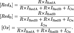 |
(3) |
Plotting these data as function of the electrode potential (Fig. 8) reveals that the spectral contribution of RedA comprises ∼60% at electrode potentials <−0.4 V. Taking into account the estimated differential surface enhancement for the individual hemes, one may therefore assign spectral species RedA to the hemes I, II, and III, which are essentially fully reduced at such negative potentials. Then RedB is attributed to heme IV. This assignment is not unambiguous a priori but it is supported by the following arguments. First, the spectral parameters of the RedB reveal small but noticeable differences compared to those of ferrous Cyt-c3 in solution. These differences may reflect slight structural distortions or alterations of the vibrational energy levels brought about by the electric field in the SAM/protein interface and by protein conformational changes due to immobilization. MD simulations in fact reveal conformational perturbations that are found for the C-terminal helix in the vicinity of heme IV, which is in close contact with the negatively charged headgroups of the SAM (Fig. 3). Thus, slight changes of the spectral parameters are indeed expected for heme IV. Conversely, such effects should be much smaller for the more remote heme groups, which hence are attributed to that spectral form (RedA) that is very similar to the ferrous Cyt-c3 in solution. Second, the assignment of RedB to heme IV implies that this heme exhibits the most negative midpoint potential as it is predicted by the thermodynamic redox potential calculations (Fig. 5). On the other hand, the alternative assignment of RedA and RedB yields midpoint potentials (cf. Simaan et al., 2002) that are in sharp contradiction with the calculations.
FIGURE 8.

Relative intensities of Ox (○), RedA (▴), and RedB (□) of Cyt-c3 from D. vulgaris (top) and D. gigas (bottom) immobilized on the coated electrode (pH 7.0). The data were obtained from the component analysis of the SERR spectra. Further details are given in the text.
SERR spectroscopic determination of the redox potentials
The midpoint potentials of heme IV, EIV were determined from the experimental data according to the Nernst equation for a one-electron redox couple
 |
(4) |
where F, R, T are the Faraday constant, the gas constant, and the temperature. Particularly, for the D. gigas protein, the error is relatively large (∼±30 mV) due to the low relative spectral contributions of this RedB component. For the same reason, the semilogarithmic Nernstian plots displays distinct deviations from the ideal slope corresponding to z = 1. On the basis of these fits, Eq. 4 is then used to calculate the contribution of the oxidized hemes I, II, and III, OxA, according to
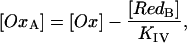 |
(5) |
with
 |
(6) |
the concentration ratio of RedA and OxA is expressed in terms of the redox equilibrium constants Kj, which in turn are defined corresponding to Eq. 4. Finally, Eq. 6 is fitted to the experimental data to yield the midpoint potentials Ej for the hemes I, II, and III (Fig. 9). The potentials that are derived from the SERR spectroscopic experiments refer to those potentials at which the respective hemes exist in 1:1 equilibria between the oxidized and the reduced form. However, due to the potential drops across the Ag/SAM/protein the values have a shift brought about by the interfacial potential drops across the electrode/SAM/protein/solution interfaces (Murgida and Hildebrandt, 2001a). As a result, the potential sensed by the protein redox site differs from that poised at the working electrode. For cytochrome c immobilized under the same conditions this potential shift has been determined to be −40 mV at pH 7.0 (Murgida and Hildebrandt, 2001a). Adapting the formalism employed in that study to Cyt-c3 and assuming the same charge density in the SAM/protein interface and the same surface coverage of the protein, the potential shifts at pH 7.0 for heme IV, hemes II/III, and heme I are estimated to be −30, −20, and −10 mV, respectively. Magnitude and sign of the shifts crucially depend on the charge density in the SAM/protein interface and thus on the protonation state of the carboxylate headgroups.
FIGURE 9.

Analysis of the midpoint potentials of immobilized Cyt-c3 from D. gigas at pH 7.0. The plot displays the potential dependence of [RedA]/[OxA] with the solid line obtained by a fit of Eq. 6 to the experimental data.
For Cyt-c3 from D. gigas at pH 7.0, the experimental data can be compared with calculated redox potential shifts “adsorbed minus solution,” revealing a very good agreement for heme IV (Table 2). The assignment of three midpoint potentials determined according to Eq. 6 to the remaining hemes is straightforward by comparison with the calculated data. For the hemes II and III the calculated redox potential shifts are very similar (−60 and −70 mV) and thus match very well the experimentally determined data. Then, the third midpoint potential at ∼−0.27 V is attributed to heme I. This potential corresponds to a slight positive potential shift but the discrepancy compared to the calculated small negative shift is within the accuracy of the experiments and the fitting analysis as well as of the calculations. On the basis of the redox potentials derived from the SERR spectroscopic data, the total (apparent) midpoint potential is calculated to be −0.34 V, which is ∼80 mV more negative than that derived from the experimental data in solution (Louro et al., 1998). Also this experimentally determined shift (“immobilized” minus “solution”) is in good agreement with the calculated shift of ∼−80 mV (Fig. 5).
TABLE 2.
Experimental and calculated midpoint potentials (in V) of Cyt-c3 from D. gigas in solution and immobilized on the SAM-coated electrode
| Heme I | Heme II | Heme III | Heme IV | |
|---|---|---|---|---|
| Solution, experimental* | −0.287 | −0.279 | −0.262 | −0.183 |
| Solution, calculated† | −0.306 | −0.327 | −0.308 | −0.296 |
| Adsorbed, calculated† | −0.332 | −0.384 | −0.381 | −0.457 |
| “Adsorbed minus solution,” calculated† | −0.026 | −0.057 | −0.073 | −0.161 |
| Adsorbed, experimental (SERR)† | −0.28 | −0.37 | −0.37 | −0.42 |
| Adsorbed, experimental, corr.†‡ | −0.27 | −0.35 | −0.35 | −0.39 |
| “Adsorbed (corr.) minus solution,” experimental† | +0.02 | −0.07 | −0.09 | −0.16 |
Data taken from Louro et al. (1998).
This work.
Corrected for the interfacial potential drop according to Murgida and Hildebrandt (2001a).
Electric-field effects on the redox potentials
The most important implications of the theoretical calculations are substantial negative shifts of the redox potentials of the adsorbed Cyt-c3 as compared to the protein in solution. These results are in line with the experimental findings that reveal a particularly large redox potential shift for heme IV. To identify the factors that are responsible for these redox potential shifts, thermodynamic calculations were repeated with selected conformations of the immobilized Cyt-c3 but after elimination of the SAM. The results, shown for heme IV in Fig. 10, indicate that upon removal of the SAM the redox potential goes back to a value that is very close to that in solution. This finding implies that the slight alterations of the conformation in the immobilized Cyt-c3 have only a very small effect on the redox potential. Furthermore, thermodynamic calculations were carried out for Cyt-c3 immobilized on the SAM but with all carboxylate groups being protonated such that the monolayer has an overall charge of zero. The results differ dramatically from the original situation when the SAM is partially charged corresponding to pH 7.0, because the midpoint potentials increase to values even higher than those for free Cyt-c3 in solution. Thus, we conclude that the presence of the low dielectric constant of the monolayer destabilizes the oxidized form as compared to the protein in solution. This finding can be rationalized by considering the actual charge of the heme core excluding the propionates. Although the reduced form is neutral, the oxidized form displays a net positive charge, which is destabilized in a low dielectric medium provided by an uncharged SAM. Conversely, these results indicate that the electrostatic interactions with the charged SAM headgroups represent the crucial factor that controls the redox potential shifts of the immobilized Cyt-c3. Because the Coulombic forces decrease with increasing distance from the SAM surface, one can readily rationalize that the largest potential shift is found for the closest heme IV whereas the redox potential of the most remote heme I remains nearly unaffected. In the SERR experiments, the surface charge can be decreased by lowering the pH, and in fact preliminary data indicate that the potential shifts are smaller than at pH 7.0.
FIGURE 10.

Comparison between the redox titration curves of heme IV for Cyt-c3 from D. gigas in solution (thin dashed line), immobilized on the (partially) charged SAM (thick solid line), in the same conformation but after neutralization of the SAM surface charge (thick dashed lines), and in the same conformation but after removal from the monolayer (thin solid line).
As a result of the distance dependence of the electric-field-induced potential shifts, the order of reduction of the individual hemes is changed. For the immobilized Cyt-c3 from D. gigas at pH 7.0 this order is predicted to follow the sequence I → III → II → IV in contrast to the sequence IV → I → III → II calculated for Cyt-c3 in solution. This latter order of reduction differs somewhat from the experimental data that has been determined to be IV → III → II → I (Louro et al., 1998). This discrepancy may be attributed to the fact that for Cyt-c3 in solution the calculated and experimentally determined redox potentials are very close and there is significant uncertainty linked with the calculated potentials. Additionally, the proton capture usually associated with calculations that are based on x-ray structures (Baptista et al., 1999; Bento et al., 2004, 2003; Louro et al., 2001; Martel et al., 1999; Teixeira et al., 2002) is not adequately considered because MD simulations are carried out within the constraints of specific fixed protonation states and make the structure to acquire strong conformational characteristics of these protonation states, which will appear in the electrostatic calculations. However, the fact that this proton capture, which may modulate redox potentials, specially that of heme I (Baptista et al., 1999; Teixeira et al., 2002), is not correctly modeled, should not obscure the clarification of our major objective, which was to analyze the redox potential shifts brought about by the immobilization of the protein on the charged surface.
Adopting the same strategy for assigning the redox potentials as in Cyt-c3 from D. gigas, also in the D. vulgaris protein the largest shift refers to heme IV. The magnitude of the shift (−80 mV at pH 7.0) is two times smaller than for D. gigas. This difference may largely be attributed to the experimental and fitting errors.
Functional implications of electric-field-induced redox potential shifts
The redox potential shifts of Cyt-c3 that are induced by immobilization to the SAM are controlled by two opposing effects. Whereas the local electrostatic field of the charged headgroups causes a downshift, an incremental upshift of the redox potential results from the lowering of the dielectric constant in the surrounding of the binding domain of the immobilized protein as compared to the protein in aqueous solution. For Cyt-c3 immobilized at pH 7.0, the magnitude of this latter effect is distinctly smaller than the electric-field-induced shift but it gains importance when the charge density in the SAM/protein interface decreases. Thus, one may conclude that the interplay of surface charges and low dielectric constant may allow a fine tuning of the redox potential of the immobilized protein.
The experimental data obtained by the SERRS experiments refer to SAMs coated on an Ag electrode such that the local electric field experienced by the immobilized protein does not only include the contribution from the charges of the SAM headgroups but also of the interfacial potential drop, which can be regarded as the analog to the potential difference across a biomembrane. This latter contribution is not considered in the calculations. It is expected to be relatively small at high surface charge densities and in fact, the good agreement between calculated and experimental redox potential shifts for Cyt-c3 from D. gigas at pH 7.0 supports this conclusion. Thus, electric-field-induced shifts of the redox potentials are not necessarily restricted to proteins bound to membranes but may also occur in electrostatic complexes with partner proteins. Natural redox partners of Cyt-c3 such as [NiFe]-hydrogenase (Matias et al., 2001), the nine heme cytochrome c 9Hcc (Matias et al., 1999), [Fe]-hydrogenase (El Antak et al., 2003), and type II Cyt-c3 (Teixeira et al., 2004) exhibit negatively charged and concavely shaped binding domains that provide charge and structure complementarity for positively charged and convex binding domains of the type I Cyt-c3. In fact, MD simulations and thermodynamic calculations of such a protein-protein complex (Teixeira et al., 2004), i.e., type I and type II Cyt-c3 from D. vulgaris, have demonstrated negative redox potential shifts specifically of the hemes of the type I Cyt-c3. The largest shift is found for heme IV (−80 mV) whereas the shifts of the redox potentials of the other hemes are much smaller. Most remarkable, these results agree also quantitatively very well with the potentials obtained for the type I Cyt-c3 from D. vulgaris immobilized on the SAM-coated electrode.
Acknowledgments
The authors thank Dr. Ricardo Louro and Prof. Antonio V. Xavier for valuable discussions and critical comments.
The work was supported by grants from the Fundação para a Ciência e Tecnologia (POCTI/2001/QUI/43323 and POCTI/BME/32789/99) and the Deutsche Forschungsgemeinschaft (Sfb498, A8). R.E.D.P. acknowledges grant BPD/14414/2003 from FCT/Portugal.
References
- Baptista, A. M., P. J. Martel, and C. M. Soares. 1999. Simulation of electron-proton coupling with a Monte Carlo method: application to cytochrome c3 using continuum electrostatics. Biophys. J. 76:2978–2998. [DOI] [PMC free article] [PubMed] [Google Scholar]
- Baptista, A. M., and C. M. Soares. 2001. Some theoretical and computational aspects of the inclusion of proton isomerism in the protonation equilibrium of proteins. J. Phys. Chem. B. 105:293–309. [Google Scholar]
- Bashford, D. 1997. In Scientific Computing in Object-Oriented Parallel Environments, Vol. 1343. Y. Ishikawa, R. R. Oldehoeft, J. V. W. Reynders, and M. Tholburn, editors. Springer, Berlin, Germany. 233–240.
- Bashford, D., and K. Gerwert. 1992. Electrostatic calculations of the pKa values of ionisable groups in bacteriorhodopsin. J. Mol. Biol. 224:473–486. [DOI] [PubMed] [Google Scholar]
- Bento, I., P. M. Matias, A. M. Baptista, P. N. da Costa, W. M. A. M. van Dongen, L. M. Saraiva, T. R. Schneider, C. M. Soares, and M. A. Carrondo. 2004. Molecular basis for redox-Bohr and cooperative effects in cytochrome c3 from Desulfovibrio desulfuricans ATCC 27774: crystallographic and modelling studies of oxidised and reduced high resolution structures at pH 7.6. Proteins. 54:135–152. [DOI] [PubMed] [Google Scholar]
- Bento, I., V. H. Teixeira, A. M. Baptista, C. M. Soares, P. M. Matias, and M. A. Carrondo. 2003. Redox-Bohr and other cooperativity effects in the nine heme cytochrome c from Desulfovibrio desulfuricans ATCC 27774: crystallographic and modeling studies. J. Biol. Chem. 278:36455–36469. [DOI] [PubMed] [Google Scholar]
- Berendsen, H. J. C., J. P. M. Postma, W. F. Van Gunsteren, A. DiNola, and J. R. Haak. 1984. Molecular dynamics with coupling to an external bath. J. Chem. Phys. 81:3684–3690. [Google Scholar]
- Bertrand, P., O. Mbarki, M. Asso, L. Blanchard, F. Guerlesquin, and M. Tegoni. 1995. Control of the redox potential in c-type cytochromes: importance of the entropic contribution. Biochemistry. 34:11071–11079. [DOI] [PubMed] [Google Scholar]
- Capitanio, N., G. Capitanio, D. Boffoli, and S. Papa. 2000. The proton/electron coupling ratio at heme a and Cu-A in bovine heart cytochrome c oxidase. Biochemistry. 39:15454–15461. [DOI] [PubMed] [Google Scholar]
- Cunha, C. A., M. J. Romão, S. J. Sadeghi, F. Valetti, G. Gilardi, and C. M. Soares. 1999. Modelling of electron transfer complexes between flavodoxin and c-type cytochromes. Bioinorg. Chem. 4:360–374. [DOI] [PubMed] [Google Scholar]
- Dolla, A., L. Blanchard, F. Guerlesquin, and M. Bruschi. 1994. The protein moiety modulates the redox potential in cytochromes c. Biochimie. 76:471–479. [DOI] [PubMed] [Google Scholar]
- El Antak, L., X. Morelli, O. Bornet, C. Hatchikian, M. Czjzek, A. Dolla, and F. Guerlesquin. 2003. The cytochrome c3-[Fe]-hydrogenase electron-transfer complex: structural model by NMR restrained docking. FEBS Lett. 548:1–4. [DOI] [PubMed] [Google Scholar]
- Essmann, U., L. Perera, and M. L. Berkowitz. 1995. A smooth particle mesh ewald method. J. Chem. Phys. 103:8577–8593. [Google Scholar]
- Fisher, M. T., and S. G. Sligar. 1985. Control of heme protein redox potential and reduction rate: linear free-energy relation between potential and ferric spin state equilibrium. J. Am. Chem. Soc. 107:5018–5019. [Google Scholar]
- Florens, L., M. Ivanova, A. Dolla, M. Czjzek, R. Haser, R. Verger, and M. Bruschi. 1995. Interfacial properties of the polyheme cytochrome c3 superfamily from Desulfovibrio. Biochemistry. 34:11327–11334. [DOI] [PubMed] [Google Scholar]
- Friedrich, M., F. Gieß, R. Naumann, W. Knoll, K. Ataka, J. Heberle, J. Hrabakova, D. H. Murgida, and P. Hildebrandt. 2004. Active site structure and redox processes of cytochrome c oxidase immobilised in a novel biomimetic lipid membrane. Chem. Commun. 2376–2377. [DOI] [PubMed]
- Gilson, M. K., K. A. Sharp, and B. H. Honig. 1987. Calculating the electrostatic potential of molecules in solution: method and error assessment. J. Comput. Chem. 9:327–335. [Google Scholar]
- Goodsell, D. S., H. Lauble, C. D. Stout, and A. J. Olson. 1993. Automated docking in crystallography: analysis of the substrates of aconitase. Proteins. 17:1–10. [DOI] [PubMed] [Google Scholar]
- Goodsell, D. S., and A. J. Olson. 1990. Automated docking of substrates to proteins by simulated annealing. Proteins. 8:195–202. [DOI] [PubMed] [Google Scholar]
- Hermans, J., H. J. C. Berendsen, W. F. Van Gunsteren, and J. P. M. Postma. 1984. A consistent empirical potential for water-protein interactions. Biopolymers. 23:1513–1518. [Google Scholar]
- Hess, B., H. Bekker, H. J. C. Berendsen, and J. G. E. M. Fraaije. 1997. LINCS: a linear constraint solver for molecular simulations. J. Comput. Chem. 18:1463–1472. [Google Scholar]
- Hu, S., J. K. Morris, J. P. Singh, K. M. Smith, and T. G. Spiro. 1993. Complete assignment of cytochrome c resonance Raman spectra via enzymatic reconstitution with isotopically labelled hemes. J. Am. Chem. Soc. 115:12446–12458. [Google Scholar]
- Kassner, R. 1972. Effects of nonpolar environments on the redox potentials of heme complexes. Proc. Natl. Acad. Sci. USA. 69:2263–2267. [DOI] [PMC free article] [PubMed] [Google Scholar]
- Lindahl, E., B. Hess, and D. van der Spoel. 2001. GROMACS 3.0: a package for molecular simulation and trajectory analysis. J. Mol. Model. [Online]. 7:306–317. [Google Scholar]
- Louro, R. O., I. Bento, P. M. Matias, T. Catarino, A. M. Baptista, C. M. Soares, M. A. Carrondo, D. L. Turner, and A. V. Xavier. 2001. Conformational component in the coupled transfer of multiple electrons and protons in a monomeric tetraheme cytochrome. J. Biol. Chem. 276:44044–44051. [DOI] [PubMed] [Google Scholar]
- Louro, R. O., T. Catarino, D. L. Turner, M. A. Picarra-Pereira, I. Pacheco, J. LeGall, and A. V. Xavier. 1998. Functional and mechanistic studies of cytochrome c3 from Desulfovibrio gigas: thermodynamics of a “proton thruster”. Biochemistry. 37:15808–15815. [DOI] [PubMed] [Google Scholar]
- Martel, P., C. M. Soares, A. M. Baptista, M. Fuxreiter, G. Náray-Szabó, R. O. Louro, and M. A. Carrondo. 1999. Comparative redox and pKa calculations on cytochromes c3 from Desulfovibrio species using continuum electrostatic methods. Bioinorg. Chem. 4:73–86. [DOI] [PubMed] [Google Scholar]
- Matias, P. M., J. Morais, R. Coelho, M. A. Carrondo, K. Wilson, Z. Dauter, and L. Sieker. 1996. Cytochrome c3 from Desulfovibrio gigas: crystal structure at 1.8 Å resolution and evidence for a specific calcium-binding site. Protein Sci. 5:1342–1354. [DOI] [PMC free article] [PubMed] [Google Scholar]
- Matias, P. M., L. M. Saraiva, C. M. Soares, A. V. Coelho, J. LeGall, and M. A. Carrondo. 1999. Nine-haem cytochrome c from Desulfovibrio desulfuricans ATCC 27774: primary sequence determination, crystallographic refinement at 1.8 Å and modelling studies of its interaction with the tetrahaem cytochrome c3. Bioinorg. Chem. 4:478–494. [DOI] [PubMed] [Google Scholar]
- Matias, P. M., C. M. Soares, L. M. Saraiva, R. Coelho, J. Morais, J. LeGall, and M. A. Carrondo. 2001. [NiFe] Hydrogenase from Desulfovibrio desulfuricans ATCC 27774: gene sequencing, three-dimensional structure determination and refinement at 1.8 Å and modelling studies of its interaction with the tetra-haem cytochrome c3. Bioinorg. Chem. 6:63–81. [DOI] [PubMed] [Google Scholar]
- Miyamoto, S., and P. A. Kollman. 1992. SETTLE: an analytical version of the SHAKE and RATTLE algorithms for rigid water models. J. Comput. Chem. 13:952–962. [Google Scholar]
- Moore, G. R. 1983. Control of redox properties of cytochrome c by special electrostatic interactions. FEBS Lett. 161:171–175. [DOI] [PubMed] [Google Scholar]
- Moore, G. R., and R. J. P. Williams. 1977. Structural basis for the variation in redox potential of cytochromes. FEBS Lett. 79:229–232. [DOI] [PubMed] [Google Scholar]
- Moskovits, M. 1985. Surface enhanced spectroscopy. Rev. Mod. Phys. 57:783–826. [Google Scholar]
- Murgida, D. H., and P. Hildebrandt. 2001a. Heterogeneous electron transfer of cytochrome c on coated silver electrodes. Electric field effects on structure and redox potential. J. Phys. Chem. B. 105:1578–1586. [Google Scholar]
- Murgida, D. H., and P. Hildebrandt. 2001b. Proton-coupled electron transfer of cytochrome c. J. Am. Chem. Soc. 123:4062–4068. [DOI] [PubMed] [Google Scholar]
- Murgida, D. H., and P. Hildebrandt. 2004. Electron transfer processes of cytochrome c at interfaces. New insights by surface-enhanced resonance Raman spectroscopy. Acc. Chem. Res. In press. [DOI] [PubMed]
- Nordgren, C. E., D. J. Tobias, M. L. Klein, and J. K. Blasie. 2002. Molecular dynamics simulations of a hydrated protein vectorially oriented on polar and nonpolar soft surfaces. Biophys. J. 83:2906–2917. [DOI] [PMC free article] [PubMed] [Google Scholar]
- Papa, S., F. Guerrieri, and G. Izzo. 1979. Redox Bohr-effects in the cytochrome system in mitochondria. FEBS Lett. 105:213–216. [DOI] [PubMed] [Google Scholar]
- Scott, W. R. P., P. H. Hünenberger, I. G. Tironi, A. E. Mark, S. R. Billeter, J. Fennen, A. E. Torda, T. Huber, P. Krüger, and W. F. Van Gunsteren. 1999. The GROMOS biomolecular simulation program package. J. Phys. Chem. 103:3596–3607. [Google Scholar]
- Simaan, J., D. H. Murgida, and P. Hildebrandt. 2002. Electron transfer dynamics of cytochrome c3 immobilised on electrodes. Biopolymers. 67:331–334. [DOI] [PubMed] [Google Scholar]
- Solmajer, T., and E. L. Mehler. 1991. Electrostatic screening in molecular dynamics simulations. Protein Eng. 4:911–917. [DOI] [PubMed] [Google Scholar]
- Springs, S. L., S. E. Bass, G. Bowman, I. Nodelman, C. E. Schutt, and G. L. McLendon. 2002. A multigeneration analysis of cytochrome b(562) redox variants: evolutionary strategies for modulating redox potential revealed using a library approach. Biochemistry. 41:4321–4328. [DOI] [PubMed] [Google Scholar]
- Stellwagen, E. 1978. Haem exposure as the determinate of oxidation-reduction potential of haem proteins. Nature. 275:73–74. [DOI] [PubMed] [Google Scholar]
- Teixeira, V. H., A. M. Baptista, and C. M. Soares. 2004. Modelling electron transfer thermodynamics in protein complexes: interaction between two cytochromes c3. Biophys. J. 86:2773–2785. [DOI] [PMC free article] [PubMed] [Google Scholar]
- Teixeira, V. H., C. M. Soares, and A. M. Baptista. 2002. Studies of the reduction and protonation behaviour of tetrahaem cytochromes using atomic detail. Bioinorg. Chem. 7:200–216. [DOI] [PubMed] [Google Scholar]
- Tobias, D. J., W. Mar, J. K. Blasie, and M. L. Klein. 1996. Molecular dynamics simulations of a protein on hydrophobic and hydrophilic surfaces. Biophys. J. 71:2933–2941. [DOI] [PMC free article] [PubMed] [Google Scholar]
- Turner, D. L., C. A. Salgueiro, T. Catarino, J. LeGall, and A. V. Xavier. 1996. NMR studies of cooperativity in the tetrahaem cytochrome c3 from Desulfovibrio vulgaris. Eur. J. Biochem. 241:723–731. [DOI] [PubMed] [Google Scholar]
- Turner, D. L., C. A. Salgueiro, J. LeGall, and A. V. Xavier. 1992. Structural studies of Desulfovibrio vulgaris ferrocytochrome c3 by two-dimensional NMR. Eur. J. Biochem. 210:931–936. [DOI] [PubMed] [Google Scholar]
- Valente, A. F., L. M. Saraiva, J. LeGall, A. V. Xavier, M. Teixeira, and I. A. C. Pereira. 2001. A membrane-bound cytochrome c3: a type II cytochrome c3 from Desulfovibrio vulgaris Hildenborough. Chembiochem. 2:895–905. [DOI] [PubMed] [Google Scholar]
- Valentine, J., R. P. Sheridan, L. C. Allen, and P. C. Kahn. 1979. Coupling between oxidation state and hydrogen bond conformation in heme proteins. Proc. Natl. Acad. Sci. USA. 76:1009–1013. [DOI] [PMC free article] [PubMed] [Google Scholar]
- Van Gunsteren, W. F., S. R. Billeter, A. A. Eising, P. H. Hunenberger, P. Kruger, A. M. Mark, W. R. P. Scott, and I. G. Tironi. (1996) Biomolecular simulation: the GROMOS96 manual and user guide. BIOMOS, Zurich, Switzerland; Groningen, The Netherlands.
- Xavier, A. V. 1985. In Frontiers in Bioinorganic Chemistry. A. V. Xavier, editor. VCH Publishers, Weinheim, Germany. 722–725.
- Xavier, A. V. 2004. Thermodynamic and choreographic constraints for energy transduction by cytochrome c oxidase. Biochim. Biophys. Acta. 1658:23–30. [DOI] [PubMed] [Google Scholar]
- Zhou, J., J. Zheng, and S. Jiang. 2004. Molecular simulation studies of the orientation and conformation of cytochrome c adsorbed on self-assembled monolayers. J. Phys. Chem. B. 108:17418–17424. [Google Scholar]