Abstract
The design of an imaging system capable of detecting both high-energy γ-rays and optical wavelength photons is underway at the Crump Institute for Molecular Imaging. This system will noninvasively image small animal models in vivo for the presence of positron emission tomographic (PET) and optical signals. The detector will consist of modules of multichannel photomultiplier tubes (MC-PMT) coupled to arrays of scintillator crystals. The MC-PMT will detect both the photons produced due to bioluminescence and the photons generated by the interaction of γ-rays within the crystals. The long wavelength photons produced through bioluminescence are only slightly attenuated by these crystals and are detected directly at the photocathode of the MC-PMT, resulting in signals of small (5–10 mV) short (~15 ns) pulses. In contrast, annihilation (511 keV) γ-rays interacting in the scintillator crystal send large bursts of photons to the PMT, and result in pulses that can be as large as 500 mV and > 200 ns duration. The processing of pulses with such different characteristics in a single circuit requires significant alteration of the standard pulse processing circuitry used in PET scanners. In this paper, we discuss the requirements of such a circuit and show the results of implementation of one design using single and multiple channel PMTs.
Index Terms: Bioluminescence, positron emission tomography (PRT), signal processing, small animal imaging
I. Introduction
In vivo imaging of small animal models [1] has gained increased importance in recent years. Multimodality approaches are adding more power to the imaging assays, especially with the development of multimodality probes [2], [3]. The optical positron emission tomography (OPET) system discussed in this paper will take advantage of combined bioluminescence and PET multimodality probes and will allow simultaneous PET and bioluminescence (optical) imaging of mice. Other groups have proposed the use of separate detector systems to achieve a similar goal [4], [5]. In this paper, we are using the same detector [6] to detect both bioluminescence and PET signals. In order to operate in simultaneous imaging mode, the OPET device will need to process single optical photons from bioluminescence and γ-ray scintillation photon pulses, which generate raw signals of vastly different size and timing in a photodetector. Critical, therefore, for the OPET device is a circuit that is capable of reading out and distinguishing between these two types of signals. In this paper, we describe and test an implementation of such a circuit.
II. Detectors and Signals
The OPET detector is described in detail elsewhere [6]. The OPET system will be made up of multiple detector modules that form a continuous ring. Each module will consist of an array of 2×2×10 mm3 scintillator crystals coupled to a multichannel photomultiplier (MC-PMT). The MC-PMT used in this application is similar to the Hamamatsu H7546 (Hamamatsu Photonics, Bridgewater, NJ) but contains a modified, red-sensitive photocathode to increase quantum efficiency at long wavelengths (600–750 nm). The increase in the detectablilty of long wavelength photons is important since the photons emanating from the animal surface due to bioluminescence are primarily in the 600–750 nm range [7]. The sides of the crystals will be wrapped with reflector material while both ends will be open to allow the photons from bioluminescence to enter the crystal and reach the photocathode.
Because spatial information is necessary for imaging both γ-rays and bioluminescence signals, a 64-channel MC-PMT is used to collect the photons; however, to decrease the number of readout channels, the anodes of the MC-PMT are connected to a charge divider circuit that reduces the number of outputs to four. These outputs are combined by an algorithm to determine the position of the event [8]. Every MC-PMT will, therefore, require that four output signals are accurately integrated and digitized for both single photoelectrons and for the large scintillation events.
The initial tests of this circuit were performed with the Hamamatsu 1463P single channel PMT with an extended red sensitive multialkali photocathode. Sample signal pulses are shown in Fig. 1. The black trace indicates a pulse due to a single photoelectron (SPE) produced by one photon from a red light-emitting diode (LED). The gray trace represents a pulse due to the large number of scintillation photons from the interaction of a 511 keV γ-ray in a GSO crystal attached to the PMT.
Fig. 1.
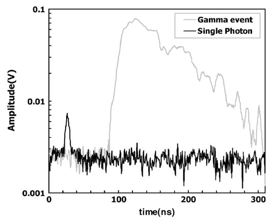
Pulse (gray) due to interaction of a 511 keV γ-ray in a GSO crystal attached to a PMT is shown. The black trace is the pulse due to a single photoelectron generated by a photon from a red LED.
The operation of the OPET detector when both PET and optical photons are present will require a means of distinguishing between the large annihilation events and the weak bioluminescence single photons.
III. Readout Concept
The readout circuit was designed to differentiate between the signals based on the large difference in amplitude between the SPE and γ-ray events. The functional concept is illustrated in Fig. 2. One channel is designed to acquire the SPE events while the other will acquire the γ-ray events. Whenever a γ-ray event is encountered in channel 1, the SPE channel output in channel 2 is suppressed via a veto pulse. The result is that we accept and determine the position for only those SPE events that occur between the large γ-ray events. The voltage threshold on the pulses in channel 1 is set to a larger value than one photoelectron, so that only the γ-ray events are recorded.
Fig. 2.
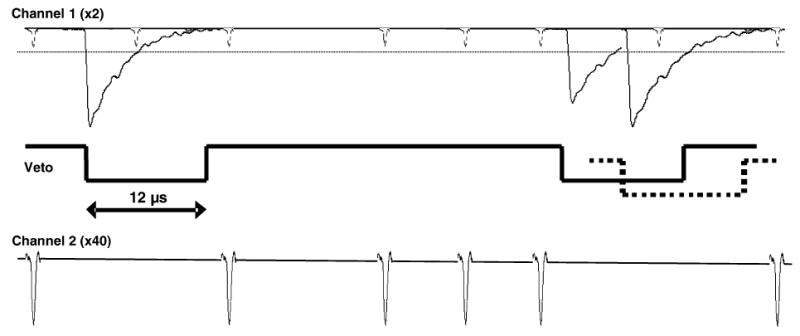
Diagram of the circuit concept used to distinguish between SPE and γ-ray events. Channel 1 has low amplification gain and contains both optical SPE and γ-ray events. A trigger is set just above the SPE level (~10–12 mV, dotted line in channel 1) and is used to suppress (veto) events in channel 2, containing the SPE signal. The dashed line in the middle signal trace indicates a γ-ray event that has randomly occurred before the end of a veto pulse. It extends the veto pulse by retriggering the 12 μs delay.
In order for this circuit to be practical, the veto gate must be long enough to block single photons produced in the tail of the γ-ray events but not so long that large deadtimes are encountered in the SPE readout. For this reason, scintillation crystals with relatively short decay times were investigated. The scintillators LSO and GSO have short decay times of ~40 and ~60 ns, respectively, and should allow a short veto gate. In addition, this type of circuit will only work if the afterglow (phosphorescence) for the scintillation crystal is relatively low, since there would be no direct method to distinguish between these photons and those generated from bioluminescence. Another consideration is the possibility that a second γ-ray event will occur during the time of a veto gate generated by a previous event. In this instance, the veto gate must be retriggered on the late coming pulse and extended to shutdown the SPE channel until after the signal from the second γ-ray event has decayed.
IV. Readout Circuit Implementation
In order to test the readout concept described in the previous section, we constructed a circuit for a single channel PMT. A block diagram schematic of the circuit is shown in Fig. 3. Standard nuclear instrumentation modules (NIMs) were used for all logic and amplifier blocks. After initial amplification, the analog signal from the PMT forms two channels: one with high gain to trigger and digitize the SPE events (the lower channel in Fig. 2) and the other with lower gain to do the same for large pulses generated by the scintillation (γ-ray) events (the upper channel in Fig. 2). The trigger from the large pulses is used to suppress the trigger in the SPE channel so that SPE events are only counted between the large scintillation events.
Fig. 3.
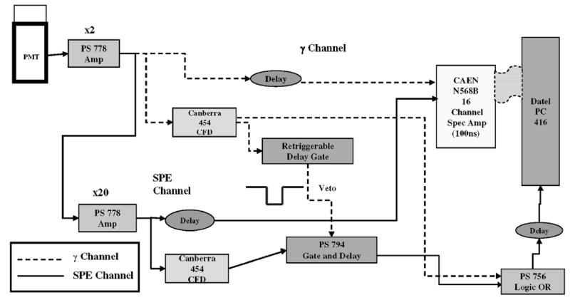
Block diagram of readout circuit used for both multiphoton scintillation pulses and single photoelectrons. Each block corresponds to a NIM module.
The PMT output was amplified by a factor of 40 for the SPE channel and by a factor of two for the γ-ray channel. A veto gate of at least 12 μs duration was required to suppress any SPE events generated during the tail of the scintillation pulse from a 1 cm GSO crystal (Marubeni Specialty Chemicals Inc., White Plains, NY). Initially, a gate-and-delay generator (Phillips Scientific, Mahwah, NJ) was used, but it did not provide a sufficient hold-off time to create this veto. This was replaced by a retriggerable gate that was constructed to extend the veto if γ-ray scintillation events occur while a veto gate is already enabled. The threshold for the veto generated by the scintillation pulses was set just above the voltage of the largest amplitude SPE (~12 mV) so that even very low energy γ-ray events produce a veto gate. Analog signals from both amplifiers were sent to two channels of a 16 channel shaping amplifier (CAEN SpA, Viareggio, Italy) and then digitized by a data acquisition board (DATEL Inc., Mansfield, MA) connected to a PC. A shaping time of 100 ns was used for both channels.
V. Circuit Test
A single channel, Hamamatsu 1463P PMT was coupled to a 1 cm3 GSO scintillation crystal placed next to a 5 μCi 22Na source. The crystal was prepared as previously described and positioned directly on a calibrated red LED light source provided by Xenogen (Xenogen Inc., Alameda, CA). This light source provided a flux of red photons typical of experiments performed with the Xenogen IVIS optical imaging system (3×10⁶ ph/sec into 4π sterradians). The other crystal end was positioned on the PMT face, coupled with optical media.
The optimal length of the veto gate was determined by turning off the LED and measuring the SPE count rate in the presence of the 22Na source. As the veto gate length was decreased from a large value (~50 μs), there was a small but steady increase in background SPE count rate. This was assumed to be due to the thermionic emission of the photocathode and the slight post γ-ray event afterglow of the GSO scintillation crystal. As the veto gate length was reduced, the count rate rose very slowly until the gate length was below about 9 μs where a large increase in the SPE count rate occurred (Fig. 4). These extra SPE counts result from photons produced in the tail of the γ-ray pulse that are not being suppressed by the veto. Consequently, we chose a veto gate length of 12 μs. This surprisingly long time is probably due to the fact that the GSO scintillator has, in addition to the dominant (90%) 30–60 ns decay component, a longer 400–600 ns component [9]. We attempted a similar procedure with a sample of LSO crystal. The inherent radioactivity of the LSO did not pose a problem, because the pulses generated are large compared to SPE pulses and similar to scintillation events from annihilation photons that can be vetoed. However, we found the SPE afterglow of this particular sample of LSO to be extremely high, which rendered it not useful for this application. Large afterglow effects in LSO excited by γ-rays have also been found by others [10].
Fig. 4.
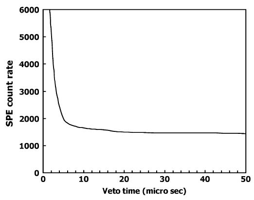
Count rate (c/s) of single photoelectrons observed is plotted versus the length of the veto gate in the presence of γ-ray events. A 1 cm3 GSO crystal was attached to the PMT and a 5 μCi 22Na source placed next to the crystal. The γ-ray event rate was 1700 counts/s.
Even with the relatively long veto pulse that was used, we did not incur excessive deadtimes for the SPE pulses. A high expected singles γ-ray rate is ~10 000 cps during an in vivo study for these PET detector modules. With this count rate and a 12 μs veto, we expect an approximate 12% loss of optical photons, assuming the PET events are distributed evenly in time. If the eventual circuit implementation will be reading individually or with a lower multiplexing factor the 64 channels of the MC-PMT, then the expected scintillation count rate for each channel will be lower and, therefore, the single photon dead-time losses would be reduced.
After determining the veto gate length, we performed measurements with and without the red LED light source while a 5 μCi 22Na source produced a scintillation event rate in the crystal equal to that expected during a typical PET experiment (~4500 cps). The top panel in Fig. 5 shows the measured signal in the SPE channel, with the black trace revealing the typical SPE spectrum. The gray trace in the SPE channel indicates counts acquired due to PMT dark current and afterglow in the GSO scintillator as previously discussed, acquired with the LED source turned off. The bottom panel shows the signal in the scintillation channel. The superimposed black and gray traces indicate that this channel is unaffected by the photons from the LED and that the pulse threshold set as described in Section IV successfully eliminates SPE events. Evident in this spectrum are the 511 keV positron annihilation peak as well as the peak due to the 1275 keV γ-ray emitted by the 22Na source. A more detailed study of the SPE and γ-ray event rates encountered by an OPET prototype detector, which uses the circuit described here, is presented in [6].
Fig. 5.
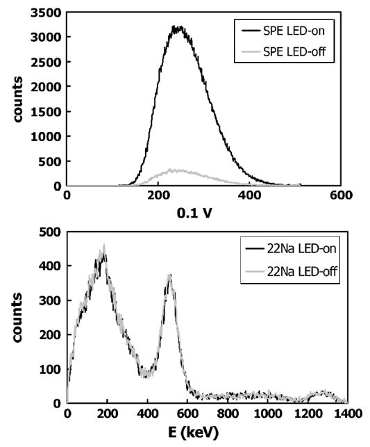
Top panel shows the single photoelectron peak (SPE) obtained on one channel of a digitizer due to the red LED light source (dark curve). The gray curve is the result for this channel when the light source is turned off. The bottom panel shows a simultaneously acquired energy spectrum in the second channel of the digitizer due to γ rays from a 5 μCi 22Na source.
VI. Multichannel PMT Test
After creating and testing the circuit concept with a single channel PMT, we implemented the circuit for a 64-channel MC-PMT and performed tests using the prototype multialkali MC-PMT described in Section II. Such a tube will increase the sensitivity to the bioluminescent SPE events over standard bialkali tubes by a factor of approximately three. The goal of this experiment was to demonstrate that we could not only detect, but also position, the SPE events for an imaging application using a MC-PMT. We expanded the NIM electronics modules previously used to accommodate the four readout outputs [8]. Four SPE and four γ-ray channels were fed to the same 16-channel shaping amplifier and onwards to the digitizer board on the data acquisition PC.
A mask shown in the left hand panel in Fig. 6 was placed on the face of the MC-PMT. A red LED was operated at very low light levels and the image on the right was obtained using the circuit described above. The pattern of the mask is evident in the figure although the upper edge of the image is weaker. From independent tests not reported here, we found that the response of this prototype PMT was nonuniform and particularly weak for red wavelength photons along the upper edge of the photocathode. Results of the tests of this setup with a GSO crystal array and γ-ray source are described in [6].
Fig. 6.
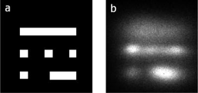
(a) Optical mask placed on a prototype, red-extended, 64 channel MC-PMT. The squares are 2 mm on a side. The large rectangle is 2×12 mm and the small one is 2×6 mm. (b) Image obtained in the presence of a red wavelength LED.
VII. Discussion
While this investigation focused on the feasibility of using this circuit for the OPET application, it concentrated more effort on the sensitivity of the imaging device at the low end of the count rates [11] rather than high count rates. The exact behavior of the readout scheme and in particular the interplay of the veto blocking time with the multiplexing level on the readout board is something that deserves a detailed investigation. The two thresholds used; one for the optical photons and one for the scintillation events, perform well and do not significantly reduce valid qualified events as illustrated in Fig. 5. In practice, this threshold for PET events corresponds to a lower level discriminator of approximately 40 keV. Under typical operation of the OPET detector, the PET events will be discriminated with an energy window having a lower level threshold on the order of 250 to 350 keV. Another practical consideration about this device is that the photodetectors will need to be kept in absolute darkness in between imaging experiments. This is very similar to the method used to operate commercial bioluminescence optical imaging systems. In that case, all system components, including the mouse/specimen holder, need to be constructed from optically inert materials. The proposed OPET device will, therefore, require a cylindrical optical shield/shutter that will block all sensitive optical components like PMTs and scintillator arrays from ambient light in between imaging experiments.
VIII. Conclusion
The electronic circuit that we described allows simultaneous readout of both single photoelectron and scintillation pulses, which differ by more than an order of magnitude in amplitude and time duration. The design is simple and its implementation is relatively straightforward with standard NIM processing electronic modules. While this implementation has limitations that require further investigation when the count rates of the scintillation or the SPE signals become high, it makes possible simultaneous dual modality imaging with the same detector. This circuit concept could be used for other applications in imaging or signal sensing, where analog signals with large amplitude discrepancies need to be detected and quantified. Such large differences in signal size have been encountered by experimenters at the Pierre Auger Cosmic Ray Observatory [12].
IX. Summary
We have developed a circuit capable of imaging photons from bioluminescence while also detecting γ-ray events from positron annihilation. Results from a single channel PMT and a multichannel PMT were shown. This circuit will enable the construction of a dual optical and PET scanner for use in small animal studies which will be capable of simultaneously imaging bioluminescence and PET events.
Acknowledgments
The authors would like to thank Xenogen for helpful discussions. They would also thank Hamamatsu Corporation for providing the prototype MC-PMT and Marubeni crystals for the GSO scintillator.
Footnotes
This work was supported in part by the U.S. Department of Energy under Contract DE-FC03-02ER63420 and in part by the National Institutes of Health under Grants R24 CA 92865 and R01 EB001458.
References
- 1.Massoud TF, Gambhir SS. “Molecular imaging in living subjects: Seeing fundamental biological processes in a new light,”. Genes Develop. 2003;17:545–580. doi: 10.1101/gad.1047403. [DOI] [PubMed] [Google Scholar]
- 2.Luker GD, Sharma V, Pica CM, Dahlheimer JL, Li W, Ochesky J, Ryan CE, Piwnica-Worms H, Piwnica-Worms D. “Noninvasive imaging of protein-protein interactions in living animals,”. PNAS. 2002;99:6961–6966. doi: 10.1073/pnas.092022399. [DOI] [PMC free article] [PubMed] [Google Scholar]
- 3.Ray P, Wu AM, Gambhir SS. “Optical bioluminescence and positron emission tomography imaging of a novel fusion reporter gene in tumor xenografts of living mice,”. Cancer Res. 2003;63:1160–1165. [PubMed] [Google Scholar]
- 4.Celentano L, Laccetti P, Liuzzi R, Mettivier G, Montesi MC, Autiero M, Riccio P, Roberti G, Russo P, Salvatore M. “Preliminary tests of a prototype system for optical and radionuclide imaging in small animals,”. IEEE Trans Nucl Sci. 2003 Oct;50(5):1693–1701. [Google Scholar]
- 5.J. S. Huber, D. Sudar, and W. W. Moses, “Conceptual design of a dual modality optical and radionuclide imaging camera,” presented at the High Resolution Imaging in Small Animals, Rockville, MD, 2001.
- 6.Prout DL, Silverman RW, Chatziioannou A. “Detector concept for OPET—A combined PET and optical imaging system,”. IEEE Trans Nucl Sci. 2004 Jun;51(3):752–756. doi: 10.1109/TNS.2004.829736. [DOI] [PMC free article] [PubMed] [Google Scholar]
- 7.Rice BW, Cable MD, Nelson MB. “In vivo imaging of light-emitting probes,”. J Biomed Opt. 2001;6:432–440. doi: 10.1117/1.1413210. [DOI] [PubMed] [Google Scholar]
- 8.Siegel S, Silverman RW, Yiping S, Cherry SR. “Simple charge division readouts for imaging scintillator arrays using a multi-channel PMT,”. IEEE Trans Nucl Sci. 1996 Jun;43(3):1634–1641. [Google Scholar]
- 9.Takagi K, Fukazawa T. “Cerium-activated Gd SiO single-crystal scintillator,”. Appl Phys Lett. 1983;42:43–45. [Google Scholar]
- 10.Rogers JG, Batty CJ. “Afterglow in LSO and its possible effect on energy resolution,”. IEEE Trans Nucl Sci. 2000 Apr;47(2):438–445. [Google Scholar]
- 11.Su H, Forbes A, Gambhir SS, Braun J. “Quantitation of cell number by a positron emission tomography reporter gene strategy,”. Mol Imag Biol. 2004;6:139–148. doi: 10.1016/j.mibio.2004.02.001. [DOI] [PubMed] [Google Scholar]
- 12.Argiro S, Camin DV, Cattaneo P, Destro M, Fonte R, Gariboldi R, Grassi V, Lapolla M, Manfredi PF, Menichetti E, Nicotra M, Privitera P, Ratti L, Re V, Speziali V, Trapani P. “The analog signal processor of the Auger fluorescence detector prototype,”. Nucl Instrum Mes Phys Res A. 2001;461:440–448. [Google Scholar]


