

Abstract
Optical traps are useful for studying the effects of forces on single molecules. Feedback-based force clamps are often used to maintain a constant load, but the response time of the feedback limits bandwidth and can introduce instability. We developed a novel force clamp that operates without feedback, taking advantage of the anharmonic region of the trapping potential where the differential stiffness vanishes. We demonstrate the utility of such a force clamp by measuring the unfolding of DNA hairpins and the effect of trap stiffness on opening distance and transition rates.
Optical traps (also known as optical tweezers) use light from a tightly focused laser beam to trap small, polarizable objects, such as dielectric beads, in a three-dimensional potential well centered near the focal point [1]. For sufficiently small displacements from equilibrium, the trapping potential is harmonic: The restoring force F varies linearly with the displacement from the trap center x with a constant stiffness k that can be calibrated by several well-established methods. A number of groups have used optical traps in this linear regime to study the properties of important biological systems by attaching single molecules to microscopic beads. Such systems include motor proteins (e.g., kinesin [2], myosin [3], and dynein [4]), processive nucleic acid enzymes (e.g., polymerases [5,6], helicases [7], and exonucleases [8]), and nucleic acid structures [9,10].
For biophysical experiments, a force clamp that fixes the load on the bead (a mechanical analog of the voltage clamp widely used in neuroscience) offers several advantages. The maintenance of constant load facilitates measurement of position by eliminating the need for series elastic corrections to displacement signals [11,12]. Furthermore, constant force avoids complications arising from changes to the potential energy landscape that are generated by molecular motions against a changing load. Techniques such as magnetic tweezers [13] and laminar fluid flow [14] can be used to generate constant force but have been limited in practice to no better than spatial resolution and have, thus far, been unable to match the resolution attained by optical traps.
In optical traps, a force clamp is typically implemented using a feedback system that measures the instantaneous position of the trapped object and then moves the trap to maintain a set displacement between the object and the trap center. Such active force clamps have proven to be powerful tools for biomechanical studies, but they suffer from two inherent limitations. First, the devices used to control the trapping beam (e.g., mechanically driven mirrors or acousto-optic deflectors) can exhibit nonlinear or hysteretic responses, leading to variable loads or feedback instabilities. Second, and more importantly, the finite response time of the feedback loop limits the bandwidth of measurements, typically to less than 1 kHz [15]. These drawbacks make it difficult to use active force clamps with biological systems requiring both high bandwidth and high precision. For example, molecular events such as kinesin steps or short DNA hairpin unfolding occur too rapidly for the feedback system to respond. An innovative system developed by Nambiar et al. [16] addresses these limitations by rapidly line scanning the trapping light while simultaneously modulating its intensity, in such a way as to create a one-dimensional region of constant force extending over several micrometers. This approach eliminates the need for feedback but at the cost of fairly complex instrumentation, limited bandwidth, and greatly reduced trapping force.
Here we introduce a simpler approach that operates passively by taking advantage of the anharmonic region of the trapping potential. As displacement from the center of the trap increases, force initially increases linearly (i.e., constant positive stiffness), then rolls over upon reaching a maximum, and decreases to zero in the region outside the trap [Fig. 1(a)]. Near the peak of the force-displacement (F-x) curve, there exists a region where the force is approximately constant for small displacements (i.e., zero stiffness). An object that is pulled into this region is effectively force clamped, in the sense that the optical force acting on it does not vary with displacement. The load applied by such a force clamp can be set to the desired value simply by adjusting the intensity of the laser light.
FIG. 1.
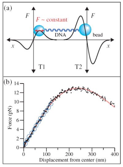
(color). (a) Experimental geometry for the dual trap apparatus (not to scale). Force-displacement (F-x) curves for beads held in the two optical traps are drawn schematically; the beads (blue) are connected by a dsDNA tether. Near the trap center, force rises linearly with displacement; farther out, force rolls over and falls to zero. The beam intensity in T1 is weaker than that in T2, so that at equilibrium the bead in T1 sits at the maximum of its F-x curve, where the stiffness is zero. The bead in T2 remains inside the calibrated linear region, permitting measurement of the applied force. (b) F-x curves for T1. The force is measured in T2 as a function of displacement in T1 (black diamonds) and fit to the derivative of a Gaussian (solid red line). An independent measurement of the F-x curve based on the drag force on an untethered bead (open blue circles) is obtained by moving the microscope stage and sample at predetermined rates while measuring the displacement from the trap center.
Our instrument, an improvement over one described previously [17], uses two 1064 nm trap beams with orthogonal linear polarizations produced by a single Nd:YVO4 laser, whose positions and intensities are controlled independently by acousto-optic deflectors. Two independently positioned 633 nm detector beams with orthogonal polarizations produced by a single HeNe laser measure the positions of objects in the two traps, using position-sensitive detectors that monitor the light scattered by the trapped objects in the back focal plane [18]. The force clamp is implemented as follows: First, one of the two traps [T1 in Fig. 1(a)] is made roughly threefold less intense than the other (T2). Then, by attaching a molecule of double-stranded DNA (dsDNA) between two beads, the bead in the weaker trap (T1) can be pulled out from the center of T1 into the region of constant force (zero stiffness), while the bead in the stronger trap (T2) remains within the calibrated linear region. Displacements at constant force can, thus, be followed in T1 while force is recorded simultaneously in T2.
We measured the F-x curve of T1 using a 550 nm tether of dsDNA, attached at one end by a biotin:avidin linkage to a 600 nm diameter polystyrene bead and at the opposite end by a digoxigenin:antidigoxigenin linkage to a 700 nm diameter polystyrene bead. The displacement of the bead in T1 versus the force measured in T2 is shown in Fig. 1(b). For small displacements, the stiffness is constant, and the nearly linear F-x curve agrees very well with an independent calibration of T1 based on the Stokes drag force for an untethered bead of the same size [1]. For displacements ~240 nm from T1, there is a zone >50 nm wide where force remains constant to within <5%: We use this zero-stiffness region for the force clamp. For positive displacements beyond this zone, the stiffness becomes negative as the force falls toward zero. The measured F-x relation fits well to the derivative of a Gaussian, the shape expected for a Gaussian beam in the paraxial, small-bead approximation [19], and is in qualitative agreement with previous measurements of the nonlinear portion of an optical trap [11].
We note that the measured F-x relationship exhibits significant nonlinearity in the restoring force even for relatively modest displacements from the trap center. From the fit to the F-x curve in Fig. 1(a), we find that the stiffness at x = 50 nm is ~8% less than the stiffness at the center of the trap, while at x = 100 nm it is ~25% less. This deviation represents an important yet generally neglected source of systematic error when using optical traps to make quantitative measurements of force, especially when operating at typical displacements of 50–100 nm or more from the trap center.
We explored the effects of local trap stiffness on measurements of biomolecular motions, including the zero-stiffness force-clamp regime, by studying the mechanically induced unfolding and refolding of short DNA hairpins [9]. A tetraloop hairpin with a 20 basepair (bp), self-complementary stem (sequence: 5′-GAGTCAACGTCTGGATCCTA-T4-TAGGATCCAGACGTTGACTC-3′) was attached to ~1 kb dsDNA “handles” at either end, creating a construct ~550 nm in length. This DNA construct was then linked to beads at each end, as described above. Under ~14 pN of tension, hairpins of this size are bistable, driven by thermal fluctuations between completely folded and fully unfolded states [9]. Measurements of the extension of the hairpin construct when poised near equilibrium (13.6 pN) clearly display two stable positions, corresponding to the closed and open states [Fig. 2(a); data recorded at 10 kHz and median filtered with a 5 ms window]. To measure the opening distance of the hairpin, we constructed histograms of extension and fitted these to two Gaussians, taking the distance between the peaks to represent the opening distance. Note that the width of the Gaussian peaks supplies an estimate of for the spatial resolution of the measurement.
FIG. 2.
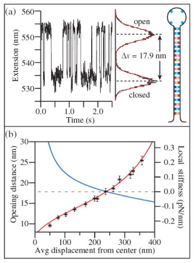
(color). (a) A DNA tetraloop hairpin with 20 bp stem (inset) attached to dsDNA handles is unfolded near equilibrium by a force of ~14 pN. The extension alternates between folded and unfolded states of the hairpin. A histogram of the extension of this hairpin collected over 30 s and fit to two Gaussians (red) shows two peaks separated by an opening distance of 17.9 nm. (b) The change in extension upon hairpin opening (black circles) increases as a function of the average displacement from the trap center as the trap stiffness (blue line) decreases. Data are fit to Eq. (1) (red line), using parameters from the F-x curve in Fig. 1.
Because of the finite compliance associated with the dsDNA handles, the measured change in extension due to unfolding of the hairpin changes as a function of the average position of the bead in trap T1. An intrinsic length change upon unfolding δL produces a corresponding change in extension δx given by
| (1) |
where kDNA is the stiffness of the unfolded hairpin construct and ktraps represents the series stiffness of the two optical traps, 1/ktrap = 1/kT1 + 1/kT2. By tuning the trap power, the hairpin can be unfolded near equilibrium (13.6 pN) at increasing average displacement from T1. The local stiffness decreases, leading to an increase in δx as seen in Fig. 2(b). Note that, for a displacement of ~240 nm from T1, where the differential stiffness drops to zero, the compliance of the dsDNA handles becomes irrelevant, δx ≡ δL, and the expected value of δL for this hairpin, ~18 nm, is fully recovered in the measurement [9,20]. In regions of negative stiffness, δx becomes greater than δL, corresponding to an amplification of the motion [21]. This phenomenon is the mechanical analog of negative differential resistance, which displays similar amplification characteristics. The amplification of displacement does not lead to an improvement in the signal-to-noise ratio, however, because thermal fluctuations are equally amplified [22]. We fit the extension change δx to Eq. (1) using the local trap stiffness calculated from the F-x curve in Fig. 1 (scaled by the trap intensity required to produce a constant unzipping force). Taking the stiffness of the unfolded hairpin construct at the equilibrium unfolding force of 13.6 pN as a free parameter, we find satisfactory agreement with the predicted behavior, assuming a hairpin construct stiffness of 0.2 pN/nm, in line with the stiffness estimated from force-extension curves of the construct (~0.3 pN/nm, data not shown).
Changes in local stiffness can also exert important effects on the apparent rates of hairpin folding and unfolding. The average transition rate at equilibrium, calculated from the lifetimes of the open and closed states, decreases as a function of the displacement from the trap center [Fig. 3(b)]. This occurs because a changing stiffness modifies the energy landscape for the folding/unfolding reaction, as illustrated in Fig. 3(a). The work done on the hairpin by the trap and DNA handles is given by , where F is the force on the hairpin and ξ is the compliance-corrected end-to-end distance of the hairpin (the reaction coordinate). This work is added to the energy landscape of the unloaded hairpin. Qualitatively, for constant force (zero stiffness), W is linear in ξ and, hence, does not change the energy barrier. For positive stiffness, W is superlinear in ξ, lowering the effective energy barrier and increasing the transition rates. For negative stiffness, W is sublinear in ξ, raising the barrier and decreasing the rates.
FIG. 3.
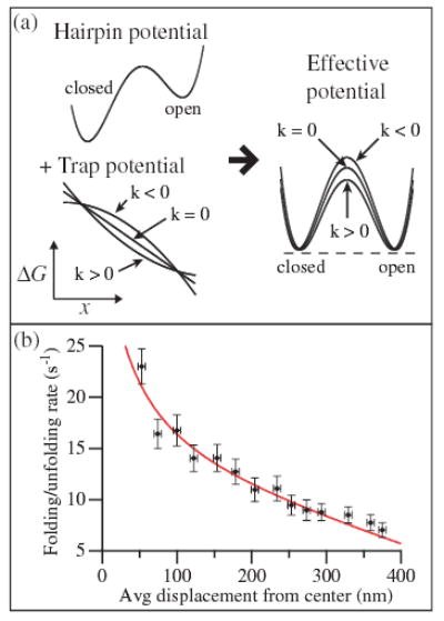
(color online). (a) The presence of the optical trap modifies the potential landscape of the unloaded hairpin, reducing it by the work performed by the trap. Positive effective stiffness of the trap and dsDNA handles reduces the height of the energy barrier, while negative stiffness increases the barrier height. (b) The unfolding/folding rate at equilibrium decreases as a function of the average displacement from the trap center (black circles). The data are fit to Eq. (2) (solid line), using parameters from the F-x curve in Fig. 1.
Quantitatively, we calculate the effect of the trap stiffness on the rates by assuming that the force F on the hairpin during folding/unfolding varies linearly with the reaction coordinate around the equilibrium unfolding force Feq: F(ξ) −Feq = k(ξ − δL/2). Here k is the effective stiffness experienced by the hairpin, consisting of the stiffnesses of the traps and dsDNA handles in series [23]. Integrating this force along the reaction coordinate gives the change in the energy landscape . With a transition state at ξ‡, the folding/unfolding rate r as a function of stiffness is therefore
| (2) |
where r0 is the rate at constant force. We fit the measured rates to this function using the same trap parameters as in Fig. 2, with x‡ as a free parameter. Again, we find good agreement, assuming the transition state is located ~3 nm from the top of the stem. Note that this simple model assumes that motions of the hairpin are communicated instantaneously to the beads and handles. In reality, viscous drag on these two components places a fundamental limit on the response time of the system, which can modify the effective energy landscape experienced by the hairpin. However, an advantage of the passive force clamp is that these effects are decoupled from feedback artifacts, affording an opportunity to resolve the contribution of drag effects to equilibrium behavior by further experimentation.
In addition to the bandwidth limit arising from the relaxation time for the bead/handle attachments, a second practical limitation of the passive force-clamp technique described here is the size of the zero-stiffness region used for the force clamp (~50 nm). While sufficiently large to study the folding/unfolding of small molecules, this region may be too small for the study of processive motors that can move hundreds of nanometers. This difficulty can be overcome fairly simply, however, by using traditional active feedback methods to keep the bead within the zero-stiffness region of the trap as the molecule moves. A constant force is maintained during the feedback-induced motion of the trap as long as the bead remains in the zero-stiffness region.
In summary, we have shown that, by operating an optical trap in the zero-stiffness region of the trapping potential, we can exert a nearly constant force over a useful range of displacements (>50 nm) while achieving very high position resolution. The passive nature of this technique ensures that the force remains invariant during molecular motions of interest, limited only by the viscous relaxation time of the bead and not by the often slower response time of any feedback loop. Studying the mechanical unfolding of DNA hairpins, we find that variations in the local stiffness across an optical trap affect the apparent hairpin extension upon unfolding, due to compliance effects, as well as the unfolding rate at equilibrium, due to changes in the effective energy landscape. By adjusting the trap stiffness appropriately, we can therefore modulate the rates of molecular motions, allowing fast transitions to be slowed down to more easily measured time scales.
Acknowledgments
This work was supported by Grants No. P01-GM066275 and No. R01-GM57035 from the NIH/NIGMS. W. J. G. acknowledges the support of an NSF Graduate Research program.
References
- 1.For a review, see Neuman KC, Block SM.Rev Sci Instrum 752787.2004 [DOI] [PMC free article] [PubMed] [Google Scholar]
- 2.Svoboda K, Schmidt CF, Schnapp BJ, Block SM. Nature (London) 1993;365:721. doi: 10.1038/365721a0. [DOI] [PubMed] [Google Scholar]
- 3.Finer JT, Simmons RM, Spudich JA. Nature (London) 1994;368:113. doi: 10.1038/368113a0. [DOI] [PubMed] [Google Scholar]
- 4.Mallik R, et al. Nature (London) 2004;427:649. doi: 10.1038/nature02293. [DOI] [PubMed] [Google Scholar]
- 5.Yin H, et al. Science. 1995;270:1653. doi: 10.1126/science.270.5242.1653. [DOI] [PubMed] [Google Scholar]
- 6.Wuite GJL, et al. Nature (London) 2000;404:103. [Google Scholar]
- 7.Johnson DS, Patel SS, Wang MD. Perkins TT, et al. Biophys J. ibid. 2004;2004;8686:328A. 1640. [Google Scholar]
- 8.Perkins TT, et al. Science. 2003;301:1914. doi: 10.1126/science.1088047. [DOI] [PMC free article] [PubMed] [Google Scholar]
- 9.Liphardt J, et al. Science. 2001;292:733. doi: 10.1126/science.1058498. [DOI] [PubMed] [Google Scholar]
- 10.Bockelmann U, et al. Biophys J. 2002;82:1537. doi: 10.1016/S0006-3495(02)75506-9. [DOI] [PMC free article] [PubMed] [Google Scholar]
- 11.Simmons RM, Finer JT, Chu S, Spudich JA. Biophys J. 1996;70:1813. doi: 10.1016/S0006-3495(96)79746-1. [DOI] [PMC free article] [PubMed] [Google Scholar]
- 12.Visscher K, Schnitzer M, Block SM. Nature (London) 1999;400:184. doi: 10.1038/22146. [DOI] [PubMed] [Google Scholar]
- 13.Charvin G, Vologodskii A, Bensimon D, Croquette V. Weeks JD, et al. Biophys J. Biophys J. 2005;2005;8888:4124. 2752. doi: 10.1529/biophysj.104.056945. [DOI] [PMC free article] [PubMed] [Google Scholar]
- 14.Davenport RJ, Wuite GJL, Landick R, Bustamante C. Forde NF, et al. van Oijen AM, et al. Science. Proc Natl Acad Sci USA. Science. 2000;2002;2003;28799301:2497. 11–682 , 1235. doi: 10.1126/science.287.5462.2497. [DOI] [PubMed] [Google Scholar]
- 15.Lang MJ, Asbury CL, Shaevitz JW, Block SM. Biophys J. 2002;83:491. doi: 10.1016/S0006-3495(02)75185-0. [DOI] [PMC free article] [PubMed] [Google Scholar]
- 16.Nambiar R, Gajraj A, Meiners JC. Biophys J. 2004;87:1972. doi: 10.1529/biophysj.103.037697. [DOI] [PMC free article] [PubMed] [Google Scholar]
- 17.Shaevitz JW, Abbondanzieri EA, Landick R, Block SM. Nature (London) 2003;426:684. doi: 10.1038/nature02191. [DOI] [PMC free article] [PubMed] [Google Scholar]
- 18.We observe less than 0.5% cross talk between the two detection channels after scattering off of the beads.
- 19.Tlusty T, Meller A, Bar-Ziv R. Phys Rev Lett. 1998;81:1738. [Google Scholar]
- 20.Dessinges MN, et al. Phys Rev Lett. 2002;89:248102. doi: 10.1103/PhysRevLett.89.248102. [DOI] [PubMed] [Google Scholar]
- 21.The bead is stable in the negative stiffness region of the trap as long as the total effective spring constant of the system is positive. This effective spring constant is the series stiffness of trap T2 and the DNA in parallel with the stiffness of trap T1. The bead is thus stably trapped if kT1 > −[kDNAkT2/(kDNA + kT2)].
- 22.Indeed, for large negative stiffness the signal-to-noise ratio appears to be degraded, perhaps due to decreased stiffness in the axial direction of the trap.
- 23.In this approximation, we neglect the compliance contribution of the partially opened hairpin. We take the stiffness of the dsDNA handles, calculated from a wormlike chain model, to be 0.8 pN/nm.