

Abstract
Two methods of temperature control of a dual-beam optical-tweezers system are compared. In the first method, we used a 975 nm infrared laser to raise the temperature 5.6°C/100mW in a nonheating (830 nm) optical trap. The temperature increment logarithmically decreases toward the periphery of the heating beam, causing a fluid convection of 8 μm/s inside a 180 μm thick microchamber. In the second method, heating or cooling fluid was pumped through copper jackets that were placed on the water immersion objectives on both sides of the microchamber to control its temperature from 4.5°C to 68°C. The temperature controlled by the second method was both stable and homogeneous, inducing little fluid convection that would disturb single-molecule applications. An analysis of the power spectrum of the thermal force on a trapped bead showed no detectable vibration due to the liquid circulation. In both methods, force was measured directly by sensors of the momentum flux of light, independent of environmental disturbances including refractive index changes that vary with temperature. The utility of the second method was demonstrated in single-molecule experiments by measuring the mechanical stretch of a 41 kbp λ double-stranded DNA at temperatures ranging from 8.4°C to 45.6°C.
INTRODUCTION
The last decade has seen a burst of activity in the area of single-molecule manipulation (1–4). Among the various instruments available for single-molecule manipulation, optical tweezers have proven to be a powerful tool for biological research because of their versatility, spatial resolution of ∼1 nm, and force sensitivity in the range of 0.1 to hundreds of picoNewtons. These forces are in the same range as those generated by most protein motors or needed to alter the rate or fate of most biochemical reactions (3,5). As a result, several biological systems and processes have been studied using these methods (6–16).
The versatility of the optical tweezers is illustrated by the many reaction conditions they can be adapted to. For example, chemical concentrations and pH can be changed easily and rapidly without affecting the performance of the instrument (17,18), and force can be varied in a systematic way to characterize the thermodynamic and kinetic properties of biological systems (5,19). However, an important experimental parameter, temperature, is difficult to control in the optical tweezers instrument because traditional elements to effect this control are often too bulky to incorporate into the limited working space of the instrument's microchamber. Recent thermomechanical studies on DNA and proteins have revealed that secondary structures of these biomacromolecules, for example, the α helix in protein and the double helix in DNA, become less stable with increasing temperatures (20–23). The detailed description of such thermodynamic and kinetic information can only be obtained by varying the temperature of the system. It is therefore important to develop methods to produce stable and reliable temperature control for optical tweezers.
Williams and co-workers (23) pioneered a method of temperature controls in optical tweezers by using long working distance objectives (∼3 mm), thus creating enough space between the chamber and the objectives to place a Peltier plate to heat or cool the chamber. However, shorter working distance objective lenses with a higher numerical aperture (NA) (1.2 vs. 0.9) enable better spatial resolution and generation of higher optical forces (24). Since the Peltier method seems to require a thick metal piece for proper heat conduction (thus the long working distance and low-NA lenses), we have explored two different methods to control the temperature within the limited confines of a short working distance lens system: 1), a heating infrared laser focused through the microscope objectives, and 2), a water circulation system to heat/cool the objective lenses and the enclosed fluid chamber.
The possibility of using a near-infrared laser as a heat source in microscope experimental systems has been addressed by several groups (25,26). Laser heating has the advantages of being fast, being easily controlled, and having minimal effects on instrumental stability. In 1999, Kato and co-workers focused a Nd:YLF laser (50–100 mW, λ = 1053 nm) on metal particles immersed in water, generating temperatures of 40°C–45°C in areas within 10 μm from the particles (25). These areas reach their equilibrium temperature in milliseconds after the action of the laser, as locally reported with a dye that changes its fluorescence intensity with temperature. Such a “point” source of heat generates a temperature field that falls off as 1/r. Indeed, a steep gradient of 2°C/μm was observed.
Later, Braun and colleagues used a different wavelength laser (λ = 1480 nm) to heat the water directly. Bulk absorption by water creates a line source of heat (see Appendix) whose temperature field falls off as 1/log(r) near the line. A lower temperature gradient of ∼1°C/μm for a temperature increase of 17.7°C/mW at the focus was observed in this case (26). When water is heated locally, a convection circulation is established. Such convection was used by Braun et al. to concentrate a DNA sample by the process of thermophoresis. However, convection can be a nuisance in optical-trap experiments since it brings stray impurities (“dirt”) to the trap and also induces a drag force on the trapped bead, thus complicating force measurement. Furthermore, fluorescent-dye methods for temperature sensing require extra equipment and careful calibration. In the laser-heating experiments described here, we wished to answer the following questions: How much can we increase the temperature at the heating-laser focus? Can we predict the temperature profile from the known geometry and heat conduction of water? How can convection be avoided?
To that end, we modified a dual-beam laser tweezers apparatus (24) by adding a third laser (λ = 975 nm) as a heating source. This apparatus gives a direct measurement of the force exerted on a trapped bead by the change in momentum flux in the trapping light beams due to their interaction with the trapped bead. Since this method does not require force calibration based on trap stiffness, force calibration is independent of environmental disturbances, such as the change of refractive index of a solution due to temperature variation, and therefore has particular advantages in the temperature related studies of laser tweezers. Radiation of 975 nm is more strongly absorbed by water than the trap wavelength of 830 nm. The water absorbance of often-used near-infrared (NIR) wavelengths relative to 830 nm = 1 are as follows: 1064 nm = 4.7, 975 nm = 17, and 1480 nm = 827 (27). We chose 975 nm because it heats water moderately and is readily available as a diode laser. In addition, two studies (28,29) have indicated that 980 nm light is the least damaging of the first three NIR wavelengths to living cells. We therefore wished to characterize its heating effects.
For the second temperature control method, we wished to expand the range of experimental conditions by cooling the sample as well as heating it and to avoid fluid convection by using a delocalized (surrounding) source of heat. To this end, we constructed a water-circulation temperature controller. Due to the limited space between the two objectives in the dual-beam laser setup, copper jackets with internal fluid circulation channels were designed to fit tightly as sleeves of the objectives. Temperature inside the flow chamber was measured by a thermocouple buried inside the chamber and controlled by changing the temperature of the fluid circulating through the jackets. With this design, we addressed the following questions: How uniform is the temperature inside the chamber? What is the effect on the local temperature when fresh buffer flows into the chamber? Does circulation of water through the jackets become a source of vibration noise? How fast can the experimental temperature be changed? Is this temperature control system easy to implement and practical to perform single-molecule experiments at various temperatures?
MATERIALS AND METHODS
Materials
λDNA and XbaI were purchased from New England Biolabs (Beverly, MA). Biotin-dUTP, digoxigenin-dUTP, dTTP, dATP, dCTP, and dGTP were bought from Roche Applied Biosciences (Indianapolis, IN). Oligonucleotides 5′ Cy3-CGCGCGTTTCGGTGATGACGG-3′ (1), and Cy5-CCCATGGTGAAAACGGGGGCG-3′ (2) were prepared by IDT (Coralville, IA). KpnI, T4 DNA ligase, Taq polymerase, and alkaline phosphatase were purchased from Fermantas (Hanover, MD). Streptavidin-coated 2.10 μm diameter polystyrene bead and protein G-coated 2.88 μm diameter polystyrene bead were bought from Spherotech (Libertyville, IL), and the circulator (Haake A81) was bought from Fisher Scientific (Reagent, IN).
Laser-heating method
The optical design includes a dual-counterpropagating-beam optical trap capable of measuring forces as changes in light momentum flux (24) and a “heating” laser (Corning Lasertron CP09750-10-250-G201, 975 nm, 250 mW) whose focus can be moved close to (or away from) the trap. In a momentum-flux sensor, force on the trapped object is sensed as light deflections on position-sensitive detectors. Force calibration is independent of bead size/shape, trap stiffness, or refractive index changes (24). Temperatures at various positions inside the chamber were determined by the following procedure: An arbitrary bead (typically 2 μm diameter silica, but polystyrene can also be used) was trapped in the tweezers. The fluid drag force on that bead was recorded while the chamber was moved back and forth manually using a translation stage (Thorlabs MDT602) and the velocity of the chamber was recorded using an LVDT sensor (Schaevitz PCA 116-100). A drag coefficient for the bead (ξ = F/v) was calculated from force/velocity (F/v) data and compared with Stokes' law (F/v = 6πηa) to obtain the viscosity of the water (η), where the radius of the spherical bead (a) is known. All temperatures were assumed to be ambient when the laser was off, since the temperature of a fluid chamber equilibrates within milliseconds upon laser heating (25). Temperature rise at the trap-bead was calculated from the corresponding viscosity decrease (30). This method of temperature determination is simple to implement when the heating-laser focus is far from the trapped bead but becomes more difficult to use as the foci of the heating and trap beam are increasingly overlapped. When that happens, the heating beam can exert additional force on the trap bead by changes in the momentum of the 975 nm light (refraction), thus adding to the measured fluid-drag force. Therefore any light force from the heating laser must be counted in the fluid-drag measurement. This effect can be achieved by introducing an additional precalibrated photo-detector to measure possible momentum changes in the 975 nm light. Intensity at the heating-laser focus was estimated as the geometric mean ( ) of the power going into the right objective (P1) and the power coming out of the left objective (P2) (24). Each objective passed ∼60% power at 975 nm. Fluid convection inside the chamber was measured by observing the motion of a bead released from the 830 nm trap while keeping the heating-laser focus ∼5 μm away from the bead to avoid trapping it. Temperature and convection measurements were repeated using ordinary water and 99.5%-pure deuterium oxide inside the chamber. “Heavy water” has negligible optical absorption at 975 nm (31).
Circulator heating/cooling method
Circulation setup
The major components of the temperature control module include two copper jackets (Fig. 3 b) that fit as sleeves for the optical tweezers' two objective lenses (Nikon CFI-Plan-Apochromat 60×, NA 1.2, water immersion, working distance ∼320 μm). A circular channel (inner diameter 1/16 inch) through the jacket allowed antifreeze (Dynalene, Whitehall, PA) held at a predetermined, controlled temperature to circulate through the jacket. The center of the jacket was left open to fit the lens of the objective, which stuck out of the surface of the jacket ∼0.015 inch. The jackets did not reduce clearance between the objective lenses and the glass microchamber. To monitor the temperature during the experiment, a thermocouple (K type, 0.005 inch diameter, Omega Engineering, Stamford, CT) was affixed inside the chamber initially some 5 mm away from the optical axis of the lenses. To study the effect of the temperature variation at the surface of the heating jacket on the temperature profile at the laser focal plane between the two objectives, the thermocouple was moved (by moving the entire microchamber) along that plane to measure its temperature.
FIGURE 3.

(a) Schematic drawing of the temperature control element incorporated in the dual-beam laser tweezers system (view from side). Drawing is not to scale. (b) Isometric view of the copper jacket used in a.
Thermal noise measurements
The power spectrum of force fluctuations of an overdamped particle in a harmonic potential is given by (32):
 |
(1) |
where  is the equilibrium spectral density of force fluctuations (in units of force squared per frequency) exerted on the trapped bead, ξ is the drag coefficient of the bead, kB is the Boltzmann constant, and ω is the sampling frequency. The corner frequency, ωc, sets the limit to the rate at which it is practical to sample a process; it is the ratio between the spring constant of the trap, κ, and the drag coefficient of the bead, ξ. For the 2.1 μm diameter beads used in these experiments, ωc is ∼1 kHz.
To perform the power spectrum analysis, a voltage proportional to the force signal was recorded in intervals of 10.5 s at a 100 kHz sampling rate for each temperature. The time interval was then split into 256 parts of 40.96 ms. Next, the Fourier transform of force fluctuations was calculated and averaged over the 256 samples. This procedure was repeated with 10 different beads (mean diameter 2.1 μm) at each temperature to average the effects of bead size deviations and laser power fluctuations. The measurements are valid from 25 Hz to 100 kHz (frequencies higher than 100 kHz could not be measured by the D/A converter used to record the data). At both low and high frequencies, electronic noise may add to the thermal fluctuations, causing deviations from the expected spectrum described by Eq. 1. This was confirmed from the power spectrum taken without the trapped bead (data not shown). The sampling at 100 kHz sets a maximum usable frequency of 50 kHz. The data were fitted to Eq. 1 for frequencies ranging from 200 Hz to 10 kHz.
DNA construct
The DNA construct was made by the method described by Stone and co-workers (14). Briefly, λDNA was circularized and digested with restriction enzymes XbaI and KpnI, which gave three fragments of 41,047 bp, 1503 bp, and 5952 bp. The 41,047 bp fragments were purified using 0.7% agarose Tris-Acetate-EDTA gel. Linkers of the DNA insert were prepared by polymerase chain reaction using pEIB plasmid (966 bp) as template, oligonucleotides 1 and 2 as primers, and a dNTP cocktail containing biotin-dUTP or digoxigenin-dUTP. The modified DNA linker containing biotin-dUTP was digested with KpnI, whereas that containing digoxigenin-dUTP was digested with XbaI. Linkers modified with biotin were dephosphorylated by alkaline phosphatase to produce a nick site in the final DNA construct, which contained the two linkers (∼300 bp with ∼24 biotins and ∼600 bp with ∼48 digoxigenins, respectively) and the 41,047 bp DNA.
Circulation heating/cooling experiment
The experiment was done in a glass microchamber consisting of a channel imprinted into two 90-μm thick pieces of Nescofilm (AZWELL, Inc., Osaka, Japan) that were sandwiched between two No. 1 cover glasses (170 μm each). The total thickness of the resulting chamber was near 540 μm, leaving ∼50 μm free space to form a water meniscus between the chamber and the lens of the water immersion objective. Anti-digoxigenin-coated beads were prepared from protein G-coated beads and cross-linked with dimethyl pimelimidate (33). A tether was formed between a bead on a pipette and a bead in the optical trap (33). The DNA molecule was mechanically extended by moving the chamber relative to the laser trap using a piezo stage. Force was measured by detecting the change in momentum flux in the trapping light beams due to the interaction with the trapped bead. This method does not require force calibration based on trap stiffness and thus excludes environmental disturbances such as the change of refractive index of a solution due to temperature variation (24). All of the DNA stretching experiments were performed using Tris buffer (10 mM Tris, 2 mM EDTA, 500 mM NaCl, pH = 7.5). Power spectrum analysis was performed on 2.1 μm mean diameter polystyrene beads in deionized (DI) water and trapped by two counterpropagating laser beams (wavelength = 830 nm and power = ∼100 mW at focus). A 100 kHz analogue to digital converter was used to record the power spectrum data.
RESULTS
Laser-heating results
Fig. 1 (black data) depicts the temperature profile surrounding a heating-laser focus inside a glass microchamber of 180 μm thickness. Here the 975 nm heating laser was set at medium power (69 mW at focus) and that heating focus was moved to different locations relative to the trapped test bead. For the five distances shown, the temperature rise above ambient (24°C) was determined by the relative decrease in drag coefficient of a single bead (Fig. 1). All measurements were made in the focal plane of the trapping/heating lasers, as per the figure in the Appendix. Error bars were estimated by using the standard deviation of the temperature rise at the focus from three individual experiments. When the power of the heating laser was changed, a linear relation between measured temperature rise and laser power was observed (Fig. 1, red data). The slope of the red-line fit gives a temperature rise of 5.6° per 100 mW at the focus of the heating laser. The same experiments were performed using deuterium oxide instead of water, and no detectable temperature increase was observed using the 975 nm heating laser at any power and zero distance (coincident focus).
FIGURE 1.

Laser-heating results. Black circles represent the temperature measurements obtained by heating the fluid chamber with a 975 nm diode laser at different distances with respect to the trapping lasers position. The black curve displays the theoretical agreement with the logarithmic temperature decay that has been analytically calculated in the Appendix. The red squares correspond to temperatures at the focus of the trapping laser obtained with various powers of the heating laser, whose focus is made coincident with that of the trapping laser. Linear behavior is shown by the regressive red line.
Fig. 2 shows the velocity of water convection observed for three different heating-laser powers (29, 62, and 93 mW at the focus). Convection rates are roughly linear with laser power but are strongly affected by chamber geometry. As microchamber thickness (inside water-layer thickness) was reduced from 180 μm to 90 μm, we observed a fourfold decrease in convection (Fig. 2). No convection was observed at maximum heating power when deuterium oxide was substituted for ordinary water (data not shown). Rather, it became impossible to distinguish possible convection from Brownian motion, even while observing test particles for several minutes.
FIGURE 2.

Convection in chambers of different thickness, expressed as fluid velocity. The small chamber has a thickness of 90 μm, whereas the big chamber has a thickness of 180 μm.
Circulator heating/cooling results
By translating the chamber and attached thermocouple to various locations between the lenses, we found that, in a range of 4.5°C to 68°C, the temperature inside the chamber was uniform (< ±0.1°C) throughout the region (2 mm × 2 mm) surrounding the laser trap. The uniformity of the temperature was also confirmed by the fact that we could not detect any systematic displacement of a 5.0 μm diameter bead in 30 s. Such measurement has a sensitivity limit of 2.4 μm/30 s, which is expected for the bead undergoing a Brownian movement without convection (estimated by 〈x2〉 = 2Dt, where 〈x2〉 is the mean square displacement, D is the diffusion constant of the bead, and t is the time of observation). The temperature inside the chamber was stable, varying < ±0.1°C over a period of hours, and the temperature gradient was small along the direction of the laser beams. In fact, when the temperature was 68°C inside the chamber, it was only 0.8°C higher at the surface of the copper jacket. When a buffer solution at room temperature with a speed of 100 μm/s flowed continuously through the chamber whose buffer temperature was 50°C without flow, the temperature of the flowing buffer inside the chamber was ∼49°C.
To minimize the effect of vibrations due to the circulation pump, the jackets were fit tightly around the objectives, and the circulator was isolated from the optical table. The stability of the circulation system was then tested by power spectrum measurements. Fig. 4 compares the power spectrum of a 2.1 μm polystyrene bead trapped inside the chamber at room temperature with (red) and without (green) circulation. As seen in this figure, the two spectra are identical within experimental error (corner frequency: 1012 Hz and 1026 Hz, respectively), indicating that the effect of fluid circulation through the heating jackets on the system's “noise” is negligible.
FIGURE 4.

Power spectrum density distribution of force fluctuations (expressed in volts squared per Hertz since the voltage measured is proportional to the force) for 2.1 μm mean diameter polystyrene beads trapped in DI water by the dual-beam laser tweezers when (green) the water circulator was not used and (red) the circulator was turned on. Both lasers are 200 mW, 830 nm diode lasers. Only fluctuations in the vertical direction of the trapped bead were measured.
Power spectra of the polystyrene beads trapped in water were also taken at temperatures ranging from 4.5°C to 68°C. Shown in the inset of Fig. 5 is the temperature dependency of the corner frequency of these trapped beads. The corner frequency, ωc, increases with temperature as expected from the inverse dependence of the viscosity, η, of the medium with temperature. Using ξ = 6πηa for the drag coefficient of a bead of radius a, an inverse relationship between the corner frequency and the viscosity, 1/ωc = 6πηa/κ, is obtained. This correlation was indeed observed as shown in Fig. 5, where the linear fitting suggests the trap stiffness, κ, remains constant for different temperatures.
FIGURE 5.

Plot of inverse of corner frequency of the trapped beads (2.1 μm mean diameter) versus viscosity (in micropascal seconds) in DI water. The corner frequency was obtained by fitting the power spectrum density distribution using Eq. 1 (see the text for details). The viscosity of DI water at the corresponding temperature was obtained from the literature (43). (Inset) Plot of corner frequency versus temperature; error bars show the standard deviation of 10 individual experiments. Temperature was measured by a thermocouple fixed inside the chamber.
The stability of the circulation heating-cooling method was estimated as follows: A 3-μm-long DNA molecule was stretched at 8 pN between two trapped beads with fixed distance. After the temperature was set to either 7°C or 37°C for ∼3 h to reach equilibrium, the drifts in the two traps were measured for 10 min at a 10 kHz data rate. A velocity histogram was then made using 0.5 Hz low-pass filtering (34). Average drift velocity of the trap was 0.05 nm/s and average velocity resolution was 0.5 nm/s, the latter of which was estimated from the standard deviation of the Gaussian fits to the histograms. The stability was further tested by making force-extension curves of individual double-stranded DNA molecules. Fig. 6 shows data for three molecules at three temperatures below ambient. Note the overstretching transition at forces above 60 pN, and the end of the overstretch plateau at ∼170% of the B-form contour length. Stretch and release curves are shown in the same color, with minor melting hysteresis visible at the beginning of the plateau. Fig. 7 shows four different molecules stretched at temperatures above ambient. Note large melting hysteresis between stretch and release curves. The melting hysteresis as a function of temperature is plotted in Fig. 8. Note the sharp transition at 35°C.
FIGURE 6.

Force-extension curves of λDNA at low temperatures. Each curve was offset 1 μm to increase the clarity of the figure. Pulling was performed at a constant speed of 1000 nm/s for all three temperatures (8.4°C, 15.2°C, and 21.3°C). Both forward and reverse curves are shown for each temperature. Note the increase of the hysteresis with rising temperature.
FIGURE 7.

Force-extension curves of λDNA at high temperatures (28.1°C, 33.8°C, 37.2°C, and 45.6°C). Pulling was performed at a constant rate of 1000 nm/s. Notice two plateaus are clearly seen at stretching transitions at 37.2°C and 45.6°C. (Dashed red line) Top plateau for curve at 45.6°C. (Dashed black line) Top plateau for curve at 37.2°C. (Dotted red line) Bottom plateau for curve at 45.6°C. (Dotted black line) Bottom plateau for curve at 37.2°C. All curves show major hysteresis with the 45.6°C curve indicating that only single-stranded DNA exists after the transition.
FIGURE 8.

Hysteresis area between stretching and relaxing force-extension curves versus temperature. Error bars represent standard deviation of at least 13 individual experiments at each temperature. Pulling speed was 1000 nm/s.
DISCUSSION
Laser heating
The temperature increase at the focus of a 980 nm laser in water has been previously estimated by Gross (35) to be 5.1° per 100 mW. Our measure of temperature rise at the focus of a 975 nm laser increased with power and gave a slope of 5.6° per 100 mW (Fig. 1), in good agreement with Gross' results. The same temperature rise is predicted analytically from the known NIR absorption and the thermal conductivity of water (see Appendix, Eq. 4a), which also predicts a temperature increase of 1.4°C–1.9°C/100 mW for 1064 nm lasers, consistent with results from Kuo (36) (1.7°C/100 mW) and Liu and co-workers (37) (1.45 ± 0.15°C/100 mW). Convection for the laser-heating system was found to be troublesome for a thick (180 μm) chamber, but it was reduced to velocities below 2 μm/s for a thin (90 μm) chamber. The reduction in the convection is mainly due to the chamber geometry instead of the temperature variation between chambers with different thickness (∼1°C, data not shown). The convection flows yield drag forces <0.1 pN in the thin chamber, a value that is under noise level in the force measurement (∼0.1 pN) of our optical trap.
Our results in deuterium oxide show no temperature rise and no fluid convection even when the heating focus is coincident with the trapped bead. These results are consistent with the negligible absorption of D2O at 975 nm and rule out the possibility that significant heating is caused by the absorption of silica beads at this wavelength.
A significant problem for the heating laser is its limited heating range; the laser system could produce only ∼5° rise at its focus. Presumably the heating range could be improved by using either a higher power 975 nm laser or switching to a 1480 nm laser. Although the convection problem has proved manageable with a 5° temperature rise and a thin chamber, a more powerful laser would make higher temperature gradients and therefore increase convection. For example, a temperature rise of 27°C by a 1480 nm laser at a power of 10 mW (Eq. 4a in Appendix) generates convection speeds of 38 μm/s and 7 μm/s, respectively, for 180 μm and 90 μm thickness chambers (estimated from the linear relationships between the laser power and the temperature in Fig. 1 and the convection speed and the laser power in Fig. 2). These convections produce 1.9 pN and 0.35 pN drag forces, respectively, for a 5 μm diameter bead and thus significantly influence the force measurement in actual experiments. Finally, lasers cannot be used to cool a water-filled microchamber. That task must be performed by Peltier plates or circulation methods.
Circulator heating/cooling
The dual-beam laser tweezers utilized here are capable of trapping a bead >80 μm away from the walls of the chamber, yet the space between the two objectives is <1 mm. These dimensions place severe constraints on the design and dimensions of a temperature control system for this apparatus. Such a temperature control system must be able to establish and maintain the temperature over the whole thickness of the chamber and over an area significantly larger than that occupied by the molecules in the experiment. Although Peltier plates meet most of these requirements, the large size of the metal plates prevents their use in our system. The fluid circulation method, on the other hand, is an excellent alternative to perform all these tasks.
Since the total thickness of a reaction chamber in the dual-beam optical tweezers instrument is ∼500 μm, its heat capacity is significantly smaller along this dimension than in the other dimensions. Controlling the temperature of the chamber, therefore, can be rapidly realized through this dimension of the chamber. For example, when the temperature of the water meniscus between the chamber and objective lenses was changed, the temperature inside the chamber was immediately affected, due to the fast heat exchange between them.
The advantages of this method of temperature control manifested themselves after the copper jackets designed to exchange heat with the chamber through the water meniscus were used as heating/cooling elements. First, the accessible temperature range is wide. In the experiment, values of temperature between 4.5°C and 68°C have been achieved using water as circulating fluid. Second, the temperature inside chamber is both stable and uniform (see Results). The stability of the temperature results from the tight enclosure of the chamber by the two copper jackets and objective lenses, preventing environmental disturbances such as air currents. On the other hand, the uniformity of the temperature is attributed to the high heat conductivity of the copper that makes the circulation jackets (heat source) and the short distance between the heat source and sink (the microchamber). Since the temperature is uniform, it is both possible and practical to measure it inside the chamber by using a thermocouple. Finally, the homogeneous temperature profile prevents the generation of convection currents in the microchamber.
However, there are also disadvantages to the circulation method. For example, although as mentioned above the temperature of the buffer inside the chamber equilibrates fast, the entire system equilibrates and stabilizes slowly (∼20 minutes), generating drifts after each temperature change. In fact, the heat stress felt by the objectives (∼20 μm movement for a 10°C temperature change) requires the realignment of the optics each time a new temperature is set.
To further demonstrate the ability of this temperature control method, we performed single-molecule overstretching experiments on double-stranded DNA (dsDNA) at temperatures ranging from 8.4°C to 45.6°C (Figs. 6 and 7). At temperature below 21°C, overstretch transitions of the DNA are more smooth and reversible than those at higher temperatures. Starting from 33°C, the transition plateau becomes rough and large fragments of dsDNA begin to melt. The amount of the melted DNA, which can be estimated from the hysteresis area of the force-extension curves (22), increases with temperature and undergoes a sharp transition around 35°C (Fig. 8). At 45.6°C, the relaxing force-extension curve follows a single-stranded DNA (ssDNA) trajectory, suggesting all of the dsDNA melts after the overstretch transition. These melted DNA strands did not reanneal at the timescale of our experiment since repeated force-extension curves showed identical ssDNA trajectories.
Hysteresis appears in the relaxation force (relaxation curves, Fig. 7) when the B-form refolding fails to keep pace with the slack given to the molecule by the machine. The hysteresis is consistent with the fraying in the overstretched state (38). Here strands of DNA peel back (fray) from a nick in the DNA during overstretching, without significantly lowering the tension. Those free strands can adopt secondary structures in the form of intrastrand hairpins. When the molecule is relaxed, the external hairpins compete with the main helix and retard its refolding. The sigmoid increase in hysteresis with temperature shown in Fig. 8 could indicate that a sudden onset of fraying occurs at 35°. Such fraying could be caused either by melting of putative S-form DNA (22,38) or by melting of putative B-form cross-links in the overstretched dsDNA (39).
At high temperature, two plateaus were observed in the transition (Fig. 7). The length of these two plateaus is 40% and 60% of that of the entire transition process. This ratio does not change with temperature. Since λDNA has a similar ratio between its d(GC) and d(AT) rich regions, the two plateaus may represent different responses of these two regions when either the B-S or melting transition occurs. Indeed, studies have indicated that with increasing temperatures, the relative stability of d(GC) to d(AT) pairs increases (40). These two plateaus could also originate from the force-induced melting (22,23) and the B-S transition (38) in the overstretched DNA, respectively. Results from Clausen-Schaumann and co-workers (22) are consistent with this scenario since the melting transition they have observed at ∼150 pN disappears at 50°C in their atomic force microscope (AFM) studies. To elucidate the nature of the two plateaus, further studies require DNA constructs with different ratios of d(GC) and d(AT) rich regions.
CONCLUSIONS
We have presented in this article two methods of temperature controls for dual-beam laser tweezers systems using either laser heating or circulation heating/cooling. Compared with the laser-heating method where a 975 nm diode laser was used, the circulation method has advantages of cooling capability, a uniform temperature profile, and no convection inside the chamber. The viability of this method has been demonstrated by measuring the DNA overstretching transition as a function of temperature. The laser method has the ability to produce fast temperature jumps, which could potentially be used to observe changes in the activity of a single molecular motor while the local temperature is changed.
Acknowledgments
Michael Stone is acknowledged for the help in sample preparation.
This research was supported in part by grants from the National Institutes of Health (GM 32543 to C.B. and GM 10840 to I.T.), and U.S. Department of Energy grants DE-AC03-76SF00098 (C.B.), “Microscopies of Molecular Machines” (C.B.), and “Advanced Instrumentations for Microscopies of Molecular Machines” (C.B.). J.R.A.-G. acknowledges a fellowship from the Spanish Secretariat of State for Education and Universities, cofinanced by the European Social Fund.
APPENDIX
Peterman and co-workers (30) presented a model for laser-induced heating in optical traps. In that work, they were interested in describing the temperature at the focus as a function of the trapped bead distance to the coverslips along the propagation Gaussian beam axis. They found that the temperature profile is logarithmic. In our case, we are interested in the temperature profile in the focal plane, which is in the middle of the chamber and parallel to the coverslips. To the best of our knowledge, only Braun and Libchaber (26) have produced a similar experimental pattern. In this Appendix we model this temperature pattern.
After absorption by the water enclosed in a cylindrical surface (Fig. 9, left) that intersects the light cone (Fig. 9, right), the heating-laser light transforms into heat power that propagates radially away from the light-cone axis. A cylindrical surface is truncated at its intersection with the light cone, so that the heat-transfer cylindrical symmetry is exactly kept at the focal plane (provided that the optical power Pin ≈ Pout, see below).
FIGURE 9.

Geometry for the modeling of the temperature profile inside the microchamber due to the heat reradiated after laser absorption by water. See Appendix for details.
The heat power transferred across two infinitesimally separated concentric cylindrical surfaces with radii r and r + dr (Fig. 9, left) is given by (41)
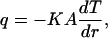 |
(1a) |
where q is the heat power absorbed by water along the distance L of the laser-light path inside the chamber, K is the thermal conductivity of water, A = 2πrL is the surface area of the cylinder, and dT is the temperature difference between the two cylindrical surfaces. By rearranging Eq. 1a and integrating dr, the temperature change between two finitely separated cylindrical surfaces can be obtained in Eq. 2a:
 |
(2a) |
where r′ is the radius of the outside cylinder (r < r′).
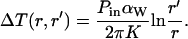
The absorbed power over the distance L is very small (Pout/Pin > 99.99% for L = D, where D is the distance between coverslips, 180 μm). Therefore, by using Lambert-Beer's law, the heat power, q, is given by
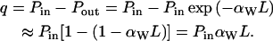 |
(3a) |
Here, αw is the absorption coefficient of water. Using Eqs. 2a and 3a, the temperature rise for a distance r < r′ is given by
 |
(4a) |
For low numerical aperture beams (in our case, NAbeam ≈ 0.5), the radius of the circular section that the light cone projects on the coverslips is given by
 |
(5a) |
where θbeam is the semiangle of the light cone and nw is the refractive index of water.
To estimate the temperature rise at the focus, we assume Tfocus = T(r) (r = 1 μm, i.e., the size of the laser focus at the diffraction limit of λ/(2NAbeam)). The position r′ at which the temperature of the chamber is taken equal to the room temperature, Troom = T(r′), is estimated as follows: the lower limit is set as R (see Eq. 5a), the radius of the laser projection on the coverslips; and the upper limit is D, a value from the best fitting of the experimental data, which coincides with the chamber thickness (see above and Fig. 1).
Therefore, by using r = 1 μm, D/4 < r′ < D (with D = 180 μm), Pin = 69 mW, αw = 0.5 cm−1 (at λ = 980 nm (27) and K = 0.60 W/(m × K) (42)) in Eq. 4a, the temperature rise is
 |
Note that the temperature inside the focal region (r ≤ 1 μm) cannot go to infinity. This implies that the temperature decay inside this region is less than that described by the logarithm. The modeling of the temperature profile inside the focal region is more complicated due to the diffraction limit and the complex (near-field) scattering pattern around the bead. However, an approximate way to describe this region is to consider a cylindrical uniform source of heat with radial size r0 = 1 μm. This yields ΔT(r) ∼1 − (r/r0)2, (r < r0) by solving the heat equation in a cylindrical geometry with a source term (41,42).
When the logarithmic decay outside the focal region (Eq. 4a) is plotted against our experimental data in Fig. 1, a best fitting is obtained with the cutoff distance of r′ = D = 180 μm and the focal region radius of r = 1 μm. Both the logarithmic behavior and the square law profile inside the focal region are consistent with the experimental data obtained by Braun and Libchaber (Fig. 2 e) (26).
References
- 1.Bai, C. L., C. Wang, X. S. Xie, and P. G. Wolynes. 1999. Single molecule physics and chemistry. Proc. Natl. Acad. Sci. USA. 96:11075–11076. [DOI] [PMC free article] [PubMed] [Google Scholar]
- 2.Clausen-Schaumann, H., M. Seitz, R. Krautbauer, and H. E. Gaub. 2000. Force spectroscopy with single bio-molecules. Curr. Opin. Chem. Biol. 4:524–530. [DOI] [PubMed] [Google Scholar]
- 3.Bustamante, C., J. C. Macosko, and G. J. L. Wuite. 2000. Grabbing the cat by the tail: manipulating molecules one by one. Nat. Rev. Mol. Cell Biol. 1:130–136. [DOI] [PubMed] [Google Scholar]
- 4.Gu, L. Q., O. Braha, S. Conlan, S. Cheley, and H. Bayley. 1999. Stochastic sensing of organic analytes by a pore-forming protein containing a molecular adapter. Nature. 398:686–690. [DOI] [PubMed] [Google Scholar]
- 5.Bustamante, C., Y. R. Chemla, N. R. Forde, and D. Izhaky. 2004. Mechanical processes in biochemistry. Annu. Rev. Biochem. 73:705–748. [DOI] [PubMed] [Google Scholar]
- 6.Yin, H., M. D. Wang, K. Svoboda, R. Landick, S. M. Block, and J. Gelles. 1995. Transcription against an applied force. Science. 270:1653–1657. [DOI] [PubMed] [Google Scholar]
- 7.Visscher, K., M. J. Schnitzer, and S. M. Block. 1999. Single kinesin molecules studied with a molecular force clamp. Nature. 400:184–189. [DOI] [PubMed] [Google Scholar]
- 8.Wang, M. D., M. J. Schnitzer, H. Yin, R. Landick, J. Gelles, and S. M. Block. 1998. Force and velocity measured for single molecules of RNA polymerase. Science. 282:902–907. [DOI] [PubMed] [Google Scholar]
- 9.Svoboda, K., and S. M. Block. 1994. Force and velocity measured for single kinesin molecules. Cell. 77:773–784. [DOI] [PubMed] [Google Scholar]
- 10.Smith, D. E., S. J. Tans, S. B. Smith, S. Grimes, D. L. Anderson, and C. Bustamante. 2001. The bacteriophage phi 29 portal motor can package DNA against a large internal force. Nature. 413:748–752. [DOI] [PubMed] [Google Scholar]
- 11.Wuite, G. J. L., S. B. Smith, M. Young, D. Keller, and C. Bustamante. 2000. Single-molecule studies of the effect of template tension on T7 DNA polymerase activity. Nature. 404:103–106. [DOI] [PubMed] [Google Scholar]
- 12.Finer, J. T., R. M. Simmons, and J. A. Spudich. 1994. Single myosin molecule mechanics—piconewton forces and nanometer steps. Nature. 368:113–119. [DOI] [PubMed] [Google Scholar]
- 13.Nishizaka, T., H. Miyata, H. Yoshikawa, S. Ishiwata, and K. Kinosita. 1995. Unbinding force of a single motor molecule of muscle measured using optical tweezers. Nature. 377:251–254. [DOI] [PubMed] [Google Scholar]
- 14.Stone, M. D., Z. Bryant, N. J. Crisona, S. B. Smith, A. Vologodskii, C. Bustamante, and N. R. Cozzarelli. 2003. Chirality sensing by Escherichia coli topoisomerase IV and the mechanism of type II topoisomerases. Proc. Natl. Acad. Sci. USA. 100:8654–8659. [DOI] [PMC free article] [PubMed] [Google Scholar]
- 15.Forde, N. R., D. Izhaky, G. R. Woodcock, G. J. L. Wuite, and C. Bustamante. 2002. Using mechanical force to probe the mechanism of pausing and arrest during continuous elongation by Escherichia coli RNA polymerase. Proc. Natl. Acad. Sci. USA. 99:11682–11687. [DOI] [PMC free article] [PubMed] [Google Scholar]
- 16.Brower-Toland, B., and M. D. Wang. 2004. Use of optical trapping techniques to study single nucleosome dynamics. Methods Enzymol. 376:62–72. [DOI] [PubMed] [Google Scholar]
- 17.Baumann, C. G., S. B. Smith, V. A. Bloomfield, and C. Bustamante. 1997. Ionic effects on the elasticity of single DNA molecules. Proc. Natl. Acad. Sci. USA. 94:6185–6190. [DOI] [PMC free article] [PubMed] [Google Scholar]
- 18.Williams, M. C., J. R. Wenner, L. Rouzina, and V. A. Bloomfield. 2001. Effect of pH on the overstretching transition of double-stranded DNA: evidence of force-induced DNA melting. Biophys. J. 80:874–881. [DOI] [PMC free article] [PubMed] [Google Scholar]
- 19.Tinoco, I., and C. Bustamante. 2002. The effect of force on thermodynamics and kinetics of single molecule reactions. Biophys. Chem. 101:513–533. [DOI] [PubMed] [Google Scholar]
- 20.Law, R., G. Liao, S. Harper, G. Yang, D. W. Speicher, and D. E. Discher. 2003. Pathway shifts and thermal softening in temperature-coupled forced unfolding of spectrin domains. Biophys. J. 85:3286–3293. [DOI] [PMC free article] [PubMed] [Google Scholar]
- 21.Janovjak, H., M. Kessler, D. Oesterhelt, H. Gaub, and D. J. Müller. 2003. Unfolding pathways of native bacteriorhodopsin depend on temperature. EMBO J. 22:5220–5229. [DOI] [PMC free article] [PubMed] [Google Scholar]
- 22.Clausen-Schaumann, H., M. Rief, C. Tolksdorf, and H. Gaub. 2000. Mechanical stability of single DNA molecules. Biophys. J. 78:1997–2007. [DOI] [PMC free article] [PubMed] [Google Scholar]
- 23.Williams, M. C., J. R. Wenner, I. Rouzina, and V. A. Bloomfield. 2001. Entropy and heat capacity of DNA melting from temperature dependence of single molecule stretching. Biophys. J. 80:1932–1939. [DOI] [PMC free article] [PubMed] [Google Scholar]
- 24.Smith, S. B., Y. J. Cui, and C. Bustamante. 2003. Optical-trap force transducer that operates by direct measurement of light momentum. Methods Enzymol. 361:134–162. [DOI] [PubMed] [Google Scholar]
- 25.Kato, H., T. Nishizaka, T. Iga, K. J. Kinosita, and S. Ishiwata. 1999. Imaging of thermal activation of actomyosin motors. Proc. Natl. Acad. Sci. USA. 96:9602–9606. [DOI] [PMC free article] [PubMed] [Google Scholar]
- 26.Braun, D., and A. Libchaber. 2002. Trapping of DNA by thermophoretic depletion and convection. Phys. Rev. Lett. 89:188103. [DOI] [PubMed] [Google Scholar]
- 27.Palmer, K. F., and D. Williams. 1974. Optical properties of water in near infrared. J. Opt. Soc. Am. 64:1107–1110. [Google Scholar]
- 28.Liang, H., K. T. Vu, P. Krishnan, T. C. Trang, D. Shin, S. Kimel, and M. W. Berns. 1996. Wavelength dependence of cell cloning efficiency after optical trapping. Biophys. J. 70:1529–1533. [DOI] [PMC free article] [PubMed] [Google Scholar]
- 29.Neuman, K. C., E. H. Chadd, G. F. Liou, K. Bergman, and S. M. Block. 1999. Characterization of photodamage to Escherichia coli in optical traps. Biophys. J. 77:2856–2863. [DOI] [PMC free article] [PubMed] [Google Scholar]
- 30.Peterman, E. J. G., F. Gittes, and C. F. Schmidt. 2003. Laser-induced heating in optical traps. Biophys. J. 84:1308–1316. [DOI] [PMC free article] [PubMed] [Google Scholar]
- 31.Braun, L. C., and S. N. Smirnov. 1993. Why is water blue? J. Chem. Educ. 70:612–614. [Google Scholar]
- 32.Wang, M. C., and G. E. Uhlenbeck. 1945. On the theory of the Brownian motion II. Rev. Mod. Phys. 17:323–341. [Google Scholar]
- 33.Liphardt, J., B. Onoa, S. B. Smith, I. Tinoco, and C. Bustamante. 2001. Reversible unfolding of single RNA molecules by mechanical force. Science. 292:733–737. [DOI] [PubMed] [Google Scholar]
- 34.Adelman, K., A. La Porta, T. J. Santangelo, J. T. Lis, J. W. Roberts, and M. D. Wang. 2002. Single molecule analysis of RNA polymerase elongation reveals uniform kinetic behavior. Proc. Natl. Acad. Sci. USA. 99:13538–13543. [DOI] [PMC free article] [PubMed] [Google Scholar]
- 35.Gross, S. P. 2003. Application of optical traps in vivo. Methods Enzymol. 361:162–174. [DOI] [PubMed] [Google Scholar]
- 36.Kuo, S. C. 1998. A simple assay for local heating by optical tweezers. Methods Cell Biol. 55:43–45. [DOI] [PubMed] [Google Scholar]
- 37.Liu, Y., D. K. Cheng, G. J. Sonek, M. W. Berns, C. F. Chapman, and B. J. Tromberg. 1995. Evidence for localized cell heating induced by infrared optical tweezers. Biophys. J. 68:2137–2144. [DOI] [PMC free article] [PubMed] [Google Scholar]
- 38.Smith, S. B., Y. J. Cui, and C. Bustamante. 1996. Overstretching B-DNA: the elastic response of individual double-stranded and single-stranded DNA molecules. Science. 271:795–799. [DOI] [PubMed] [Google Scholar]
- 39.Wenner, J. R., M. C. Williams, I. Rouzina, and V. A. Bloomfield. 2002. Salt dependence of the elasticity and overstretching transition of single DNA molecules. Biophys. J. 82:3160–3169. [DOI] [PMC free article] [PubMed] [Google Scholar]
- 40.Chen, Y. Z., and E. W. Prohofsky. 1996. Sequence and temperature effect on hydrogen bond disruption in DNA determined by a statistical analysis. Eur. Biophys. J. 25:9–18. [DOI] [PubMed] [Google Scholar]
- 41.Incropera, F. P., and D. P. DeWitt. 2002. Fundamentals of Heat and Mass Transfer. John Wiley & Sons, New York.
- 42.Weast, R. C., editor. 1973. CRC Handbook of Chemistry and Physics, 53rd ed. CRC Press, Boca Raton, FL.
- 43.Sengers, J. V., and J. T. R. Watson. 1986. Improved international formulations for the viscosity and thermal-conductivity of water substance. J. Phys. Chem. Ref. Data. 15:1291–1314. [Google Scholar]