Abstract
Tethered membranes have been proven during recent years to be a powerful and flexible biomimetic platform. We reported in a previous article on the design of a new architecture based on the self-assembly of a thiolipid on ultrasmooth gold substrates, which shows extremely good electrical sealing properties as well as functionality of a bilayer membrane. Here, we describe the synthesis of lipids for a more modular design and the adaptation of the linker part to silane chemistry. We were able to form a functional tethered bilayer lipid membrane with good electrical sealing properties covering a silicon oxide surface. We demonstrate the functional incorporation of the ion carrier valinomycin and of the ion channel gramicidin.
INTRODUCTION
Solid supported membrane systems were used in the last decade in a variety of ways to mimic properties of a natural membrane (1–5). Different approaches have been used by either creating a bilayer directly on a surface or using polymer cushions or protein layers as spacers. The investigated surfaces were either glass/silicon substrates or metal electrodes (e.g., gold). The advantage of using a spacer between substrate and bilayer is the fact that this construct provides an ionic reservoir underneath the membrane and avoids direct contact of embedded membrane proteins with the substrate. Previous assemblies often could not provide sufficiently good electrical sealing properties, an essential criterion for the study of ion transport processes mediated by membrane proteins. The concept of tethered bilayer lipid membranes (tBLMs), where the proximal part of the bilayer membrane is covalently attached to a surface via a spacer unit, has been shown to provide membrane systems with good electrical properties as well as with increased stability (6–9).
Recently, we developed a promising system with good electrical sealing properties. Due to high electrical resistance of the membrane, several membrane proteins were successfully incorporated and characterized in a functional form (6,10–12). For biosensing applications, it is interesting to combine the biological system of a membrane with a (micro-)electronic read-out system. These systems are mostly based on silicon technology. For example, the simplest gate structure of a nonmetallized field-effect transistor for operation in electrolytes consists of a thin layer of silicon oxide. So far, transistors have been used to study membrane-related processes by attaching giant vesicles to the transistor (13) or by fusion of vesicles to a silicon oxide substrate (14). We aimed to construct a tBLM on a silicon oxide surface based on the archaeal lipid analog used previously on gold substrates, by transforming the anchor chemistry from a thiol to a silane. A tethered self-assembled monolayer (SAM) was formed by self-assembly on silicon oxide surfaces. Vesicles were then fused to complete the assembly to an electrically sealing bilayer.
The high resistance of the SAM allowed the electrical verification of the functional incorporation of membrane proteins. We have been able to incorporate both the ion carrier peptide valinomycin and the well-known antibiotic model pore gramicidin. Functionality of both molecules has been shown by a decrease of the membrane resistance upon incorporation. The concentration dependence and ion selectivity of both valinomycin and gramicidin were demonstrated. These systems have been studied in detail before; however, they have been incorporated either in mechanically instable black lipid membranes or in supported membranes with, in most cases, much lower membrane resistances (15–18).
SYNTHESIS AND IMMOBILIZATION OF DPTTC AND DPTDC
The tBLMs presented here are based on two molecules: the archaeal analog lipid 2,3-di-O-phytanyl-sn-glycerol-1-tetraethylene glycol-(3-trichloropropyl-silane) ether lipid (DPTTC) and 2,3-di-O-phytanyl-sn-glycerol-1-tetraethylene glycol-(3-chloro-dimethylpropyl-silane) ether lipid (DPTDC). The detailed synthesis and characterization of the entire lipids will be described elsewhere.
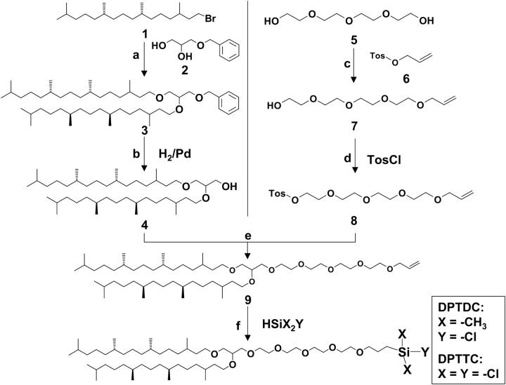
The basic synthetic route is depicted in Scheme 1. The lipids utilized in this study have two phytanyl chains connected to the tetra(ethylene glycol) tethered spacer via a glycerol unit. Phytanyl chains were chosen as hydrophobic tails instead of alkyl chains because of their low phase-transition temperature and their influence on the density and stability of biological membranes (8,19). Furthermore, the 2,3-di-O-phytanyl-sn-glycerol unit contains only ether linkages to prevent hydrolytic cleavage (20). This moiety is known to form stable biomembranes under the extreme living conditions (e.g., high temperatures) of extremophiles or archaea (21).
SCHEME 1.
Synthesis of DPTDC and DPTTC: phytanbromid 1 was synthesized from phytol according to (36,37), a), (±)-3-benzyloxy-1,2-propanediol 2 (1 equiv), NaH (3.1 equiv), phytanbromid 1 (3 equiv), THF, 40°C, 6 d, 86%; b), this step was carried out according to a procedure described elsewhere (7); c), tetraethylene glycol 5 (2 equiv), allyl p-toluenesulfonate 6 (1 equiv), NaH (3 equiv), THF, 45°C, 3 d, 76%; d), p-toluenesulfonyl chloride (2 equiv), NaH (1.5 equiv), TEA (1 equiv), THF, 30°C, 2 d, 77%; e), 4 (1 equiv), 8 (1 equiv), NaH (1.2 equiv), THF, 40°C, 2 d, 62%; and f) X = CH3, Y = Cl (DPTDC): dimethylchlorosilane, H2PtCl6—catalyst, Ar, RT, 6 h, 75%; X = Y = Cl (DPTTC): trichlorosilane, H2PdCl6—catalyst, Ar, RT, 3 h, 88%.
The choice of the tethering moiety is based on the criteria it has to fulfill: it should be hydrophilic and should not interact either with membrane lipids or with membrane proteins. For the robustness required in practical applications, it should also be chemically linked to the bilayer at one end and to the solid substrate (silicon wafer) at the other end. Furthermore, it should not engage in extensive physical interactions with the surface. Tetra(ethylene glycol) is likely to fulfill these requirements—it is known to prevent nonspecific adsorption of proteins to surfaces (22–24), does not absorb to the lipid bilayer surfaces (25), and interacts only minimally with quartz and glass surfaces (26).
DPTTC and DPTDC are immobilized on SiOx surfaces by immersing the substrate into a dilute (typically 2–40 mM) solution of either DPTTC or DPTDC in dry toluene. A few drops of dry Et3N are added to quench the coproduct HCl and to promote the reaction (27,28). It should be emphasized that the difference between immobilization procedures of both lipids occurs within a thin water layer adsorbed to the substrate. This is required in the case of DPTTC. In the case of DPTDC, the covalent binding between the lipid and the substrate occurs after a condensation reaction of the monochlorosilane anchor group with the hydroxyl groups available on the silicon-oxide surface. In contrast, the commonly assumed mechanism for a trichloropropyl-silane anchor group as in DPTTC consists of three distinct phases: 1), the trichlorosilane groups are hydrolyzed by the water layer on the substrate surface, 2), the chains are then bound via hydrogen bonds to the surface and to their neighbors, and 3), this (unstable) situation is followed by water elimination leading to a network in which each lipid is linked to the surface and to the neighbors (Fig. 1) (29). However, one should notice that the image in Fig. 1 is idealized. In fact, the data presented in this work suggest that the actual packing density is less dense and that the layer is thinner than suggested by the figure.
FIGURE 1.
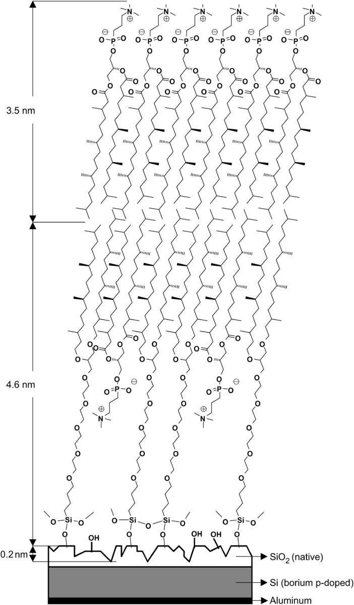
Schematic representation of the arrangement of the DPTTC and DPhyPC molecules forming a tBLM. The picture is somewhat idealized. The packing of the tethered SAMs is most probably less dense.
METHODS AND MATERIALS
Chemicals
(±)-3-Benzyloxy-1,2-propanediol 2, tetraethylene glycol 5, and allyl p-toluenesulfonate 6 (all purchased from Fluka, Buchs, Switzerland) were dried over molecular sieve A3. Triethylamine (TEA, Acros, Geel, Belgium) and tetrahydrofuran (Fisher, Fair Lawn, NJ) were dried over CaH2 and potassium, respectively. Trichlorosilane (Acros) and chlorodimethylsilane (Lancaster, Morecambe, UK) were distilled before use. 1,2-Di-O-phytanoyl-sn-glycero-3-phosphocholine (DPhyPC, Avanti Polar Lipids, Alabaster, AL), valinomycin (Fluka), gramicidin D (Bacillus brevis, Sigma, St. Louis, MO), potassium chloride, sodium chloride, tetramethylammonium chloride (Acros), p-toluenesulfonyl chloride (TosCl, Acros), platinum on activated charcoal (Pt/C, Fluka), hexachloroplatinic acid (H2PtCl6, Fluka), sodium hydride (NaH, Aldrich, St. Louis, MO), and toluene (Acros, water < 30 ppm) were used as received.
Substrates
We used highly p-doped silicon wafers (diameter 3″, orientation 〈100〉, boron-doped 0.005–0.002 Ωcm) to fabricate the electrolyte-insulator-semiconductor chips. High doping is favorable because it increases the threshold voltage of the electron inversion layer, which acts as an interfering capacitance in the electrochemical impedance spectroscopy (EIS) experiments. Accordingly, we did not oxidize the wafer further but retained the native oxide layer. A thin oxide layer has a high capacitance, which ensures that the measured impedance is dominated by the smaller capacitance of the bilayer in series (14). The backside contact is made by evaporation of 250 nm aluminium followed by a temper step (N2, 400°C, 10 min). Finally, the wafers were cut into squares of 9 mm × 9 mm to fit the experimental set up.
Cleaning procedure
Before use, the Si wafers were cleaned thoroughly to increase the surface coverage of OH groups on their surface. A typical cleaning procedure was ultrasonification (US) in pure water (MilliQ, R > 18 MΩ cm) for 10 min, US in a 1:1 mixture of acetone:ethanol for 10 min, 300 W plasma cleaning (0.9 mbar argon/0.1 mbar oxygen) for 5 min, and US in MilliQ for 10 min. If necessary, the samples were stored in MilliQ. After such a cleaning procedure, the water contact angle was below 10°, the thickness of the oxide layer as determined by ellipsometry was 18 ± 5 Å, and the root mean-square roughness determined by atomic force microscopy (AFM) was 2.0 ± 0.5 Å (from a 5 μm × 5 μm area, roughness from features smaller than 10 nm is probably not resolved by the AFM tip).
Electrochemical impedance spectroscopy
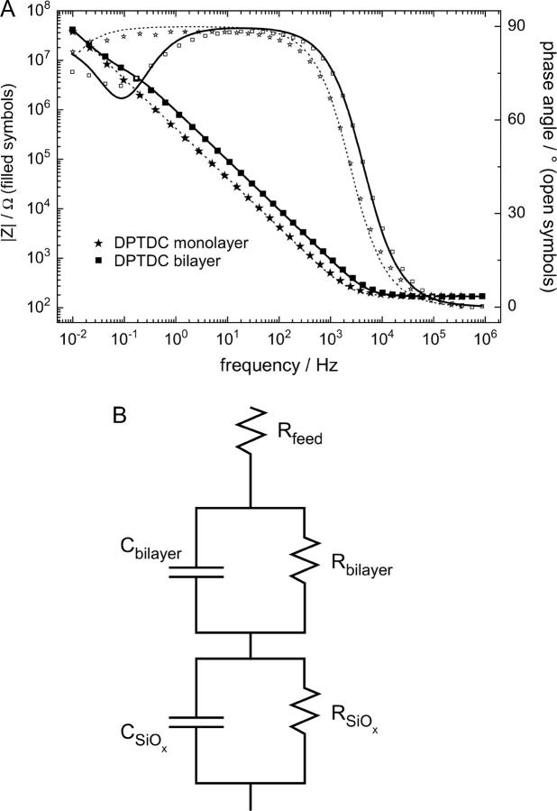
Electrochemical impedance spectroscopy (EIS) measurements were conducted using an IM6 spectrometer from Zahner Electrics (Hannover, Germany). Spectra were recorded for frequencies between 10 mHz and 1 MHz at 0 V potential with an AC modulation amplitude of 10 mV. Raw data were analyzed using the ZVIEW software package (version 2.70, Scribner Associates, Southern Pines, NC). Standard three electrode measurements were performed in Teflon cells with the substrates as the working electrode, a coiled platinum wire as the counter electrode, and a DRIREF-2 reference electrode (World Precision Instruments, Sarasota, FL). The home-built Teflon cells have a buffer volume of 0.5 ml and an electrochemically open area on the substrates of 0.385 cm2. The data were fitted using an equivalent circuit consisting of a feed resistance and two RC elements (a resistance connected in parallel to a capacitance) in series (see Fig. 3 B). The fitted values are normalized to the electrode surface area.
FIGURE 3.
(A) Bode plot of the EIS of a DPTDC monolayer (★) and the same sample after 1 day of vesicle fusion (▪). Lines correspond to a fit using an equivalent circuit of a feed resistance in series with an RC element of the bilayer in series with an RC element of the SiOX layer. (B) The fit to the measurement after vesicle fusion (solid line in A) yields RSiOx = 26.7 MΩ, CSiOx = 1.02 μF, Rbilayer = 1.56 MΩ, Cbilayer = 735 nF. Only one RC element representing the oxide layer with the attached SAM has been used to fit the substrate before vesicle fusion (dotted line in A): R = 88.5 MΩ, C = 987 nF.
Atomic force microscopy
The samples were scanned with a Dimension 3100 model (Veeco, Santa Barbara, CA) under ambient conditions. Single beam silicon cantilevers (Olympus OMCL-AC160TS-W2 TappingMode) with spring constants of ∼45 N/m and resonant frequencies of ∼300 kHz have been used. The roughness is determined from topographs recorded in tapping mode.
Ellipsometry
Ellipsometric measurements were carried out using an EP3 imaging ellipsometer from Nanofilm (Göttingen, Germany) with a λ = 532 nm laser source. The angle of incidence was 70° for measurements in air, 60° for measurements in a fluid cell. Thickness values were fitted with the EP3View V2.01 software using a layer model with the following parameters: n = 4.17 and k = 0.049 for Si, n = 1.4605 and k = 0 for SiOx, n = 1.50 and k = 0 for the self-assembled monolayers (SAM), and n = 1.45 and k = 0 for the bilayer (6). SAM thicknesses were determined by comparing results before and after the growth of the layer.
Immobilization of DPTDC on SiOx surfaces (SAM preparation)
DPTDC was immobilized on the SiOx surface of a silicon wafer at room temperature from toluene solutions using Et3N as promoter and acid scavenger. The substrates were dried by vacuum firing and immersed in an assembly solution. The SAMs were typically assembled within 24 h. The samples were then cleaned by rinsing extensively and ultrasonified 5 min in toluene, toluene:ethanol = 1:1 and ethanol, followed by rinsing with chloroform.
Immobilization of DPTTC on SiOx surfaces (SAM preparation)
The procedure is essentially the same as for DPTDC, except that the silicon wafers were not dried before assembly (a water layer on the substrate surface is required).
Vesicle fusion (tBLM and sBLM preparation)
Bilayers were grown on the substrates by insertion of 0.2 mM DPhyPC (1,2-diphytanoyl-sn-glycero-3-phosphocholine) vesicles (50 nm Ø by extrusion in MilliQ) into the electrochemical cells with a buffer of typically 100 mM KCl. For tBLM preparations, substrates previously treated with DPTDC and DPTTC were used. Supported bilayer lipid membranes (sBLM) were assembled by using cleaned but untreated substrates where the vesicles directly interact with the hydrophilic silicon oxide layer.
Incorporation of valinomycin and gramicidin
Valinomycin and gramicidin were dissolved in ethanol (2 mg/ml and 5 ng/ml, respectively) and added to the preformed bilayer. Incorporation was allowed for 1 h. The final concentration of valinomycin in the cell was 18 μM, the concentration of gramicidin was varied as described below between 20 and 1000 nM.
RESULTS AND DISCUSSION
Immobilization of DPTDC and DPTTC on SiOx surfaces
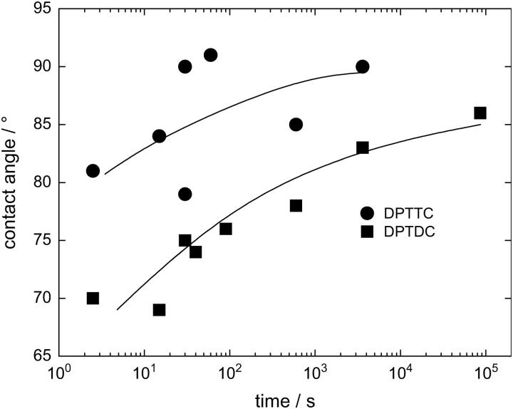
Substrates treated with DPTDC and DPTTC for 1 day as described above have advancing water contact angles of 86° ± 4° and 91° ± 5°, respectively, and receding water contact angles of 59° ± 3° and 66° ± 4°, respectively. The timescale of the immobilization can be seen in Fig. 2. Average thicknesses of the SAM as determined by ellipsometry are 1.3 nm ± 0.5 nm for DPTDC and 1.8 nm ± 0.6 nm for DPTTC, which has to be compared to the calculated molecular length of 4.6 nm (Fig. 1). AFM topographs show a slightly rougher surface of the substrate than before deposition of the monolayer, but the film is homogeneous and no structures like islands can be observed (AFM data not shown). EIS of the samples before and after immobilization showed a ∼20% decrease of the capacitance of the oxide layer due to the additional thickness of the SAM.
FIGURE 2.
Advancing water contact angles of substrates treated for different lengths of time with DPTTC (•) and DPTDC (▪) for different assembly times. The lines are guides to the eye.
From the strong increase of the contact angle, we suggest that a thin first layer of molecules is bound to the silicon oxide surface. The molecules, however, are not closely packed to form a densely packed monolayer but seem to form a rather diluted film, which can be presumed from the undersized film thickness as determined by ellipsometry as well as from the difference between advancing and receding contact angles.
Growth and electrochemical properties of the lipid bilayer
Impedance spectra of the substrates with an attached SAM can be analyzed by an equivalent electrical circuit consisting of a feed resistance and an RC element (a resistance connected in parallel to a capacitance) describing the oxide/SAM layer. After vesicle insertion, a second RC element forms within a few hours with a rapid drop in capacitance and a steady increase in resistance. The bilayer formation is usually completed within 24 h as determined from a saturation of the bilayer resistance. The two RC elements corresponding to the oxide layer and the tethered bilayer, respectively, can be easily distinguished in the combined impedance and phase Bode plot is shown in Fig. 3 A. The logarithm of the absolute value of the impedance (left ordinate) and the phase angle (nonlogarithmic, right ordinate) are plotted versus the logarithmic AC modulation frequency. In such a log-log plot, resistively dominated frequency regions are horizontal with zero phase and capacitive dominated frequency regions have a slope of −1 and are out of phase by 90°, with higher capacitance shifting the curve to lower frequencies. Accordingly, the measurement after bilayer growth reveals a flat impedance with low phase at high frequencies (>10 kHz) where the solution resistance dominates the current response, a rising impedance of slope −1 and out of phase in the broad midfrequency region where the capacitance of the oxide layer and the bilayer in series dominate, and the low frequency region (<0.1 Hz) where only the capacitance of the oxide layer persists. The last two regions are separated by a transition shoulder region with lower phase which manifests the resistance of the bilayer. The data can be fitted with good agreement using the equivalent circuit shown in Fig. 3 B.
The average bilayer resistances and capacitances, determined from 10 different samples, are 1.45 ± 1.06 MΩ cm2 and 888 ± 36 nF cm−2 for DPTDC, and 0.5 ± 0.3 MΩ cm2 and 782 ± 26 nF cm−2 for DPTTC, respectively. The bilayers are stable over more than a week and are robust upon rinsing.
Compared to supported bilayers, where bilayer resistances were usually lower by more that one order of magnitude, the relatively high bilayer resistances of ∼1 MΩ cm2 in the case of the tBLM architectures suggest a partial filling of the lightly packed proximal bilayer leaflet by lipids from the vesicles.
The difference between the two systems (DPTDC and DPTTC) can be explained with a different monolayer structure or packing density as can be seen from the different hydrophobic character of the surface (Fig. 2). However, both systems show reasonably good electrical sealing properties to be used as a biomimetic membrane.
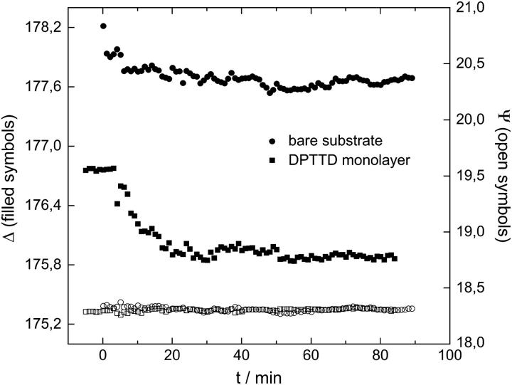
We also studied the kinetics of the bilayer formation by ellipsometry using a liquid cell filled with MilliQ water. The growth of the bilayer after vesicle insertion on a bare substrate and on a DPTTC covered substrate can be compared in Fig. 4. The drop in Δ is more pronounced for the SAM covered sample corresponding to an overall thicker bilayer system. A simple layer model assuming a constant refractive index of n = 1.45 for the whole bilayer system yields a bilayer thickness of ∼2 nm for the supported bilayer and ∼4 nm for the tethered bilayer. These bilayer thicknesses are too low compared to the calculated lengths of the molecules involved in the bilayer formation (Fig. 1). This might be due to shortcomings of the model and difficulties in the measurement because of proximate refractive indices of the different layers (n = 1.4605 for SiOx, n = 1.45 for the bilayer, and n = 1.33 for water).
FIGURE 4.
Bilayer growth during vesicle fusion as studied by ellipsometry. Circles represent the formation of a supported bilayer on a bare substrate; squares show the bilayer formation on a substrate with a DPTTC monolayer. For both systems, Δ drops after insertion of the vesicles (0.1 mM DPhyPC 50 nm vesicles, cell filled with MilliQ water) at t = 0 to a constant value after t ∼ 30 min, whereas Ψ remains constant at ∼18.3°.
Incorporation of proteins
One use of artificial membrane systems is the ability to study functional membrane proteins in a quasinatural environment. Especially for the investigation of ion transport phenomena, the electrical sealing properties of the membranes are important. In this respect, the systems presented in this work offer a significant advantage compared to other supported membrane systems.
The first test on functionality of the membrane was the addition of valinomycin, a small ion carrier peptide. Valinomycin spontaneously partitions into the membrane and selectively transports K+ ions from one side to the other (9,17). Thus, one can expect a strong decrease in the bilayer membrane resistance with an increasing potassium ion concentration in case the protein is functionally incorporated.
Fig. 5 shows the EIS data from a DPTDC-based tBLM with incorporated valinomycin using buffer solution of different compositions of Na+ and K+ ions at an ionic strength of 100 mM. Fig. 5 A compares Bode plots (solid circle) before vesicle fusion (upward triangle), after vesicle fusion, valinomycin incorporation, and in a mixed KCl/NaCl buffer, and (downward triangle) after rinsing with a pure NaCl buffer. To better visualize the difference in the bilayer impedance, we have replotted the curves by normalizing them to the curve before vesicle fusion (lower part of Fig. 5 A). This procedure yields the ratios of the impedances of the different curves. It can be seen that the bilayer increases the impedance by a factor of 2.5 in the midfrequency region. For the bilayer with the active valinomycin, this factor is reduced again to only 1.25 at lower frequencies. The data can be approximately fitted using the simple R-RC-RC equivalent circuit as discussed above. The obtained values for the bilayer resistances and capacitances from different potassium ion strengths are plotted in Fig. 5 B.
FIGURE 5.
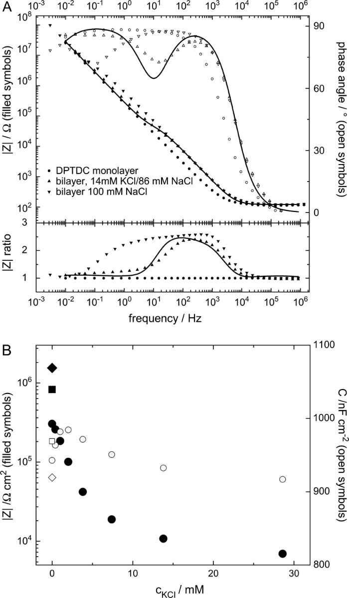
EIS of a bilayer and the effect of incorporated valinomycin at different K+/Na+ concentrations. A shows EIS data in a 100 mM NaCl buffer of a DPTDC covered substrate before vesicle fusion (circles), EIS in a 14 mM KCl/86 mM NaCl buffer after vesicle fusion and addition of 18 μM valinomycin in the cell (upward triangles), and EIS of the same bilayer after thorough rinsing with 100 mM NaCl (downward triangles). The line is a fit of an equivalent circuit (Fig. 3 B). To focus on their differences, the lower part of A displays the same impedance data but normalized to the EIS before vesicle fusion. It can be seen that in the frequency range where the valinomycin acts (below ∼10 Hz, upward triangles) the impedance of the bilayer is strongly reduced, albeit not all the way down to the impedance of the monolayer. In B, circles mark valinomycin incorporated bilayer resistances (•) and capacitance (○) from fits to EIS at different K+/Na+ ratios but constant 100 mM ion strength. After a rapid drop, the bilayer resistance approaches a constant value of ∼7 kΩ cm2 for higher KCl concentrations. The bilayer resistance in 100 mM NaCl before valinomycin incorporation (▪) is lower than after incorporation and rinsing with 100 mM NaCl (♦), which might be due to traces of K+ ions left in the valinomycin. Whereas the resistance varies over two orders of magnitude, the capacitance stays in a narrow range. A pure, protein-free bilayer did not show any or showed very little dependence on the various K+/Na+ ratios.
With increasing potassium concentration the resistance of the bilayer decreases as expected, first rapidly then slower until it approaches for higher potassium concentrations asymptotically a small fraction of the original bilayer resistance. At the same time, the membrane capacitance remains almost constant. After rinsing with 100 mM NaCl solution, the membrane resistance increases again.
As a control, electrolyte solutions with different NaCl/KCl concentrations at 100 mM ionic strength show no significant effect on the electrical properties of a protein-free bilayer.
As a second test on the functionality of the membrane, we incorporated gramicidin into the bilayer. Gramicidin is a polypeptide with alternating D and L amino acids. In lipid bilayer membranes, gramicidin dimerizes and folds as a right handed β-helix to form an ion channel that just spans the bilayer (30,31). Whereas K+ and Na+ ions penetrate the channel, other ions like the bigger tetramethylammonium ((CH3)4N+) or ammonium ( ) ions are excluded (32). This effect has already been proposed to be used in a biosensing concept (33–35). However, most of the approaches are based on black lipid membranes that lack mechanical stability. Supported systems, on the other hand, do not give highly insulating membranes. In our approach, we are now able to combine the stability of a tethered membrane with a highly insulating bilayer, which can be used for biosensing applications on semiconductor chips.
Fig. 6 A shows the Bode plot for a bilayer built on a DPTTC monolayer in 100 mM KCl before and after addition of gramicidin to the buffer and after rinsing with tetramethylammoniumchloride solution. The data are fitted using the same approach as above. The decrease of the bilayer resistance from 540 kΩ cm2 to 13 kΩ cm2 can be attributed to the incorporation of the gramicidin channels. This interpretation is affirmed by the strong increase of the bilayer resistance to 1.8 MkΩ cm2 after rinsing with tetramethylammoniumchloride solution. This resistance is even higher than the original bilayer resistance in KCl solution before gramicidin incorporation. This shows the influence of the different ion sizes and mobilities on the bilayer resistance. In control experiments, we find that membrane resistances in tetramethylammonium-chloride solution increase by a factor of ∼2 with respect to membranes in KCl solutions. The changes due to gramicidin incorporation are thus much more pronounced.
FIGURE 6.
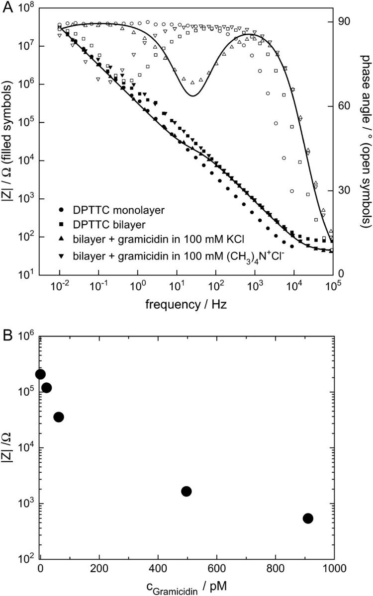
EIS of a tBLM and the effect of different ion size on the conductance of incorporated gramicidin channels. (A) EIS in a 100 mM KCl buffer of a DPTTC covered substrate before (circles) and after (squares) vesicle fusion, EIS in a 100 mM KCl/410 pM gramicidin buffer of the same bilayer (upward triangles) and EIS of the same bilayer after thorough rinsing with 100 mM tetramethylammoniumchloride (downward triangles). The data can be described using an equivalent circuit (Fig. 4 B). These fits yield in a bilayer resistance 540 kΩ cm2, a reduced bilayer resistance of 13 kΩ cm2 in the gramicidin buffer, and an increased bilayer resistance of 1.8 MΩ cm2 after rinsing with tetramethylammoniumchloride. Only one fit (line) is shown, for clarity reasons. (B) Resistances from a different experiment from fits to EIS in 100 mM KCl are plotted for different gramicidin concentrations. Whereas the bilayer resistance varies >2 orders of magnitude, the capacitance remains almost constant at ∼780 nF cm−2.
The obtained values for the bilayer resistance as a function of the gramicidin concentration are plotted in Fig. 6 B. A strong drop of the bilayer resistance by >2 orders of magnitude can be observed when the concentration of the ion channel is increased up to ∼1000 pM. At the same time, the bilayer capacitance is constant at 780 nFcm−2. For gramicidin concentrations below 500 pM, this drop in the bilayer resistance can be reversed by rinsing with a 100 mM (CH3)4N+Cl− buffer. For higher gramicidin concentrations, the bilayer resistance is reduced further until complete disappearance; also the initial bilayer resistance can no longer be regained by exchanging the buffer. This phenomenon could be due to permanent perturbation of the bilayer caused by a large amount of integrated protein molecules.
CONCLUSION
We have presented a tBLM architecture that is adapted to silicon oxide surfaces and shows high electrical sealing properties together with excellent mechanical and chemical stability. The two different anchor moieties monochloro- and trichlorosilane are able to graft the lipid molecules to a silicon oxide surface and enable the formation of a lightly packed hydrophobic monolayer. After vesicle fusion, both systems show bilayer resistances in the order of some MΩ cm2. These values are still lower than those of the similar thiol-based system (6,7), however high enough to study the functional incorporation of different membrane proteins.
Functionality of the membrane could be shown by the incorporation of two different membrane ionophores, the ion carrier valinomycin, and the ion channel gramicidin. We have shown the incorporation of valinomycin into a DPTDC and of gramicidin into a DPTTC system, respectively. One should notice that both systems could be functionalized with the respective other membrane transporter as well.
The coupling of artificial membrane systems to silicon oxide surfaces offers a way to combine the biological system of a membrane to the microelectronics world of silicon technology.
Acknowledgments
We thank Dr. J. Robertson for helpful discussion. Regina Stockmann and Dirk Borstlap are acknowledged for substrate preparation.
This study was supported by the Defense Advanced Research Projects Agency in the MOLDICE program. I.K. acknowledges support from the Laboratoire Européen Associé on “Polymers in Confined Geometries”.
References
- 1.Sackmann, E. 1996. Supported membranes: scientific and practical applications. Science. 271:43–48. [DOI] [PubMed] [Google Scholar]
- 2.Sackmann, E., and M. Tanaka. 2000. Supported membranes on soft polymer cushions: fabrication, characterization and applications. Trends Biotechnol. 18:58–64. [DOI] [PubMed] [Google Scholar]
- 3.Abdelghani, A., et al. 2001. Supported lipid membrane on semiconductor electrode. Mater. Chem. Phys. 70:187–190. [Google Scholar]
- 4.Krueger, S., et al. 2001. Investigation of hybrid bilayer membranes with neutron reflectometry: probing the interactions of melittin. Langmuir. 17:511–521. [Google Scholar]
- 5.Schuster, B., et al. 2001. S-layer ultrafiltration membranes: a new support for stabilizing functionalized lipid membranes. Langmuir. 17:499–503. [Google Scholar]
- 6.Naumann, R., et al. 2003. Tethered lipid bilayers on ultraflat gold surfaces. Langmuir. 19:5435–5443. [Google Scholar]
- 7.Schiller, S. M., et al. 2003. Archaea analogue thiolipids for tethered bilayer lipid membranes on ultrasmooth gold surfaces. Angew. Chem. 42:208–211. [DOI] [PubMed] [Google Scholar]
- 8.Braach-Maksvytis, V., and B. Raguse. 2000. Highly impermeable “soft” self-assembled monolayers. J. Am. Chem. Soc. 122:9544–9545. [Google Scholar]
- 9.Raguse, B., et al. 1998. Tethered lipid bilayer membranes: formation and ionic reservoir characterization. Langmuir. 14:648–659. [Google Scholar]
- 10.Naumann, R., et al. 2003. Kinetics of valinomycin-mediated K+ ion transport through tethered bilayer lipid membranes. J. Electroanal. Chem. 550–551:241–252. [Google Scholar]
- 11.Vitovic, P., S. Kresak, R. Naumann, S. M. Schiller, R. N. Lewis, R. N. McElhaney, and T. Hianik. 2004. The study of the interaction of a model alpha-helical peptide with lipid bilayers and monolayers. Bioelectrochemistry. 63:169–176. [DOI] [PubMed] [Google Scholar]
- 12.Naumann, R., T. Baumgart, P. Graber, A. Jonczyk, A. Offenhausser, and W. Knoll. 2002. Proton transport through a peptide-tethered bilayer lipid membrane by the H+-ATP synthase from chloroplasts measured by impedance spectroscopy. Biosens. Bioelectron. 17:25–34. [DOI] [PubMed] [Google Scholar]
- 13.Fromherz, P., et al. 1999. Membrane transistor with giant lipid vesicle touching a silicon chip. Applied Physics A. 69:571–576. [Google Scholar]
- 14.Purrucker, O., et al. 2001. Deposition of highly resistive lipid bilayer on silicon-silicon dioxide electrode and incorporation of gramicidin studied by AC impedance spectroscopy. Electrochim. Acta. 47:791–798. [Google Scholar]
- 15.Gervasi, C. A., and A. E. Vallejo. 2002. Sodium ion transport through gramicidin-doped bilayers. Influences of temperature and ionic concentration. Electrochim. Acta. 47:2259–2264. [Google Scholar]
- 16.Vallejo, A. E., and C. A. Gervasi. 2002. Impedance analysis of ion transport through gramicidin channels in supported lipid bilayers. Bioelectrochemistry. 57:1–7. [DOI] [PubMed] [Google Scholar]
- 17.Peggion, C., et al. 2001. A peptide-tethered lipid bilayer on mercury as a biomimetic system. Langmuir. 17:6585–6592. [Google Scholar]
- 18.Kim, J.-M., A. Patwardhan, A. Bott, and D. H. Thompson. 2003. Preparation and electrochemical behavior of gramicidin-bipolar lipid monolayer membranes supported on gold electrodes. Biochim. Biophys. Acta. 1617:10–21. [DOI] [PubMed] [Google Scholar]
- 19.Raguse, B., et al. 2000. The synthesis of archaebacterial lipid analogues. Tetrahedron Lett. 41:2971–2974. [Google Scholar]
- 20.Mathai, J. C., G. D. Sprott, and M. L. Zeidel. 2001. Molecular mechanisms of water and solute transport across archaebacterial lipid membranes. J. Biol. Chem. 276:27266–27271. [DOI] [PubMed] [Google Scholar]
- 21.Woese, C. R., and G. E. Fox. 1977. Phylogenetic structure of the prokaryotic domain: the primary kingdoms. Proc. Natl. Acad. Sci. USA. 74:5088–5090. [DOI] [PMC free article] [PubMed] [Google Scholar]
- 22.Lee, J. H., H. B. Lee, and J. D. Andrade. 1995. Blood compatibility of polyethylene oxide surfaces. Prog. Polym. Sci. 20:1043–1079. [Google Scholar]
- 23.Du, H., P. Chandaroy, and S. W. Hui. 1997. Grafted poly-(ethylene glycol) on lipid surfaces inhibits protein adsorption and cell adhesion. Biochim. Biophys. Acta. 1326:236–248. [DOI] [PubMed] [Google Scholar]
- 24.Prime, K. L., and G. M. Whitesides. 1991. Self-assembled organic monolayers: model systems for studying adsorption of proteins at surfaces. Science. 252:1164–1167. [DOI] [PubMed] [Google Scholar]
- 25.Arnold, K., O. Zschoernig, D. Barthel, and W. Herold. 1990. Exclusion of poly(ethylene glycol) from liposome surfaces. Biochim. Biophys. Acta. 1022:303–310. [DOI] [PubMed] [Google Scholar]
- 26.Ariga, K., J. S. Shin, and T. Kunitake. 1995. Interaction of lipid monolayers with aqueous neutral polymers and the consequent monolayer stabilization and improved Langmuir-Blodgett transfer. J. Colloid Interface Sci. 170:440–448. [Google Scholar]
- 27.Kallury, K. M. R., P. M. Macdonald, and M. Thompson. 1994. Effect of surface water and base catalysis on the silanization of silica by (aminopropyl)alkoxysilanes studied by x-ray photoelectron spectroscopy and 13C cross-polarization/magic angle spinning nuclear magnetic resonance. Langmuir. 10:492–499. [Google Scholar]
- 28.Tripp, C. P., and M. L. Hair. 1993. Chemical attachment of chlorsilanes to silica: a two-step amine-promoted reaction. J. Phys. Chem. 97:5693–5698. [Google Scholar]
- 29.Silberzan, P., et al. 1991. Silanation of silica surfaces. A new method of constructing pure or mixed monolayers. Langmuir. 7:1647–1651. [Google Scholar]
- 30.Langs, D. A. 1988. Three-dimensional structure at 0.86 Å of the uncomplexed form of the transmembrane ion channel peptide gramicidin A. Science. 241:188–191. [DOI] [PubMed] [Google Scholar]
- 31.Andersen, O. S., H. J. Apell, E. Bamberg, D. D. Busath, R. E. Koeppe 2nd, F. J. Sigworth, G. Szabo, D. W. Urry, and A. Woolley. 1999. Gramicidin channel controversy—the structure in a lipid environment. Nat. Struct. Biol. 6:609. [DOI] [PubMed] [Google Scholar]
- 32.Sancho, M. 1997. Electrostatic interactions and ion transport in narrow channels: the model system gramicidin. Solid State Ionics. 97:63–74. [Google Scholar]
- 33.Nikolelis, D., and C. Siontorou. 1996. Ammonium ion minisensors from self-assembled bilayer lipid membranes using gramicidin as an ionophore. modulation of ammonium selectivity by platelet-activating factor. Anal. Chem. 68:1735–1741. [DOI] [PubMed] [Google Scholar]
- 34.Cornell, B. A., V. L. Braach-Maksvytis, L. G. King, P. D. Osman, B. Raguse, L. Wieczorek, and R. J. Pace. 1997. A biosensor that uses ion-channel switches. Nature. 387:580–583. [DOI] [PubMed] [Google Scholar]
- 35.Hirano, A., M. Wakabayashi, Y. Matsuno, and M. Sugawara. 2003. A single-channel sensor based on gramicidin controlled by molecular recognition at bilayer lipid membranes containing receptor. Biosens. Bioelectron. 18:973–983. [DOI] [PubMed] [Google Scholar]
- 36.Schouten, P. G., J. F. VanderPol, J. W. Zwikker, W. Drenth, and S. J. Picken. 1991. Peripherally octasubstituted phtalocyanines with branched alkoxy chains. Mol. Cryst. Liq. Cryst. 195:291–305. [Google Scholar]
- 37.Ishiwatari, M., K. Yamada, and R. Ishiwatari. 2002. Pyrolytic formation of C19 isoprenoid hydrocarbons from dihydrophytol: in relation to the genesis of pristane in petroleum. Chem. Lett. 3:206–207. [Google Scholar]


