Abstract
In probing adhesion and cell mechanics by atomic force microscopy (AFM), the mechanical properties of the membrane have an important if neglected role. Here we theoretically model the contact of an AFM tip with a cell membrane, where direct motivation and data are derived from a prototypical ligand-receptor adhesion experiment. An AFM tip is functionalized with a prototypical ligand, SIRPα, and then used to probe its native receptor on red cells, CD47. The interactions prove specific and typical in force, and also show in detachment, a sawtooth-shaped disruption process that can extend over hundreds of nm. The theoretical model here that accounts for both membrane indentation as well as membrane extension in tip retraction incorporates membrane tension and elasticity as well as AFM tip geometry and stochastic disruption. Importantly, indentation depth proves initially proportional to membrane tension and does not follow the standard Hertz model. Computations of detachment confirm nonperiodic disruption with membrane extensions of hundreds of nm set by membrane tension. Membrane mechanical properties thus clearly influence AFM probing of cells, including single molecule adhesion experiments.
INTRODUCTION
Whether studying single cell adhesion by atomic force microscopy (AFM) or attempting to image or probe the mechanical properties of the cytoskeleton, contact always begins by indenting the cell's plasma membrane. Membrane mechanics has not yet been factored into AFM, even though membranes have long been known to be elastic in stretching and bending (1–3). In addition, the plasma membrane is also generally under a non-zero tension (4–6), which can influence physiological processes ranging from cell spreading to endocytosis (7,8). For deeply characterizing the mechanical properties and effects of cell membranes, an organelle-free cell such as the red cell is ideal, since it lacks complex structures and processes that modulate membrane tension. In addition, the red cell possesses a number of prototypical and important surface proteins, including CD47, which is examined here and implicated in adhesive signaling in the past (9).
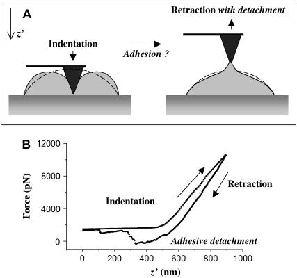
Although AFM has been widely used for cell imaging, it is also increasingly being used to probe a range of important adhesion receptors on various cells with ligand-functionalized AFM tips. These have recently included Notch/Delta interactions (10), which are key to signaling forces and dynamics in development, and P-selectin/PSGL-1 interactions (11), which are prominent in inflammation and blood-borne metastasis. The use of intact cells rather than purified proteins ensures proper ligand orientation, and preserves, among other physiological determinants, post-translational modifications. However, a commonly seen if unexplained feature in such AFM probing studies is the appearance of sawtooth patterns in detachment force (12,13). The patterns extend over several hundred nm of separation and are part of a bond's loading history, even if not taken into account in models applied thus far (11). Here, we attempt to incorporate membrane mechanical properties contributing to such sawtooth patterns by modeling AFM indentation-retraction during adhesion to the red cell membrane (Fig. 1 A).
FIGURE 1.
Regimes of AFM pulling of an adherent red cell. (A) AFM probing involves indentation and retraction. With a functionalized tip, adhesion is established with a counter-ligand so that, during retraction, adhesion bonds must be broken. (B) A typical force-curve for a pulling cycle is shown when a human RBC is probed with a SIRPα functionalized tip.
CD47 is the red cell receptor probed here. It is expressed on most cell types (14,15), and on mouse red cells it appears to bind macrophages and inhibit phagocytosis (16). In human red cells, CD47 is also linked to the cytoskeleton (9). CD47 binds SIRPα (17–19), and SIRPα has its own distribution from phagocytes (20,21) to stem cells (22,23). We exploit the representative interaction between CD47 on the red cell and SIRPα on an AFM tip to illustrate and then model specific nanoscale adhesion of an AFM tip with a cell.
A strongly adherent red cell emulates a spread cell with a well-defined membrane tension, T0 (24). This tension opposes cell deformation and limits the applicability of common force-indentation models (12,13) such as the Hertz model for a spherically tipped cantilever impinging on a homogeneous half-space and the Sneddon model for a conical tip. Although Daily et al. (25) worked out a membrane elastic model for cell-poking, their model neglected adhesion as well as a pre-tension and, since it predated AFM (26), it also did not consider sharpened probe tips. Recently, Pierrat et al. (27) studied forced detachment of red cells adhering to surfaces, where cell deformation profiles were used to relate unbinding forces and contact radii. Here we determine approximate expressions (24) for the membrane indentation force that accounts for T0 and the dilational modulus of the membrane, Ka, as well as the tip half-angle, θ, of the AFM's indenting tip. The general AFM indentation model for cell membranes that we develop is then used to simulate sawtooth profiles for detachment, as seen with membrane tethering by CD47-SIRPα interactions.
MATERIALS AND METHODS
Reagents
All reagents were from Sigma-Aldrich (St. Louis, MO): poly-L-lysine hydrobromide MW 2900, phosphate-buffered saline (PBS) tablets (0.01 M phosphate buffer/0.0027 M potassium chloride/0.137 M sodium chloride, pH 7.4), PKH67 dye, and bovine serum albumin (BSA). All solutions were made in filtered double-distilled water.
Production of recombinant human SIRPα1
COS-1 cells (ATCC, Manassas, VA) were transfected with pcDNA3-based vector (Invitrogen, Carlsbad, CA) encoding a human SIRPα1 extracellular domain fused to GST (Seiffert et al. (19)) using Lipofectamine 2000 (Invitrogen) per manufacturer's instructions. Secreted SIRPα1-GST (hereafter referred as SIRPα) was affinity-purified using Glutathione Sepharose 4B (Amersham Biosciences, Piscataway, NJ) as per manufacturer instructions and dialyzed against PBS (Invitrogen). The protein was stored at −20C after addition of 10% v/v glycerol (Fisher Scientific, Hampton, NJ).
Preparation of spread cells
One-hundred microliters of 10 mg/ml poly-L-lysine solution was allowed to adsorb for 10 min to a clean glass slide, and excess solution was drained away. The poly-L-lysine coated slide was allowed to dry under vacuum for at least 2 h. Fresh human blood was obtained from finger pricks of healthy donors. Rat blood was obtained from Covance (Princeton, NJ). Twenty microliters of fresh blood was washed three times in PBS containing 1% BSA at room temperature to get packed RBC. Packed human RBC was fluorescently labeled with PKH67, washed, and resuspended in PBS. For studying CD47-SIRP interactions, equal quantities of human and rat RBC mixed, and 100 μl of mixed RBC, were allowed to adhere to each poly-L-lysine coated glass slide for 10 min. Unattached cells were removed by gentle rinsing of the slide several times with PBS solution, and an additional volume of PBS was added for the experiments. For the other experiments, only human RBC was used.
AFM and preparation of functionalized tips
Force curves in vertical indentation and/or retraction of spread erythrocytes were obtained primarily with an Asylum Research AFM. This was mounted on the Nikon Eclipse TE 300 inverted microscope (Nikon, Tokyo, Japan).
For experiments aimed at studying adhesion mediated by CD47-SIRPα, blunt tips with nominal spring constants of 60 pN/nm (microlevers, Park Scientific, Sunnyvale, CA) were first silanized by immersion in a solution of 1.25% Allyltrichlorosilane in toluene. The silanized tips were then immersed in recombinant human SIRPα1-GST solution of desired concentration for 10 min. The functionalized tips were then washed thoroughly in 1% BSA (Sigma-Aldrich, St. Louis) solution in PBS to remove loosely attached protein. The retraction profiles seen in the adhesion experiments typically showed sawtooth patterns of force versus extension, with asymmetric peaks in force that were counted as peaks when the dropoff in force reached at least 50% toward the baseline. Small fluctuations in force on top of the basic sawtooth pattern were not further analyzed and are beyond the scope of this first analysis of the dominant process.
Sharpened cantilevers (microlevers, Park Cantilevers) were used for separate elasticity measurements of the indentation phase to minimize adhesion. Values for the cantilever spring constants were obtained by a manufacturer-supplied thermal noise method and were used in all calculations.
Membrane modeling
In all of the calculations that follow, the undeformed shape of the membrane is known a priori, since the initial shape is a sector of a sphere (24). When indented with an AFM tip, the supported portion of the membrane (segment in contact with the tip) conforms to the tip. For the unsupported portion, the mean curvature remains constant. This reduces to a differential equation, whose solution gives the contour of the surface as a function of the contact radius and the base angle (which are unknowns). The unknowns are determined from both the specified force and the constraint that the cell has constant volume. All of the derivations are detailed in Appendix 1. For the retraction part, we proceed in a similar manner to calculate the profile, but a given contact radius is assumed. In this case, we also solve for two unknowns—one being the base angle and the other being the angle made by the normal at the point in the membrane where it detaches from the tip.
RESULTS
Prototype adhesion
Any AFM pulling cycle starts with membrane indentation before retraction. Any adhesive bonds that form during indentation will tend to break during tip retraction—as manifested in the form of single or multipeak sawtooth patterns. Fig. 1 B illustrates a typical retraction curve obtained when a human red cell is probed with a tip functionalized with recombinant human-SIRPα. The retraction profile clearly reveals two peaks, representative of the formation of adhesive interactions.
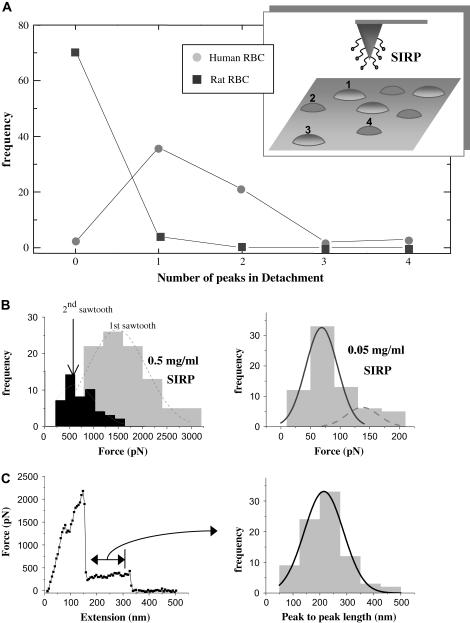
Specificity of this CD47-SIRPα interaction is readily established here by alternately probing human red cells and rat red cells with an AFM tip coated with human SIRPα. Since rat red cells clearly show no binding (Fig. 2 A) but otherwise have similar mechanical properties, the comparison is an important negative control to distinguish nonspecific adhesion. In contrast, almost all indentations of human RBC show at least one peak, with peak detachment forces increasing with SIRPα concentrations on the tip (Fig. 2 B), which proves consistent with a specific interaction.
FIGURE 2.
Probing CD47- SIRPα interactions. (A) CD47-SIRPα interaction is species-specific. Human RBC and rat RBC are alternately tapped with the human-SIRPα functionalized tip, showing significant interactions (one retraction peak or more) only with human RBC. (B) At a SIRPα concentration of 0.5 mg/ml, first peak forces are ∼1500 pN and second peak forces ∼600 pN, suggesting multiple bonds. However, unbinding forces decrease to ∼100 pN at 10-fold lower SIRPα. (C) A representative force-extension curve and the distribution of peak-to-peak length, which can be fitted by a Gaussian with a mean extension length of ∼215 nm.
At high SIRPα concentrations, first and second-peak force distributions, respectively, give Gaussian means of ∼1500 pN for the first peak and ∼600 pN for the second, final detachment peak. At the lower SIRPα concentration, 80% of retractions exhibit only a single peak, and the resulting force distribution fits very well to two Gaussians, with the first, dominant Gaussian averaging 70 pN. Although the latter fits typical ligand-receptor forces of ∼100 pN or less, the much higher forces for high ligand concentrations suggest multiple CD47-SIRPα interactions in parallel, even for the last detachment peak. This is relevant to receptor clusters hypothesized for this system. Though we have not addressed the effects of tip retraction rates on the magnitudes of unbinding forces and one might expect a nonlinear dependence as observed in other systems (28–30), the response may be further complicated by membrane tension and elasticity. Indeed, although the forces of interaction for this experimental system are certainly biologically relevant, the results are presented here primarily as illustrative for modeling of AFM-membrane mechanics.
Asymmetric sawtooths seen in retraction partially motivate the modeling, in that they yield a distribution of peak-to-peak lengths that average ∼215 nm, which is relatively large. Both CD47 and SIRPα are Immunoglobulin-type cell adhesion molecules (CAMs) and should unfold under forces <100 pN (31,32); but peak-to-peak lengths for unfolding such CAMs are much <50 nm. Protein unfolding cannot therefore contribute significantly to the observed extensions, suggesting that membrane properties determine such long extensions. Additionally, linkage of CD47 to the spectrin skeleton (9) is likely to have a major role in limiting the extensions here, since lipid membrane tethers many microns in length have been documented to occur at forces of ∼50 pN in red cells (33). It could be interesting in further work to sever the CD47-spectrin linkage (mediated by protein 4.2; (34)) with the expectation of longer, lipid-based tethers being formed.
Motivated by the prototypical adhesion results above, a model is elaborated below for the force profile during membrane indentation and retraction. We explicitly account for cell and tip geometries, tension in the membrane, and the area elasticity of the membrane. We eventually use the experimental distributions of detachment forces as inputs and vary the membrane tension to compute peak-to-peak lengths and membrane contours during simulated sawtooths.
Indentation model
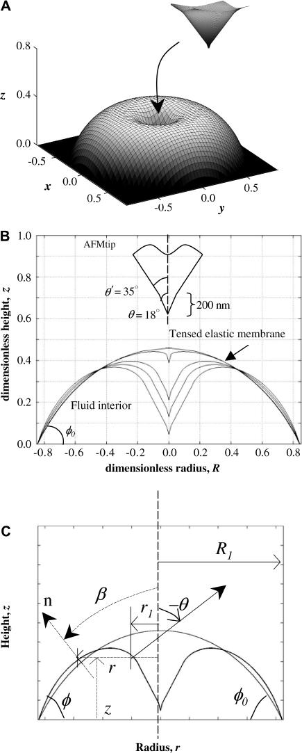
Strong adhesion of red cells to poly-L-lysine coated coverslips leads to spherically capped shapes for the cells (Fig. 3), with substrate contact angles of φ0 ∼ 60° (24). In the model that follows, the red cell membrane is considered elastic and isotropic in its plane. The effects of bending are neglected to first approximation, and the dominant resistance to indentation is taken as the isotropic tension. Another assumption is that the AFM tip indents the cell along the vertical center-line, providing axisymmetry both in geometry and loading. Fig. 3 illustrates the contours of such a red cell when progressively indented with a conical AFM tip (tip geometry inset in Fig. 3 B); the initial contour is a section of a sphere of radius Rs = 1. Throughout the indentation, the membrane is assumed to be under an isotropic tension, and the adhesive contact area is unchanged. A representative three-dimensional shape is shown in Fig. 3 A, with the deformed central portion contacting the tip shown as an inset. The deformation conforms increasingly to the tip as it indents (Fig. 3 B). Since the tip geometry clearly stays constant and bending resistance would dominate in the initial nm's of indentation, the subsequent resistance offered by the membrane through much of the indentation beyond ∼10 nm is due to the isotropic tension.
FIGURE 3.
Adherent red cell indented under an AFM tip. (A) Axisymmetric shape when isotropic tension and elastic stretching of the membrane oppose indentation. (B) Cross-sections of the membrane as it is increasingly deformed under a sharpened AFM tip. The initial shape is a spherical cap of unit radius R0. Cell volume is constant, and strong adhesion keeps the base radius fixed at R1 = R0 sin φ0. (C) For one typical deformed configuration, the parameters used in Appendix 1 are shown.
Force curves at small indentations
The strong adhesion between the cells and poly-L-lysine generates a pre-stress, T0, in the membrane. On long timescales (∼1 h), tension is not sustainable and T0 leads to membrane rupture. During indentation of the intact cell, the tension increases in proportion to the area dilation, α. The membrane tension is thus a sum of dilation (Kaα, where Ka is the dilation modulus) and pre-stress and is given by
 |
(1) |
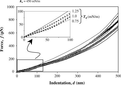
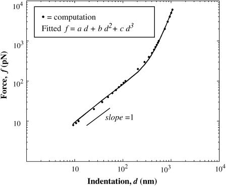
Fig. 4 overlays experimentally obtained force curves with calculated force curves. An adhesion-induced initial tension T0 in the range of 0.75–1.25 mN/m fits very well with determinations from past experiments (24). The model's Ka ≈ 450 mN/m also compares very well with determinations made by micropipette aspiration (1,35). For the first 100–200 nm of indentation here, the force curves are essentially linear with the constant pre-stress being the dominant component as elaborated below. With further indentation, Ka becomes increasingly important, as force increases dramatically and becomes increasingly nonlinear.
FIGURE 4.
Force-indentation curves for indentation ≤500 nm. Force-indentation curves that compare experimental datapoints to computed profiles. For the first 100 nm, the force curves are almost linear (inset).
Analysis of nonlinear indentation curves
The force curves should, it seems, depend separately on both the elasticity of the membrane and the geometry of the tip. Fig. 5 shows a calculated force curve for T0 = 1 mN/m and Ka = 450 mN/m (tip geometry shown in Fig. 3); also shown is a weighted fit of the curve using a cubic polynomial. The fit matches the computed force curve very closely, and thus the observation of linearity above appears correct. The polynomial coefficients are functions of T0, Ka, and tip geometry, with details provided in Appendix 2.
FIGURE 5.
Computed force curve for T0 = 1 mN/m, Ka = 450 mN/m for a sharp tip. Fitted R2 = 0.99.
In fitting, the computed force-indentation curves are written as
 |
(2) |
The linear coefficient, a, is shown to be dominated by T0 whereas the cubic coefficient, c, is dominated by Ka over the relevant parameter ranges. Comparing with previous theories of indentation—notably Sneddon's theory for a cone that gives f ∼ d2—the polynomial fits here show that simple scaling laws for forced indentation of a membrane are inadequate. Hategan et al. (24) obtained an analytical expression for the initial force-indentation behavior; the equation contains both linear and cubic terms in d (i.e., b = 0). The linear d-term contained T0 but not Ka, whereas the d3-term contained Ka but not T0.
Hategan et al. (24) also included factors for tip geometry in their polynomial expression. To leading order, sin θ appeared in both terms. The obtained curves are fit well by polynomial functions of the form g1 θ + g3 θ3 + g5 θ5, resembling a Taylor series expansion of sin θ. Indeed, for θ < 20°, the coefficients can be approximated fairly well by g sin θ. The results thus confirm that the force-indentation curves depend on a simple feature of tip geometry consistent with Hategan et al. (24).
Prediction of cell lysis
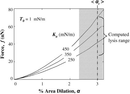
Constrained by cell volume, strong adhesion tenses the membrane initially, but AFM indentation increasingly stretches the membrane. Fig. 6 shows computed force curves at large indentations with a sharpened tip, and for T0 = 1.0 mN/m and Ka varying from 250 to 450 mN/m. Evans et al. (1) showed that lysis of red cell membranes occurs at an average critical dilation of αc ∼ 3 ± 0.7%, under lysis tensions of 10–12 mN/m in micropipette aspiration. Based on these limits, the computations here predict lysis forces as low as 25 nN, which is in reasonable agreement with Hategan et al. (24), who presented data for lysis under pyramidal tips in the force range of 14–27 nN.
FIGURE 6.
Force versus membrane dilation for various Ka and fixed T0. Lysis occurs in quasistatic micropipette aspiration at 3 ± 0.7% membrane dilation (shaded region) (Waugh and Evans (3)).
Model-simulated sawtooth patterns
To better understand the mechanics of the sawtooth detachment profiles, we used the parameters above for sublytic indentation and simulated adhesive retraction by AFM to determine the geometry of the cell as the tip retracts and breaks adhesive bonds. By comparing simulations and experiments, the key role of membrane tension on the distribution of peak-to-peak lengths becomes clear. For all calculations here, a blunt tip is assumed (35° half-angle, which is similar to tips used in experiments). Based on symmetry in geometry and loading, the asymmetric sawtooths, and sharp drops in the sawtooths from the peak forces to the baseline, we assume that during indentation distinct adhesive zones or rings are formed—the appearance of more than one detachment peak and instantaneous detachment eliminate the possibility of continuous peeling. For these simple simulations, we specify a representative detachment force that depends on the number of bonds needed to break an adhesive ring per experimental results (Fig. 2 B). The contact radius represents the size of the ring, and the number of adhesive rings and their sizes depend on the depth of indentation, with larger indentations giving rings that are more adhesive as well as rings of larger size. When an adhesive ring is intact and mediating attachment, the force exerted by the tip is directly transmitted to the membrane, which extends until the adhesive ring is disrupted. Contact then shifts to the next adhesive ring at a smaller radius—and, as shown in Fig. 2 B, a smaller force is required to break the subsequent adhesive ring. The process continues until all of the adhesive rings are broken.
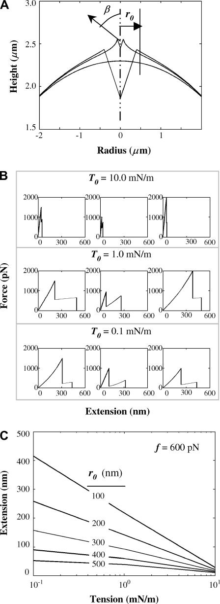
To illustrate the interplay between adhesion and contact radius on membrane deformation and extension, Fig. 7 A shows two cusped membrane profiles corresponding to contact radii of 400 nm (detachment at 1500 pN) and 75 nm (detachment at 600 pN). Membrane profiles thus show that extension—as defined by maximum height above the undeformed contour—increases nonlinearly as the contact radius is reduced.
FIGURE 7.
Generating sawtooths under AFM retraction. (A) Two cusped membrane profiles are shown for a contact radius of 400 nm (detachment force of 1500 pN) and contact radius of 75 nm (detachment force of 600 pN). (B) A series of simulated sawtooths are shown for different T0 varying over three orders of magnitude. With increasing T0, peak-to-peak length decreases drastically. (C) For varying r0, extension is plotted as a function of tension keeping detachment force constant at 600 pN. Increasing contact radius or increasing tension reduces extension.
To assess the effect of membrane tension on peak-to-peak length, a series of sawtooth patterns are plotted in Fig. 7 B. The tension T0 is varied over three decades from 0.1 mN/m to 10 mN/m. For each tension, three sawtooth profiles are plotted. The magnitudes of the forces and the contact radii are chosen to be almost the same. For T0 = 1 mN/m, the peak-to-peak lengths lie in the range of 100–300 nm, which closely matches the distribution obtained in our adhesion studies. For T0 = 10 mN/m the peak-to-peak lengths are in tens of nm. This shows that membrane tension plays an essential role in setting the peak-to-peak lengths.
In Fig. 7 C, extension is plotted as a function of T0 for different contact radii and a constant detachment force of 600 pN. For the same contact radii and the same force, a decreasing tension leads to increased extension albeit in a nonlinear manner. Also, for the same tension, a smaller radius gives a higher extension. Thus, for small tensions and small contacts, one can obtain ½-μm extensions that are suggestive of nascent membrane tethers (5). However, due to the cytoskeletal constraints imposed on CD47, lipid tethers are unlikely to be drawn out in this system.
DISCUSSION
Using intact human red cells, we demonstrate a prototypical but clearly specific interaction between human CD47 and human SIRPα. Specificity is clear in the finding that human SIRPα does not interact with rat red cells. By reducing the tip density of SIRPα to a minimum, we determine single molecule interactions with CD47, and determine that 70 pN is the force required to break a single CD47-SIRPα bond when stressed at displacements of 5–10 μm/s. At higher SIRPα concentrations, where high-force multipeak sawtooths are seen, peak-to-peak lengths >200 nm suggest a role for membrane elasticity, as opposed to, for example, protein unfolding. To understand the role of membrane tension in such force and length scales, we first analyzed the indentation profiles under a sharpened AFM tip.
From the indentation profiles, membrane elasticity is shown to be critical at moderate forces and up to rupture (<5–10 nN). In the classical elastic model of cell membranes, the membrane's response to a given stress is assumed to be linear in a suitable strain measure. Three elastic moduli have proven important: the area expansion modulus Ka that reflects the strong resistance to dilation of lipid bilayers, the shear modulus μ attributable to an underlying membrane network, and the bending stiffness Kb which is related to Ka through lipid membrane thickness (squared). For the red cell, the bending stiffness is estimated to be small (36,37), and is generally too small to have a noticeable influence on the membrane response in all but the most highly curved or unstressed regions. Bending seems more important with membrane tethers (38,39), spicules (40), and thermal undulation (41). The shear modulus μ is estimated to be in the range of 4–10 mN/m and matters little when isotropic tensions are high as here. In such a case as this, membrane tension and Ka dominate, and the latter is expected to lay in the range 240–500 mN/m (1, 35). The results presented here prove consistent with these determinations.
The approach here provides a model study in cell membrane indentation. The governing equations (involving the initial geometry and the applied forces) were obtained and shown to be numerically solvable for the deformed shapes as well as the force-indentation curves. Comparing to experimental f versus d curves leads to estimates of T0 in the range of 0.75–1.25 mN/m and a dilation modulus of ∼450 mN/m, which are in reasonably good agreement with past determinations. From the three-dimensional shapes (Fig. 3 A), it also becomes clear that indentation with AFM tips is largely localized, with isotropic tension distributing the load radially.
The force curves appear to be polynomials in indentation d, with coefficients depending on membrane elasticity and tip geometry. In systematically elucidating the effects of T0, Ka, and tip geometry in the deformation of strongly adherent red cells, the nature of membrane deformation is clarified. Clearly inadequate are the common scaling laws such as the Hertz model f = E/(1 − ν2) (4/3 (Rindenter)1/2) d3/2 for indentation with a spherical tip, or the Sneddon model f = E/(1 − ν2) 2/π tan θ d2 for indentation with a conical tip. A better approximation by Hategan et al. (24) f = ½ T0 sin η ζtip d + ½ Ka /A0 sin η ( )d 3 was based on a simple tip geometry factor ζtip and a wetting angle η specific to loading under a tip.
Differences in lysis force between experiment and theory here are not surprising since lysis is complicated by a number of factors beyond the elasticity of the membrane. Evans and Ludwig (42) have shown that lysis depends on the timescale of stress application, as confirmed by Hategan et al. (24) for the red cell.
From our simulated sawtooths, we elucidate the role of membrane tension and elasticity on setting the magnitudes of detachment forces and peak-to-peak lengths. Asymmetric sawtooths suggest the formation of critical rings of attachment—analogous to instabilities in droplet formation, etc. By simply simulating detachment of these rings through specification of the unbinding forces to be the same as those obtained experimentally, we show that it is possible to obtain 200-nm peak-to-peak lengths. Though we have not addressed the role of tip velocity on unbinding forces, work done by others (28–30) on different biological systems certainly suggests that unbinding forces increase nonlinearly with loading rates.
Of future interest is whether the force curves are universal across cell types and for a range of loading patterns. Improvements to the model can be made if bending is added and symmetry conditions lifted. Also for studying protein unfolding from intact cell surfaces, membranes, or other soft surfaces, the signatures of asymmetric sawtooth profiles have to be better understood to differentiate protein unfolding from membrane extension. Nonetheless, the model computations here can be used to gain valuable insights into adhesive tension, membrane elastic properties, and the effects of these on force and length scales.
APPENDIX 1
Indentation of red cell with AFM tip
Fig. 3 C shows undeformed and deformed configurations of the red cell. A net force of magnitude f is applied with a conical tip to indent the membrane axisymmetrically. This is done in such a manner that the volume enclosed within the membrane is always constant.
Depending on the force applied, there will be a considerable region of contact between the cell and the tip. Let r1 be the radial position beyond which the membrane is freely supported (i.e., it is not in contact with the tip), and, R1 be the base radius, which is fixed. The values θ and φ are the angles that the normals at r1 and R1 make with the vertical. At any point on the surface, the radius is r and the height is z. The values r1and φ are unknowns to be determined.
For developing the underlying theory, let us introduce the following terms:
T is the isotropic tension in the membrane which is uniform throughout the membrane,
ΔP denotes the hydrostatic pressure difference which is constant, and
Rm and Rφ denote the meridional and circumferential radius of curvature at any point in the membrane.
From static equilibrium, we can derive the equation between T and ΔP by the relation
 |
(A1) |
Since the tension in the membrane is constant and so is the hydrostatic pressure difference, we conclude that
 |
(A2) |
By using differential geometry, we can rewrite Eq. 2 as
 |
(A3) |
where u = sin β, where β is the angle at which the normal at any point on the surface meets the vertical axis. For solving Eq. A3, we need two boundary conditions, which are
 |
(A4) |
By applying these two boundary conditions, we can write u as a function of r as u = Ar + B/r, where A and B are given by the expressions
 |
(A5) |
It is to be noted that all these quantities are functions of r1 and φ, which are to be determined from two equations. One of these equations is that the interior of the membrane is incompressible—thus the volume remains constant. From the initial radius of the sphere, the initial volume V0 can be easily determined. The volume of the deformed membrane can be calculated from
 |
(A6) |
and set to V = V0. For a section through the cell parallel to surface, the force balance can be written down and rearranged to
 |
(A7) |
The left side of this expression represents a dimensionless force and is only a function of r1 and φ. If the isotropic membrane tension is constant, then we can use Eq. A7 directly.
If T = Kaα, where α represents the area dilation, then Eq. A7 can be rewritten as
 |
(A8) |
If T = T0 + Kaα, then we can write
 |
(A9) |
Note that the dilation α is given by α = (Asurf − A0)/A0, where the surface area Asurf is calculated using the expression
 |
(A10) |
Thus, we have two nonlinear equations in two unknowns, and these can be solved given a value of the force. By defining the unknown vector z = [r1 φ]T, we solve the equation F(z) = [0 0]T, where F(z) is given by Eq. A6 and one of Eqs. A7–A9. The two nonlinear equations are solved using the built-in MatLab function fsolve (The MathWorks, Natick, MA). Once r1 and φ are solved for, the deformed shape of the membrane can be computed by integrating the equation dz = dr tan β. Thus the z-position corresponding to any radius can be computed from the expression
 |
(A11) |
Retraction of red cell with AFM tip
Fig. 7 A shows the deformed configurations of the red cell when the AFM tip is retracting. During the indentation there can be one or multiple adhesive bands formed between the tip and the membrane. A net force of magnitude f has to be applied by the tip to rupture an adhesive strip of contact radius r0. The unknowns at any instant are the base angle φ, and the angle β, formed by the normal at the point in the membrane where it detaches from the tip, and the axis of symmetry. The expressions for A and B are
 |
(A12) |
The force equation during retraction is given by
 |
(A13) |
APPENDIX 2
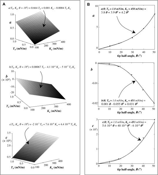
Varying T0 from 0.01 to 1 mN/m, and Ka from 100 to 400 mN/m, while keeping the half-angle fixed at 18° (the sharp tip has a half-angle of 18°), a wide range of force curves are calculated and then fit with cubic polynomials. Appendix Fig. 1 A shows a plot of each of the coefficients of the cubic polynomials over the range of T0 and Ka. From these plots, each of these coefficients can be expressed as a function of T0 and Ka. Appendix Fig. 1 B shows the variation of the coefficients (of the polynomial fit) with the tip half-angle, for fixed T0 = 1.0 mN/m and Ka = 450 mN/m. Thus a = a(T0, Ka, θ), b = b(T0, Ka, θ), and c = c(T0, Ka, θ). The effects of tip geometry and membrane elasticity appear relatively independent in the relevant range. Algebraically, it can be shown that a = a1(T0, Ka) a2(θ)/[a1(T0 = 1.0, Ka = 450) a2(θ = 18°)]½, where a1(T0, Ka) is obtained from Appendix Fig. 1 A and a2(θ) is obtained from Appendix Fig. 1 B. Similarly, b and c are determined. The final expressions for the coefficients are
 |
 |
 |
(A14) |
APPENDIX FIGURE 1.
Coefficient variations for polynomial fits of indentation over physically reasonable ranges of T0 and Ka. (A) The cone angle is fixed at θ = 18°. The coefficient a in Eq. 2 is generally dominated by T0 and the cubic term c is dominated by Ka. Fitted expressions are shown above each surface. (B) Dependence of each of the coefficients of the force-indentation polynomial fit (Eq. 2) on the tip angle, with fixed T0 = 1.0 mN/m, Ka = 450 mN/m. The big dots denote the points obtained from computation and are fitted by polynomials of the form g1 θ + g3 θ3 + g5 θ5. The curves are almost linear for tip angles <20°, and can be approximated by g sin θ shown by the dotted line.
Polynomials with higher-order terms in T0, Ka, and θ seem likely at higher forces.
Acknowledgments
The expression vector used for the preparation of human SIRPα was a kind gift from Dr. Axel Ullrich (Max-Planck-Institute for Biochemistry, Germany).
Support for this work was provided by a National Institutes of Health R01 grant to D.E.D.
References
- 1.Evans, E. A., R. Waugh, and L. Melnik. 1976. Elastic area compressibility modulus of red cell membrane. Biophys. J. 16:585–595. [DOI] [PMC free article] [PubMed] [Google Scholar]
- 2.Lipowsky, R., and E. Sackmann. 1995. The Structure and Dynamics of Membranes. Elsevier, Dordrecht, The Netherlands.
- 3.Waugh, R., and E. A. Evans. 1976. Viscoelastic properties of erythrocyte membranes of different vertebrate animals. Microvasc. Res. 12:291–304. [DOI] [PubMed] [Google Scholar]
- 4.Dai, J., M. P. Sheetz, X. Wan, and C. E. Morris. 1998. Membrane tension in swelling and shrinking molluscan neurons. J. Neurosci. 18:6681–6692. [DOI] [PMC free article] [PubMed] [Google Scholar]
- 5.Hochmuth, R. M., and W. D. Marcus. 2002. Membrane tethers formed from blood cells with available area and determination of their adhesion energy. Biophys. J. 82:2964–2969. [DOI] [PMC free article] [PubMed] [Google Scholar]
- 6.Raucher, D., and M. P. Sheetz. 1999. Characteristics of a membrane reservoir buffering membrane tension. Biophys. J. 77:1992–2002. [DOI] [PMC free article] [PubMed] [Google Scholar]
- 7.Hategan, A., K. Sengupta, S. Kahn, E. Sackmann, and D. E. Discher. 2004. Topographical pattern dynamics in passive adhesion of cell membranes. Biophys. J. 87:3547–3560. [DOI] [PMC free article] [PubMed] [Google Scholar]
- 8.Raucher, D., and M. P. Sheetz. 2000. Cell spreading and lamellipodial extension rate is regulated by membrane tension. J. Cell Biol. 148:127–136. [DOI] [PMC free article] [PubMed] [Google Scholar]
- 9.Dahl, K. N., C. M. Westhoff, and D. E. Discher. 2003. Fractional attachment of CD47 (IAP) to the erythrocyte cytoskeleton and visual colocalization with Rh protein complexes. Blood. 101:1194–1199. [DOI] [PubMed] [Google Scholar]
- 10.Ahimou, F., L. P. Mok, B. Bardot, and C. Wesley. 2004. The adhesion force of Notch with Delta and the rate of Notch signaling. J. Cell Biol. 167:1217–1229. [DOI] [PMC free article] [PubMed] [Google Scholar]
- 11.Hanley, W., O. McCarty, S. Jadhav, Y. Tseng, D. Wirtz, and K. Konstantopoulos. 2003. Single molecule characterization of P-selectin/ligand binding. J. Biol. Chem. 278:10556–10561. [DOI] [PubMed] [Google Scholar]
- 12.Grandbois, M., W. Dettmann, M. Benoit, and H. E. Gaub. 2000. Affinity imaging of red blood cells using an atomic force microscope. J. Histochem. Cytochem. 48:719–724. [DOI] [PubMed] [Google Scholar]
- 13.Wojcikiewicz, E. P., X. Zhang, A. Chen, and V. T. Moy. 2003. Contributions of molecular binding events and cellular compliance to the modulation of leukocyte adhesion. J. Cell Sci. 116:2531–2539. [DOI] [PMC free article] [PubMed] [Google Scholar]
- 14.Lindberg, F. P., D. C. Bullard, T. E. Caver, H. D. Gresham, A. L. Beaudet, and E. J. Brown. 1996. Decreased resistance to bacterial infection and granulocyte defects in IAP-deficient mice. Science. 274:795–798. [DOI] [PubMed] [Google Scholar]
- 15.Campbell, I. G., P. S. Freemont, W. Foulkes, and J. Trowsdale. 1992. An ovarian tumor marker with homology to Vaccinia virus contains an IgV-like region and multiple transmembrane domains. Cancer Res. 52:5416–5420. [PubMed] [Google Scholar]
- 16.Oldenborg, P. A., A. Zheleznyak, Y. F. Fang, C. F. Lagenaur, H. D. Gresham, and F. P. Lindberg. 2000. Role of CD47 as a marker of self on red blood cells. Science. 288:2051–2054. [DOI] [PubMed] [Google Scholar]
- 17.Babic, I., A. Schallhorn, F. P. Lindberg, and F. R. Jirik. 2000. SHPS-1 induces aggregation of Ba/F3 Pro-B cells via an interaction with CD47. J. Immunol. 164:3652–3658. [DOI] [PubMed] [Google Scholar]
- 18.Jiang, P., C. F. Lagenaur, and V. Narayanan. 1999. Integrin-associated protein is a ligand for the P84 neural adhesion molecule. J. Biol. Chem. 274:559–562. [DOI] [PubMed] [Google Scholar]
- 19.Seiffert, M., C. Cant, Z. Chen, I. Rappold, W. Brugger, L. Kanz, E. J. Brown, A. Ullrich, and H. J. Buhring. 1999. Human signal-regulatory protein is expressed on normal, but not on subsets of Leukemic myeloid cells and mediates cellular adhesion involving its counterreceptor CD47. Blood. 94:3633–3643. [PubMed] [Google Scholar]
- 20.de Vries, H. E., J. J. A. Hendriks, H. Honing, C. R. de Lavalette, S. M. A. van der Pol, E. Hooijberg, C. D. Dijkstra, and T. K. van den Berg. 2002. Signal-regulatory protein α-CD47 interactions are required for the transmigration of monocytes across cerebral endothelium. J. Immunol. 168:5832–5839. [DOI] [PubMed] [Google Scholar]
- 21.Liu, Y., H. J. Buhring, K. Zen, S. L. Burst, F. J. Schnell, I. R. Williams, and C. A. Parkos. 2002. Signal regulatory protein (SIRPα), a cellular ligand for CD47. Regulates neutrophil transmigration. J. Biol. Chem. 277:10028–10036. [DOI] [PubMed] [Google Scholar]
- 22.Giesert, C., G. Almeida-Porada, A. Scheffold, L. Kanz, E. D. Zanjani, and H. J. Buhring. 2001. The monoclonal antibody W7C5 defines a novel surface antigen on hematopoietic stem cells. Ann. N. Y. Acad. Sci. 938:175–183. [DOI] [PubMed] [Google Scholar]
- 23.Oh, E. S., H. Gu, T. M. Saxton, J. F. Timms, S. Hausdorff, E. U. Frevert, B. B. Kahn, T. Pawson, B. G. Neel, and S. M. Thomas. 1999. Regulation of early events in integrin signaling by protein tyrosine phosphatase SHP-2. Mol. Cell. Biol. 19:3205–3215. [DOI] [PMC free article] [PubMed] [Google Scholar]
- 24.Hategan, A., R. Law, S. Kahn, and D. E. Discher. 2003. Adhesively-tensed cell membranes: lysis kinetics and atomic force microscopy probing. Biophys. J. 85:2746–2759. [DOI] [PMC free article] [PubMed] [Google Scholar]
- 25.Daily, B., E. L. Elson, and G. I. Zahalak. 1984. Cell poking. Determination of the elastic area compressibility modulus of the erythrocyte membrane. Biophys. J. 45:671–682. [DOI] [PMC free article] [PubMed] [Google Scholar]
- 26.Binning, G., C. F. Quate, and C. Gerber. 1985. Atomic force microscopy. Phys. Rev. Lett. 56:930–933. [DOI] [PubMed] [Google Scholar]
- 27.Pierrat, S., F. Brochard-Wyart, and P. Nassoy. 2004. Enforced detachment of red blood cells adhering to surfaces: statics and dynamics. Biophys. J. 87:2855–2869. [DOI] [PMC free article] [PubMed] [Google Scholar]
- 28.Berquand, A., N. Xia, D. G. Castner, B. H. Clare, N. L. Abbott, V. Dupres, Y. Adriaense, and Y. F. Dufrene. 2005. Antigen binding forces of single antilysozyme fv fragments explored by atomic force microscopy. Langmuir. 21:5517–5523. [DOI] [PubMed] [Google Scholar]
- 29.Evans, E., V. Heinrich, A. Leung, and K. Kinoshita. 2005. Nano- to microscale dynamics of P-selectin detachment from leukocyte interfaces. I. Membrane separation from the cytoskeleton. Biophys. J. 88:2288–2298. [DOI] [PMC free article] [PubMed] [Google Scholar]
- 30.Hanley, W. D., D. Wirtz, and K. Konstantopoulos. 2004. Distinct kinetic and mechanical properties govern selectin-leukocyte interactions. J. Cell Sci. 117:2503–2511. [DOI] [PubMed] [Google Scholar]
- 31.Carl, P., C. H. Kwok, G. Manderson, D. W. Speicher, and D. E. Discher. 2001. Forced unfolding modulated by disulfide bonds in the Ig domains of a cell adhesion molecule. Proc. Natl. Acad. Sci. USA. 98:1565–1570. [DOI] [PMC free article] [PubMed] [Google Scholar]
- 32.Bhasin, N., P. Carl, S. Harper, G. Feng, H. Lu, D. W. Speicher, and D. E. Discher. 2004. Chemistry on a single protein, vascular cell adhesion molecule-1, during forced unfolding. J. Biol. Chem. 279:45865–45874. [DOI] [PubMed] [Google Scholar]
- 33.Waugh, R. E., and R. G. Bauserman. 1995. Physical measurements of bilayer-skeletal separation forces. Ann. Biomed. Eng. 23:308–321. [DOI] [PubMed] [Google Scholar]
- 34.Dahl, K. N., R. Parthasarathy, C. M. Westhoff, D. M. Layton, and D. E. Discher. 2004. Protein 4.2 is critical to CD47-membrane skeleton attachment in human red cells. Blood. 103:1131–1136. [DOI] [PubMed] [Google Scholar]
- 35.Katnik, C., and R. Waugh. 1990. Electric fields induce reversible changes in the surface to volume ratio of micropipette-aspirated erythrocytes. Biophys. J. 57:865–875. [DOI] [PMC free article] [PubMed] [Google Scholar]
- 36.Evans, E. A. 1983. Bending elastic modulus of red blood cell membrane derived from buckling instability in micropipette aspiration tests. Biophys. J. 43:27–30. [DOI] [PMC free article] [PubMed] [Google Scholar]
- 37.Peterson, M. A., H. Strey, and E. Sackmann. 1992. Theoretical and phase contrast microscopic eigenmode analysis of erythrocyte flicker: amplitudes. J. Phys. II (Fr.). 2:1273–1285. [Google Scholar]
- 38.Bozic, B., S. Svetina, and B. Zeks. 1997. Theoretical analysis of the formation of membrane microtubes on axially strained vesicles. Phys. Rev. E. 55:5834–5842. [Google Scholar]
- 39.Waugh, R. E., J. Song, S. Svetina, and B. Zeks. 1992. Local and nonlocal curvature elasticity in bilayer membranes by tether formation from lecithin vesicles. Biophys. J. 61:974–982. [DOI] [PMC free article] [PubMed] [Google Scholar]
- 40.Iglic, A. 1997. A possible mechanism determining the stability of spiculated red blood cells. J. Biomech. 30:35–40. [DOI] [PubMed] [Google Scholar]
- 41.Zeman, K., H. Engelhard, and E. Sackmann. 1990. Bending undulations and elasticity of the erythrocyte membrane: effects of cell shape and membrane organization. Eur. Biophys. J. 18:203–219. [DOI] [PubMed] [Google Scholar]
- 42.Evans, E. A., and F. Ludwig. 2000. Dynamic strengths of molecular anchoring and material cohesion in fluid biomembranes. J. Phys. Condens. Matter. 12:315–320. [Google Scholar]


