Abstract
The singly flagellated bacterium, Vibrio alginolyticus, moves forward and backward by alternating the rotational direction of its flagellum. The bacterium has been observed retracing a previous path almost exactly and swimming in a zigzag pattern. In the presence of a boundary, however, the motion changes significantly, to something closer to a circular trajectory. Additionally, when the cell swims close to a wall, the forward and backward speeds differ noticeably. This study details a boundary element model for the motion of a bacterium swimming near a rigid boundary and the results of numerical analyses conducted using this model. The results reveal that bacterium motion is apparently influenced by pitch angle, i.e., the angle between the boundary and the swimming direction, and that forward motion is more stable than backward motion with respect to pitching of the bacterium. From these results, a set of diagrammatic representations have been created that explain the observed asymmetry in trajectory and speed between the forward and backward motions. For forward motion, a cell moving parallel to the boundary will maintain this trajectory. However, for backward motion, the resulting trajectory depends upon whether the bacterium is approaching or departing the boundary. Fluid-dynamic interactions between the flagellum and the boundary vary with cell orientation and cause peculiarities in the resulting trajectories.
INTRODUCTION
The ability to swim is a fundamental requirement for microorganisms to find prey or obtain soluble nutrition (1,2). For small bacteria, swimming ability facilitates the search for better environments and maintenance of proximity to such sites for reproduction and biodegradation of waste from other forms of life.
Bacterial cells are propelled by rotating, helically shaped locomotive organs called flagella. Unlike the bending flagella of eukaryotes, the bacterial flagellum does not change its shape but is instead driven by a rotary motor embedded in the cell body (3,4). The rotation of the flagellum propels the cell body in the same way that a screw propels a ship. The rotary motor is able to change its rotational direction and so change the swimming direction of the cell. Some bacteria are peritrichous, such as Escherichia coli or Salmonella enterica serovar Typhimurium, possessing several flagella. Others are monotrichous, such as Vibrio alginolyticus, possessing a single flagellum. This study deals with the motion of the latter.
The motions of peritrichous and monotrichous cells differ (5). The flagella of a peritrichous cell, which are scattered over the entire cell surface, form a bundle when the cell swims in a straight line. The cell is able to tumble by changing the rotational direction of its flagellar motors. When the motors change their rotational directions, the inverted torque induces the flagellar filaments to transform from left-handed helices into right-handed curly forms. As a result of the transformation, the filaments disband and are spread. During this process, the cell alters its orientation randomly. Then, when the motor rotation returns to the original direction, they are again tied up in a bundle and the cell swims in the new direction (6). The details of the flagellar bundling and loosening process have been clarified using the fluorescent technique (7). All the filaments do not need to change their rotational directions simultaneously to cause tumbling. The change in the flagellar waveforms resulting from polymorphic transformations introduces a variety of tumbling processes.
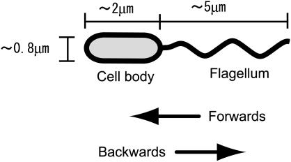
A monotrichous bacterial cell also changes the rotational direction of its flagellum; however, the shape of the flagellar filament does not change. For instance, the filament of Vibrio alginolyticus is covered by a sheath, which may prevent the filament from transforming (8). Because of this geometrical simplicity, the cell can move only backward and forward in a straight line unless some disturbance is introduced. Here, forward motion is defined as motion when the cell body precedes the flagellum, as shown in Fig. 1. In reality, the cells are observed to change direction and swim in a zigzag pattern. There are several theories for the source of these disturbances, which include Brownian motion, deformation of the flagellar filament (9), and deformation of the part (hook) connecting the filament to the motor. In addition, the presence of a boundary should be included as a potentially important factor.
FIGURE 1.
Schematic of a bacterium with a single polar flagellum. The cell consists of a body and a flagellum. The cell body precedes the flagellum in the forward direction.
This study presents a mechanical explanation for the characteristic motions of V. alginolyticus YM4, as observed when the cell swims close to a wall. Because the size of the cell is small, the inertial forces are negligible and the stream lines around the cell are considered to be the same for forward and backward motions irrespective of flow direction. Thus, it is reasonable to expect that the forward and backward motions would be symmetric. However, there are differences in the trajectories of successive forward and backward motions. The results of the numerical analyses conducted here show that the stability in motion differs between forward and backward directions.
The most noticeable difference in the characteristic motion of YM4 cells, for the forward and backward directions, was the swimming speed (10). Also, a difference in the shape of the trajectories was apparent (11). More specifically, for forward motion, the trajectory tends to be straight, whereas for backward motion, the trajectory tends to be circular, especially when the cell moves close to a wall. Experimental investigation has shown that these phenomena are caused by fluid-dynamic interactions between the cell and the rigid boundary rather than by electrochemical or electrostatic interactions (12). Further, numerical simulation has illustrated that the asymmetry between the forward and backward motions is important for bacterial chemotaxis (12).
Fluid-dynamic simulations identifying those orientations that dominate the interaction between the cell and the boundary are expected to improve understanding of the observed motion. Lighthill (13,14) considered the motion of a helical thin film from the perspective of fluid dynamics and proposed suitable resistance coefficients that should be adopted by the resistive force theory for the flagella. The slender body theory, in which a small segment of the flagellum is replaced by a distribution of Stokeslets and dipoles, was used to derive the coefficients. Higdon (15) developed a numerical method based on the slender body theory and calculated the swimming speed of a microorganism consisting of a spherical cell body and a helical flagellum. In this calculation, he took into account the effect of the cell body using analytically obtained image systems. The boundary element method allows for the consideration of arbitrary cell body and flagellum shapes. Phan-Thien et al. (16) calculated the shapes of ideal microorganisms to produce the most efficient swimming. Flores et al. (17) addressed flagellar bundling. The elastic deformation of the flagellum was modeled using a network of springs and the fluid dynamic interaction was modeled using a distribution of the singularities. Fauci and McDonald (18) applied the immersed boundary method to calculate the motion of spermatozoa with beating flagella in the presence of boundaries for a two-dimensional configuration.
Ramia et al. (19) conducted a boundary element analysis to examine the effect of fluid-dynamic interactions on the motion of a microorganism swimming close to a rigid wall. The results indicated that the swimming speed increases by <10% when the microorganism moves closer to the wall and also that the trajectory becomes circular. However, in their calculations, the dimensions of the microorganism were adjusted to ideal values optimized for efficient swimming and consisted of a spherical cell body and a flagellum with a radius of the helix larger than that of the cell body.
The YM4 cell is dissimilar to this ideal microorganism. The cell body is actually a cylinder capped at both ends by hemispheres and the radius of the flagellum helix is smaller than that of the cell body. In this study, the motion of the YM4 cell swimming close to a wall is examined using boundary element analysis. The numerical results obtained reveal that the orientation of the cell with respect to the wall is a strong contributory factor to the difference between the forward and backward motions.
In the sections that follow, the results of initial experiments are summarized. Then, the numerical procedure used to calculate the swimming speed is described and the results detailed. The final section offers an explanation for the observed bacterium motions based on these results.
Brief summary of observed results
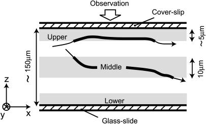
Fig. 2 shows a schematic side view of the trajectories of the cell in a suspension sealed between a glass slide and a coverslip at a distance of ∼150 μm apart. The practical focal depth of the microscope is only ∼10 μm. Thus, we may resolve different layers of interest within the suspension. Let us define a “lower layer” near the slide boundary, an “upper layer” near the coverslip boundary, and a “middle layer” at the center distance between the slide and coverslip boundaries. When the focal point is set to the lower or upper layer, it is expected that the observed motion of the bacteria should be influenced by the boundary. However, for the middle layer, this motion should be free of such influences.
FIGURE 2.
Schematic side view of the paths of bacteria in a chamber. The motion of cells within different focal depth ranges (shown by the gray areas) were observed and the resulting trajectories are shown as thick lines.
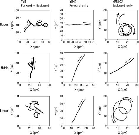
The characteristics of the trajectories of YM4 cells reported previously (11) are reproduced well by the independent observations made here, shown in Fig. 3. For the middle layer, the trajectory of YM4 is almost straight. In contrast, for the upper and lower layers, the trajectories consist of straight parts and circular parts. The trajectories of the mutant strains, YM42 and NMB102, are also shown in Fig. 3. These strains lack the ability to change the rotational direction of the motor. More specifically, the YM42 cells are able to move only forward and the NMB102 cells only backward. The YM42 cell swims in a straight line irrespective of the presence of the wall. In contrast, the NMB102 cell moves in a circular path when close to the wall and a straight line when away from the wall. Given these characteristics, it can be deduced that the straight and circular parts of YM4's trajectory correspond to forward and backward motions, respectively.
FIGURE 3.
Examples of trajectories for V. alginolyticus as observed from the positive z-direction (from the top; defined in Fig. 2). The rows show the various levels, i.e., upper, middle, and lower (see Fig. 2). The columns show the various strains, i.e., YM4 (wild type, able to move forward and backward), YM42 (forward only), NMB102 (backward only).
In addition to differences in trajectory, differences in swimming speed have been reported for forward and backward motions near a wall. More specifically, the speed in the backward direction is greater than that for the forward direction by up to 50% (10,12). Also, in the vicinity of a wall the residence time distribution in the backward motion is broader than that in forward motion (12), which means some of the bacteria tend to stay close to the wall for a longer time when swimming backward than when swimming forward.
Numerical method
The swimming of a bacterium above an infinite plane rigid boundary was treated here as a so-called “outer flow problem” in low Reynolds number fluid dynamics. The numerical method was based on boundary element analysis consistent with those performed in previous studies (19,20).
Because the size of the bacterium is on the order of 1 μm, and the Reynolds number of the associated fluid motion is almost 10−5, the fluid motion is governed by the Stokes equation:
 |
(1) |
where p, μ, u, and x denote the pressure, the viscosity, the velocity vector, and the position vector, respectively.
Because the bacterium swims with no external forces, the free-swimming condition holds:
 |
(2) |
 |
(3) |
where t is the traction vector referring to the surface force per unit area and r is the position vector with an arbitrary origin.
The Green function, used for configurations including an infinite wall (21), is applied here to satisfy the nonslip condition at the wall, i.e., the fluid velocity at the surface is zero.
A nonslip condition is also applied to the surface of the bacterial cell. Both the cell body and flagellar filament are assumed to be rigid bodies. These two rigid bodies rotate relative to each other at the rotary motor interface. The rotary motor and the hook are not modeled here. For these conditions, the velocity of each point on the surface of the cell can be expressed as:
 |
(4) |
where U is the translational velocity at the motor position,  is the cell body angular velocity,
  is the angular velocity of the rotary motor, and the origin of the vector r is chosen at the center of the motor.
The procedure to obtain U and  is as follows. First Eq. 1 was integrated using Green's function methods to obtain a boundary integral equation in terms of the velocity and traction on the bacterial cell surface (see Appendix A). This equation is subsequently discretized by expressing it in terms of the velocities and tractions at nodal points on the surface of the cell boundary element model using coefficient matrices [H] and [G]:
 |
(5) |
Next, the velocities in Eq. 4 are substituted into the left-hand side of Eq. 5. Multiplying both sides by  gives the tractions as functions of U and
  These tractions are then substituted into Eqs. 2 and 3 resulting in an equation with six components corresponding to force (Eq. 2) and torque vectors (Eq. 3), each consisting of three components in Cartesian space. Solving the equation yields U and
  for a given angular velocity of the motor,
  (see Appendix B).
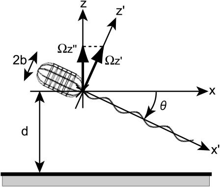
U and  were calculated for various distances from the wall, d, and pitch angles, θ, using the Cartesian coordinate system defined in Fig. 4. The dimensions of the bacterium model were determined by averaging the dimensions of 100 YM4 cells (20). In this calculation, the total number of boundary elements was 226 (see Appendix C). The configuration between the bacterium model and wall changes as the flagellum rotates due to the asymmetry of the helical flagellum. Because the cell proceeds only a short distance during one flagellar rotation, U and
  were averaged for one such rotation.
FIGURE 4.
Boundary element model of a bacterial cell with body width (2b) swimming at a distance (d) from a wall. The coordinate systems xyz and x′y′z′ are shown, as is the pitch angle, θ.
Numerical results
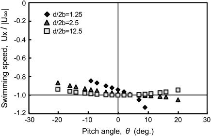
Fig. 5 shows the x component values of the velocity vector as functions of the pitch angle, θ, for various distances from the wall. For small values of θ, this x component dominates the swimming speed. Note that, for the coordinate system defined in Fig. 4, the forward swimming direction for the bacterium cell is in the negative x direction. If the bacterium cell swims at a distance from the boundary of ∼10 times the diameter of the cell, the swimming speed is unaffected by the wall. However, as it swims closer to the wall, the swimming speed varies with θ. When the cell swims parallel to the wall, namely θ = 0, the closer to the wall the cell is, the slower it swims. When the cell swims in an orientation such that the flagellum is close to the wall and the cell body is away from the wall, namely θ > 0, the speed increases. Thus, the swimming speed increases when either the cell swims at a significant distance from the wall or the flagellum interacts with the wall.
FIGURE 5.
Forward swimming speed of the bacterial model as a function of pitch angle. The speed is normalized with respect to the swimming speed in free space,  Parameter d/2b is a measure of the distance from the wall (see Fig. 4). These data should be inverted with respect to the abscissa for the case of backward motion.
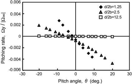
For forward motion, the angular velocity about the y axis, i.e., the pitching rate, is shown in Fig. 6. If the cell swims at a significant distance from the wall, the pitching rate is independent of θ and is negligible. However, if the cell interacts with the wall, the pitching rate is almost proportional to the pitch angle. The proportional constant is negative for forward swimming and increases as the cell swims closer to the wall. Because pitching rate is the time derivative of pitch angle, the negative sign for the proportional constant indicates that the pitching motion for the forward direction has positive damping and is stable. For backward motion, all data are inverted with respect to the horizontal axis, i.e., negative becomes positive and vice versa. It follows, therefore, that the proportional constant becomes positive. Consequently, the pitching motion for the backward direction has negative damping and is unstable.
FIGURE 6.
Pitching rate in forward motion as a function of pitch angle. The rate is normalized using the angular velocity of the cell body in free space, 
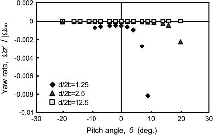
For forward motion, the relationship between the angular velocity about the z axis, the yaw rate, and the pitch angle is shown in Fig. 7. The yaw rate is sensitive to the pitch angle only when the cell swims close to the wall and is oriented with the flagellum close to the wall. In such cases, for forward swimming motion, the yaw rate becomes negative and the resultant trajectory will curve in a clockwise direction when the motion is observed from above. For backward motion, similar to the pitching rate data, the signs of all data are inverted with respect to the horizontal axis. Thus, the yaw rate becomes positive and the resultant trajectory will curve in a counterclockwise direction when the motion is observed from above.
FIGURE 7.
Yawing rate in forward motion as a function of pitch angle.  is the projection of
  onto the z axis as defined in Fig. 4.
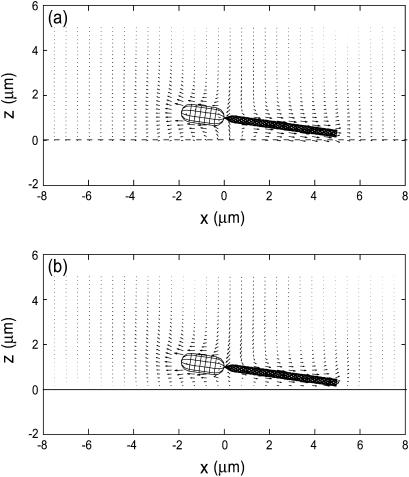
Fig. 8 compares the averaged velocity vectors around the bacterium model between cases in which the bacterium model is in free space and when the model is close to a wall. The vectors are in the x-z plane, and for forward motion with a pitch angle θ = 8°. It is clearly shown that when the fluid motion around the flagellum flows backward, the cell body is propelled in the forward direction. In Fig. 8 b, the magnitudes of the velocity vectors on the wall (z = 0) are zero due to the nonslip condition. The effect of the presence of the wall is small except for the velocity vectors close to the wall.
FIGURE 8.
Averaged velocity field around a bacterium model in the x-z plane. The model moves forward with a pitch angle θ = 8° at a distance from the wall d/2b = 1.25; (a) without a wall, (b) with a wall at z = 0.
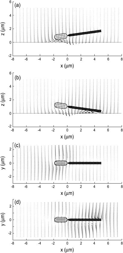
To extract the difference due to the presence of the wall, the velocity field without the wall was subtracted from the velocity field with the wall. The results for the bacterium model with θ = −8° and θ = 8° are shown in Fig. 9. In Fig. 9 a, the cell body moves upward when θ = −8° so that the pitching rate becomes positive, whereas in Fig. 9 b, the flagellum moves upward when θ = 8°, which introduces a negative pitching rate. These velocity vectors are consistent with the pitching rate shown in Fig. 6.
FIGURE 9.
Subtracted velocity field illustrating the effect of a wall at z = 0 on the velocity field. The model moves forward at a distance from the wall d/2b = 1.25. (a) θ = −8°, in the x-z plane, (b) θ = 8°, in the x-z plane, (c) θ = −8°, in the plane that includes the centerline of the flagellum and is parallel to the y axis, (d) θ = 8°, in the plane that includes the centerline of the flagellum and is parallel to the y axis.
In Fig. 9 a, the subtracted velocity vectors around the cell body point to the negative x axis direction, which indicates that the swimming speed decreases if a wall exists. The vectors around the cell body in Fig. 9 b point to the positive x axis direction, although their magnitudes are small. This indicates that the bacterium model swims faster when it encounters a wall and swims at a positive pitch angle, as shown in Fig. 5.
The subtracted velocity vectors shown in Fig. 9, c and d, correspond to the yaw rate shown in Fig. 7. Especially when θ = 8°, the flagellum moves in the negative y axis direction and the cell body moves in the positive direction, which causes the clockwise rotation of the bacterium model when viewed from above.
For backward motion, all the vectors in Figs. 8 and 9 point in the opposite directions because the signs of U and  are inverted from those for forward motion.
DISCUSSION
At any point in time, the signs of U and  for forward motion are opposite to those for backward motion, and their magnitudes are the same. Over a long period, however, the consequent position and posture are different. The numerical results obtained in the previous section represent quasisteady values because the inertial forces are negligible. During an infinitesimal period, the bacterium model in a certain posture with pitch angle θ and distance from the wall d proceeds and rotates with the corresponding velocity U and the angular velocity
  After this period, the model slightly changes its orientation and position, which results in a change in θ and d. Then, in the next instant, the model moves according to U and
  that correspond to the new θ and d. Thus, the motion of the model can be tracked.
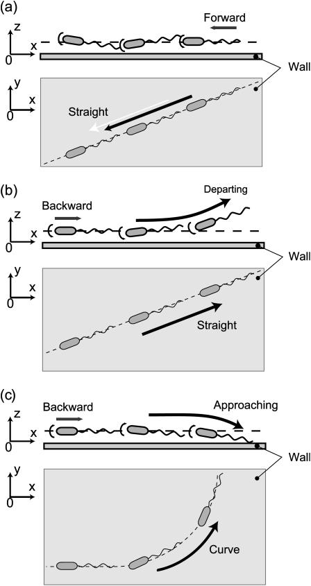
Numerical tracking of the motion, which requires a considerably long computational time, has not yet been conducted. Instead, a qualitative explanation of the motion of a cell close to a wall summarizing the numerical results is presented. A number of diagrammatic representations were generated to explain the experimentally observed differences between the forward and backward motions over a long period. These are shown in Fig. 10.
FIGURE 10.
Images of the motion of a bacterium close to the wall. Forward motion is stable: (a) the cell moves in a straight line maintaining a fixed distance from the wall. Backward motion is unstable: (b) the cell moves in a straight line when departing the wall, and (c) the cell trajectory is curved in a counterclockwise sense as seen from above when approaching the wall.
Because the pitching motion is stable for the parallel forward motion shown in Fig. 10 a (Fig. 6), a bacterium will maintain a fixed distance from the wall and the pitch angle θ will be maintained close to 0°. When θ ≈ 0°, its speed is slower than that achieved in free space due to the presence of the wall (Fig. 5). This does not lead to significant circular motion because the yaw rate is negligible when θ ≈ 0° (Fig. 7).
Backward motion can be classified into two types because the corresponding pitching motion is unstable (Fig. 6): one is “departing”, which is depicted in Fig. 10 b, where the pitch angle θ is negative and continues to decrease unless the cell is at a distance from the wall (e.g., d/2b = 12.5); and the other is “approaching,” which is shown in Fig. 10 c, where the pitch angle θ is positive and continues to increase.
For departing motion, cell motion is influenced very little by the wall because the cell is steadily increasing its distance from the wall. It swims almost in a straight line (Fig. 7, θ < 0°) at an averaged speed nearly equal to that achieved in free space (Fig. 5).
For approaching motion, the cell approaches very close to the wall and the averaged speed is larger than that achieved in free space because the orientation places the flagellum close to the wall (Fig. 5). The positive pitch angle induces rotation in the yaw direction which, in turn, results in a circular trajectory in the counterclockwise direction when viewed from above (Fig. 7).
These diagrammatic representations are consistent, at least qualitatively, with the observed circular trajectories when the cells swim backward close to the wall. They are also consistent with the speed in the backward direction exceeding that in the forward direction. Moreover, they lead us to understand that the broadness in the residence time distribution for the backward direction is due to the unstable motion. The approaching cells tend to stay longer near the wall than the departing cells do. Therefore, we conclude that the unusual characteristics of the motions observed are mainly caused by fluid-dynamic interactions between the cell and the rigid boundary when the cell has a nonparallel orientation relative to the boundary. This representation may be verified if the pitch angle is measured along with the swimming speed and trajectory in experiments, although the direct measurement of θ seems to be very difficult.
The diagrammatic representation for approaching cells suggests that the flagellum collides with the wall in approaching motion and sometimes touches the wall during motion with a circular trajectory. This was not considered in the calculation here and so quantitative agreement with the experiments is not expected. The hook portion of the flagellum is assumed to be flexible, and this flexibility allows the flagella of peritrichous bacteria to form a bundle. The hook portion bend is sometimes observed when the YM4 cell changes its swimming direction. This flexibility was also not taken into account in this analysis. However, the bending is only observed at the instant of direction change. The flagellum is not observed bending at the hook part during forward or backward motion (10). However, there is another opportunity for the hook to deform slightly because the axis of the flagellar helix is not generally collinear with the centerline of the cell body. This may change the quantitative values calculated in this article. To obtain quantitatively exact values, the exact relative motion of the cell body and the flagellum should be included in the calculation, which requires unknown factors such as bending stiffness, torsional stiffness, and homogeneity. The results presented here provide a qualitative explanation of the observed bacterial motion.
The asymmetry observed in the motion of bacteria has an important bearing on how far the bacteria can spread in a given time. This was examined in a previous study (12) in which a numerical simulation was performed for chemotactic behavior of bacteria using the asymmetric parameters obtained from observation. It is now reasonable to suggest that such a model should include the effect of the fluid-dynamic interactions with a boundary on the diffusivity of the bacteria. The asymmetry increases the probability of bacteria remaining near a wall and forming a biofilm on it. This may answer the question of why bacterial populations gather on the surface of a wall, even if that wall is inorganic and unimportant to their chemotaxis.
According to the numerical results presented here, the closer to a wall a cell is, the slower it swims. This is contrary to results reported by Ramia et al. (19) and is due to differences between the shape of real bacteria and the idealized microorganism shape used in that study that possesses a small spherical cell body and a large flagellum. As is specified in Eqs. 2 and 3, the net force should balance out during motion. The presence of a wall simultaneously increases the drag force exerted on the cell body and the propulsive force of the flagellum. For real bacteria, the former of these two forces is dominant. However, for the idealized microorganisms of the previous study (19), the latter force is dominant.
Berg and Turner (22) reported a circular trajectory for the E. coli cell, which has a cell size smaller than the flagellum size. Because E. coli is peritrichous, the nature of its motion differs from that of monotrichous bacteria. More specifically, the cell swims in a way in which the cell body precedes the flagellar bundle, so it is considered to move forward, as described in the introduction. Ramia et al. (19) identified the circular trajectory for singly flagellated microorganisms in forward motion. This suggests that stability depends on the ratio of the cell body to flagellum size, a notion that warrants investigation in the near future.
Acknowledgments
The authors thank Y. Takano, S. Kudo, N. Kanamori, and M. Ichiba for their helpful discussions and also M. Homma for the bacterial strains.
This research was partly supported by the Japan Society for the Promotion of Science (17560150).
APPENDIX A: BOUNDARY INTEGRAL EQUATION
The procedure to derive the boundary integral equation for half space is the same as that used in previous studies (19,20).
Multiplying the right equation of Eq. 1 by a vector v(x, y), the left equation of Eq. 1 by a scalar  and then integrating the sum of the two for the fluid domain V produces
 |
(A1) |
Here, the term  which is zero from the right equation of Eq. 1, is added to derive a boundary integral equation in terms of velocity and traction. Applying Gauss's theorem to Eq. A1 yields
 |
(A2) |
Here,  is the traction expressed by
  and
and  instead of
  and
and  The surface for the integration of
  in Eq. A2 includes both the infinite wall and the bacterium model. When a set of elementary solutions satisfying the nonslip condition on the infinite wall is chosen for the vector
  and the scalar
  we do not need to integrate for the infinite wall surface, only for the surface of the bacterium model. The explicit forms of such elemental solutions are given by Blake (21) and Ramia et al. (19). Thus, Eq. A2 is written in terms of velocity and traction:
 |
(A3) |
Here S is the surface of the bacterium model. If the position x is chosen on the surface, Eq. A3 yields a boundary integral equation. The first term on the right-hand side of Eq. A3 should be evaluated using Cauchy's principal value as  because
  has a singularity that does not disappear after the integration as
  The boundary integral equation is
 |
(A4) |
where
 |
Equation A4 is transformed into a discretized boundary integral equation in terms of the velocities and the tractions of node points of boundary elements, that is Eq. 5.
APPENDIX B: DEPENDENCE OF THE CALCULATED RESULTS ON ω
The final form of the equation for U and  is an algebraic equation:
 |
(B1) |
where the matrix  is determined from the matrices
  and the positions of each node point. In the calculation,
  was given in the coordinate system fixed to the cell body. ω was held constant whereas θ and d were varied. From Eq. B1, the calculated U and
  are proportional to
  When the results are normalized by any linear or angular speed in the calculation, as is done in Figs. 5– 7, the nondimensional values are independent of
The torque of the motor is evaluated from the resultant U and  Because the torque is also proportional to ω, U and
  can be calculated when the torque of the rotary motor is held constant. The data are not shown here, but the results for constant torque are not significantly different from the data for a constant
APPENDIX C: BOUNDARY ELEMENT MODELING
The surfaces of both the cell body and the flagellum were discretized as boundary elements. Isoparametric quadrilateral elements with eight node points were adopted for all the elements. The cell body was modeled as a circular cylinder with both ends capped by hemispheres, and the flagellum was modeled as a thin twisted circular cylinder. The boundary elements on the flagellum were adjusted to avoid becoming highly skewed. The numbers of elements for the cell body and the flagellum were 70 (212 nodes) and 156 (470 nodes), respectively.
Kousou Nakata's present address is Shin Nippon Air Technologies, Tokyo 103-0021, Japan.
Kensaku Baba's present address is Sakata Inx, Noda 270-0235, Japan.
References
- 1.Lewis, D. M. 2003. The orientation of gyrotatic spheroidal micro-organisms in a homogeneous isotropic turbulent flow. Proc. R. Soc. London Ser. A. 459:1293–1323. [Google Scholar]
- 2.Vanesa, M., T. Goto, and T. J. Pedley. 2003. Nutrient uptake by a self-propelled steady squirmer. Q. J. Mech. Appl. Math. 56:65–91. [Google Scholar]
- 3.Macnab, R. M. 1987. Motility and chemotaxis. In Escherichia coli and Salmonella typhimurium. F. C. Neidhardt et al., editors. ASM Press, Washington, DC. 732–759.
- 4.Blair, D. F. 1995. How bacteria sense and swim. Annu. Rev. Microbiol. 49:489–532. [DOI] [PubMed] [Google Scholar]
- 5.McCarter, L. L. 2001. Polar flagellar motility of the Vibrionaceae. Microbiol. Mol. Biol. Rev. 65:445–462. [DOI] [PMC free article] [PubMed] [Google Scholar]
- 6.Macnab, R. M., and M. K. Ornston. 1977. Normal-to-curly flagellar transitions and their role in bacterial tumbling. Stabilization of an alternative quaternary structure by mechanical force. J. Mol. Biol. 112:1–30. [DOI] [PubMed] [Google Scholar]
- 7.Turner, L., S. R. William, and H. C. Berg. 2000. Real-time imaging of fluorescent flagellar filaments. J. Bacteriol. 182:2793–2801. [DOI] [PMC free article] [PubMed] [Google Scholar]
- 8.Furuno, M., T. Atsumi, T. Yamada, S. Kojima, N. Nishioka, I. Kawagishi, and M. Homma. 1997. Characterization of polar-flagellar-length mutants in Vibrio alginolyticus. Microbiology. 66:3632–3636. [DOI] [PubMed] [Google Scholar]
- 9.Takano, Y., K. Yoshida, S. Kudo, M. Nishitoba, and Y. Magariyama. 2003. Analysis of small deformation of helical flagellum of swimming Vibrio alginolyticus. JSME Int. J. Ser. C. 46:1241–1247. [Google Scholar]
- 10.Magariyama, Y., S. Masuda, Y. Takano, T. Ohtani, and S. Kudo. 2001. Difference between forward and backward swimming speeds of the single polar-flagellated bacterium, Vibrio alginolyticus. FEMS Microbiol. Lett. 205:343–347. [DOI] [PubMed] [Google Scholar]
- 11.Kudo, S., N. Imai, M. Nishitoba, S. Sugiyama, and Y. Magariyama. 2005. Asymmetric swimming pattern of Vibrio alginolyticus cells with single polar flagella. FEMS Microbiol. Lett. 242:221–225. [DOI] [PubMed] [Google Scholar]
- 12.Magariyama, Y., M. Ichiba, K. Nakata, K. Baba, T. Ohtani, S. Kudo, and T. Goto. 2005. Difference in bacterial motion between forward and backward swimming caused by the wall effect. Biophys. J. 88:3648–3658. [DOI] [PMC free article] [PubMed] [Google Scholar]
- 13.Lighthill, J. 1996. Helical distributions of stokeslets. J. Eng. Math. 30:35–78. [Google Scholar]
- 14.Lighthill, J. 1976. Flagellar hydrodynamics. SIAM Review. 18:161–230. [Google Scholar]
- 15.Higdon, J. J. L. 1979. A hydrodynamic analysis of flagellar propulsion. J. Fluid Mech. 90:685–711. [Google Scholar]
- 16.Phan-Thien, N., T. Tran-Cong, and M. A. Ramia. 1987. A boundary-element analysis of flagellar propulsion. J. Fluid Mech. 90:533–549. [Google Scholar]
- 17.Flores, H., E. Lobaton, S. Mendez-Diez, S. Tlupove, and R. Cortez. 2005. A study of bacterial flagellar bundling. Bull. Math. Biol. 67:137–168. [DOI] [PubMed] [Google Scholar]
- 18.Fauci, L., and A. McDonald. 1995. Sperm motility in the presence of boundaries. Bull. Math. Biol. 57:679–699. [DOI] [PubMed] [Google Scholar]
- 19.Ramia, M. D., L. Tullock, and N. Phan-Thien. 1993. The role of hydrodynamic interaction in the locomotion of microorganisms. Biophys. J. 65:755–778. [DOI] [PMC free article] [PubMed] [Google Scholar]
- 20.Goto, T., S. Masuda, K. Terada, and Y. Takano. 2001. Comparison between observation and boundary element analysis of bacterium swimming motion. JSME Int. J. Ser. C. 44:958–963. [Google Scholar]
- 21.Blake, J. R. 1971. A note on the image system for a stokeslet in a no-slip boundary. Proc. Camb. Phil. Soc. 70:303–310. [Google Scholar]
- 22.Berg, H. C., and L. Turner. 1990. Chemotaxis of bacteria in glass capillary arrays. Biophys. J. 58:919–930. [DOI] [PMC free article] [PubMed] [Google Scholar]


