

Abstract
Staphylococcal γ-haemolysin HlgA–HlgB forms a β-barrel transmembrane pore in cells and in model membranes. The pore is formed by the oligomerization of two different proteins and a still debated number of monomers. To clarify the topology of the pore, we have mutated single residues – placed near the right and left interfaces of each monomer into cysteine. The mutants were labelled with fluorescent probes, forming a donor–acceptor pair for FRET (fluorescence resonance energy transfer). Heterologous couples (labelled on complementary left and right interfaces) displayed a marked FRET, suggesting extensive HlgA–HlgB or HlgB–HlgA contacts. Heterologous control couples (with both components labelled on the same side) showed absent or low FRET. We found the same result for the homologous couple formed by HlgA [i.e. HlgA–HlgA in the presence of wt (wild-type) HlgB]. The homologous HlgB couple (HlgB–HlgB labelled on left and right interfaces and in the presence of wt HlgA) displayed a transient, declining FRET, which may indicate fast formation of an intermediate that is consumed during pore formation. We conclude that bicomponent pores are assembled by alternating heterologous monomers.
Keywords: fluorescence resonance energy transfer (FRET), leucotoxin, oligomerization, pore-forming toxin, protein–protein interaction, Staphylococcus aureus
Abbreviations: ALEXA-488, ALEXA Fluor 488 C5 maleimide; ALEXA-546, ALEXA Fluor 546 C5 maleimide; Chol, cholesterol; EM, electron microscopy; FRET, fluorescence resonance energy transfer; GST, glutathione S-transferase; HlgAla, HlgA S22C; HlgAlb, HlgA Q202C; HlgAr, HlgA S148C; HlgBl, HlgB S27C; HlgBr, HlgB R155C; LUV, large unilamellar vesicle; PC, phosphatidylcholine; PFT, pore-forming toxin; RBC, red blood cell; RRBC, rabbit RBC; wt, wild-type
INTRODUCTION
Staphylococcus aureus is a major human pathogen, frequently isolated both from community and nosocomial infections. Concern about staphylococcal strains is growing as they are developing multiple antibiotic resistances [1–3]. Among the several virulence factors, α-toxin and the bicomponent leucotoxins, i.e. the γ-haemolysins and Panton–Valentine leucocidins are the most important. These are PFTs (pore-forming toxins) that belong to the transmembrane β-barrel family [4,5]. They target human polymorphonuclear cells, monocytes, macrophages and RBCs (red blood cells) and, in all cases, they insert in the lipid bilayers [6–9]. By forming pores in the plasma membrane of leucocytes, they weaken the host immune response and provide access to the nutrients stored therein [10]. The active form of bicomponent toxins is a membrane-bound oligomer in which two different, separately secreted cysteine-less components are present. These components are classified into two different subfamilies, called S and F [4,10]. The F components (six members known to date) share 70–80% sequence identity, while in S components (seven members known) the identity ranges from 60 to 80% [11]. The two S and F subfamilies also share 20–30% sequence identity among themselves and with the α-toxin, thus forming a unique family.
A precise characterization of the molecular events underlying the biological activity of these PFTs is important not only for understanding bacterial virulence, but also for clarifying the basic mechanisms of protein–protein and protein–membrane interaction, and for the design and development of new inhibitor molecules that can interfere with the pore function, acting as novel antibiotics [12].
Previous studies have shown that the pore formed by bicomponent toxins contains the two components in a 1:1 average molar ratio [13]. The number of subunits forming the pore, however, is not yet firmly established. The number of subunits has been proposed to be either six [13–15], seven [16] or eight [9].
The three-dimensional structure of the monomeric, water-soluble form has been determined both for the F component (HlgB, PDB code 1LKF [17], and LukF-PV, PDB code 1PVL [18]) and the S component (LukS-PV, PDB code 1T5R [11]). They all are quite similar and almost superimposable on the core structure of the α-toxin protomer when extracted from the heptamer that it forms in a hydrophobic environment, PDB code 7AHL [19]. The major difference is in the folding of the β-hairpin which assembles to constitute the transmembrane β-barrel. In fact, using the α-toxin heptamer as a template, we attempted to construct a hexameric three-dimensional model of the bicomponent γ-haemolysins channel that correctly predicted the electrical properties and the selectivity [6]. This model demonstrated that both components were equally important in their contribution to the nature of the pore lumen. However, the topology of the monomer distribution inside the complex has not yet been rigorously demonstrated. Recently, single-molecule fluorescence microscopy was used to investigate the intermediates that occur during the assembly of the γ-haemolysins A and B on RBC membranes [20]. Analysis of the FRET (fluorescence resonance energy transfer) between different dyes attached to the monomeric subunits suggested that pores are formed via a highly co-operative assembly of heterologous dimers (HlgA–HlgB). However, because the label was placed at a single position for each component, i.e. at the centre of the monomer, it was not possible to distinguish between the two feasible heterologous dimers: HlgA–HlgB and HlgB–HlgA. Therefore the question remains open of whether these pores might provide either four different interfaces, i.e. two heterologous (HlgA–HlgB and HlgB–HlgA) and two homologous (HlgA–HlgA and HlgB–HlgB), or only the two heterologous couples. The first possibility would appear if the two heterologous dimers (HlgA–HlgB and HlgB–HlgA) can assemble in a random order, whereas the second would derive only if a sequential assembly of HlgA–HlgB (or HlgB–HlgA) dimers is possible. The latter hypothesis is favoured by genetic considerations on the possible evolution of these toxins [9,10] and in terms of number of contacts that have to be accommodated.
To address this specific question, we studied in more detail the monomer–monomer interactions arising inside the lipid-bound complex of γ-haemolysins A and B. We individually mutated into cysteine two amino acids of each component, choosing those placed near the putative right and left monomer–monomer interface, and introduced suitable markers to form a FRET couple. These amino acids may report about the establishment of border interactions. The possible formation of HlgA–HlgB, HlgB–HlgA, HlgB–HlgB and HlgA–HlgA interfaces was tested. The first two appeared to a large extent in the steady-state complex, suggesting that heterologous interactions are preferred to the homologous ones.
EXPERIMENTAL
Materials
Egg PC (phosphatidylcholine) from Avanti Polar Lipids (Alabaster, AL, U.S.A.) and Chol (cholesterol) from Fluka (Buchs, Switzerland) were used for LUV (large unilamellar vesicle) preparation. ALEXA-488 (ALEXA Fluor 488 C5 maleimide; a fluorescein derivative) and ALEXA-546 (ALEXA Fluor 546 C5 maleimide; a rhodamine derivative) were purchased from Molecular Probes (Eugene, OR, U.S.A.). Calcein, EDTA and Sephadex G-50 medium were obtained from Sigma (Milan, Italy) and Triton X-100 was from Merck (Darmstadt, Germany).
Bacterial strains and vectors
Epicurian Coli® XL1-Blue cells (Stratagene, Amsterdam, The Netherlands) were used as recipient cells after site-directed mutagenesis of recombinant plasmids. Escherichia coli BL21 was used for overexpression of the pGEX-6P-1 GST (glutathione S-transferase)-fusion leucotoxins as recommended (GE, Amersham Biosciences) [21].
Construction and purification of point mutated X-Cys mutants
The choice of amino acid mutated to cysteine is described in detail in the first subsection of the Results section. Open reading frames of the secreted HlgA and HlgB encoding genes were previously cloned into the expression vector pGEX-6P1 [21]. Recombinant HlgA and HlgB and the five γ-haemolysin mutants were further obtained by site-directed mutagenesis and purified as described previously [21,22]. After removing the GST tag with PreScission® Protease (GE, Amersham Biosciences), HlgA proteins were further purified using cation-exchange FPLC (HlgA) MonoS® chromatography (GE, Amersham Biosciences) [23]. Homogeneity was checked using SDS/PAGE before proteins were stored at −80 °C.
Determination of the haemolytic activity
Rabbit RBCs (RRBCs) were used to test mutant activity before and after labelling. RRBCs were obtained from fresh rabbit blood as described earlier [13]. Haemolytic activity was determined following the attenuance at 650 nm in a 96-well microplate reader (UVMax; Molecular Devices, Sunnyvale, CA, U.S.A.) for 45 min. Toxins were 2-fold serially diluted in the same buffer (30 mM Tris/HCl, 100 mM NaCl and 1 mM EDTA, pH 7.0) used for washing. RRBCs, at a 0.13% (v/v) concentration, were added immediately before starting the kinetic measurements. The percentage of haemolysis was calculated as 100(Di–Df)/(Di–Dw), where Di and Df are the attenuances at the beginning and the end of the reaction, and Dw is the attenuance after the complete lysis of cells in pure water.
Permeabilization of lipid vesicles
LUVs comprising PC/Chol (1:1 molar ratio) were used to check the capability of labelled and non-labelled mutants to form active pores in model membranes. The same lipid composition was chosen for FRET experiments. LUVs loaded with 80 mM calcein (a self-quenching condition) were obtained by pneumatic extrusion through two stacked polycarbonate filters with 100 nm pores. LUV diameter was checked by dynamic light scattering using a Malvern ZetaSizer3 (Malvern, U.K.) as described in [24], and was found to be between 107 and 128 nm. The untrapped dye was removed by gel filtration on a microcolumn loaded with Sephadex G-50 gel pre-equilibrated with 10 mM Tris/HCl, 20 mM NaCl and 0.1 mM EDTA (pH 7.0). The toxins were 2-fold serially diluted in the same buffer (10 mM Tris/HCl, 20 mM NaCl and 0.1 mM EDTA, pH 7.0) used for gel filtration. The maximal concentration of protein was 100 nM for each component. Permeabilization was assayed with a fluorescence microplate reader (Fluostar; BMG LABTECH, Offenburg, Germany). Lipid concentration was 5 μM uniformly. The fluorescence intensity at time t, Ft, was converted into the percentage of calcein released by comparing it with the maximum signal, Fm, obtained after the addition of 1 mM Triton X-100 according to: R(%)=100(Ft–Fi)/(Fm–Fi), where Fi is the initial fluorescence before the addition of the toxins.
Labelling of the mutants with fluorescent probes
The fluorescent probes were diluted in water just prior to use and added in small volumes to the mutant stock. During the labelling reaction, the concentration of mutants ranged between 25 and 80 μM. A probe to protein molar ratio of 20:1 was used. The labelling solution was immediately protected from light and the reaction mixture was incubated for 2 h in a thermomixer at 22 °C (room temperature). Excess reagent was then removed by gel filtration on a Sephadex G-50 microcolumn equilibrated with 10 mM Hepes (pH 7.0). Four protein-containing fractions were usually collected. The degree of labelling, estimated from the absorption spectra, ranged from 80 to 100%. The molar absorption coefficients (ϵ) used were 38910 M−1·cm−1 for HlgA wt (wild-type) and HlgA mutants and 57180 M−1·cm−1 for HlgB wt and HlgB mutants, both at 280 nm; 72000 M−1·cm−1 for ALEXA-488 at 493 nm and 93000 M−1·cm−1 for ALEXA-546 at 554 nm. The characteristic Förster distance for this donor–acceptor pair is ≈50 Å (1 Å=0.1 nm) [25].
FRET measurements
FRET measurements were carried out using a photon counting fluorimeter (SPEX FluoroMax, Horiba Jobin Yvon, Milan, Italy). Direct excitation of ALEXA-488 (donor) was achieved at 490 nm and the fluorescence emission, in the presence of ALEXA-546 (acceptor), was recorded between 500 and 600 nm with both excitation and emission slits set at 1 nm. The concentration of the two toxin components in these experiments was 300 nM in 10 mM Tris/HCl, 20 mM NaCl and 0.1 mM EDTA (pH 7.0). Changes in donor fluorescence emission (with maximum at 516 nm) and acceptor emission (maximum at 570 nm) were recorded for approx. 1.5 h after the addition of PC/Chol vesicles. A spectrum was recorded every 3 min. The FRET development was established as follows: (i) after subtracting control signals from similar experiments in which only one of the labelled components was present [whereby FRET was prevented and photobleaching or environmental effects could be corrected for Ft–Ft(a+d)] and (ii) after subtracting the first measure after LUV addition to each FRET spectrum, Ft–F0.
RESULTS
Choosing the left and right interface mutants
To monitor the possible formation of HlgA–HlgB, HlgB–HlgB and HlgA–HlgA interfaces in the γ-haemolysin pore, we constructed HlgA and HlgB mutants bearing a single cysteine residue at a position near the monomer–monomer interface formed during the pore assembly. Those positions were chosen in accordance with the crystallographic data and modelling, using a putative γ-haemolysin hexamer to help us in the choice. Such a model has already been successfully used to predict the groups exposed inside the lumen of the pore [6].
In this way, at least one amino acid was chosen on both the right and left interfaces of each γ-haemolysin component (Figure 1). Right and left were defined by looking at the monomer from the centre of the pore lumen by viewing it from the cap side of the mushroom-shaped structure. The right side residues HlgA Ser148 (HlgAr) [11] and HlgB Arg155 (HlgBr) were chosen. They correspond to Ser159 of α-toxin, which is placed at the end of strand 9 [19]. The left side residues, HlgA Ser22 (HlgAla) and HlgB Ser27 (HlgBl), correspond to Tyr28 of α-toxin, which is near His35 in the β-sandwich domain of α-toxin. It is located at a crevice formed by strand 6 and the loop between strands 9 and 10 of the neighbouring protomer [19]. An additional left-side residue, HlgA Gln202 (HlgAlb, which corresponds to Ser221 of α-toxin), was used because it was found to be more water-exposed than HlgA Ser22, albeit located very near it in the rim domain at the expected monomer–monomer interface. The amino acids were chosen to allow the right side residue of a protomer and the left side residue to be close enough to give transfer, yet not so close as to prevent oligomerization or pore formation. Based on our α-toxin hexameric model, the approximate distances (see dc in Table 2) between Cα of the left and right side residues are: 10 Å for the left/right position (HlgAlb–HlgBr); 15 Å for the left/right or right/left positions (HlgAla–HlgBr or HlgAr–HlgBl, respectively); 34 Å for the right/right position (HlgAr–HlgBr); 39 Å for the left/left position (HlgAla–HlgBl); 46Å for the HlgB right/left position (HlgBr–HlgBl); and 38 Å for the HlgA right/left position (HlgAr–HlgAlb).
Figure 1. Schematic diagram of the FRET planning.

The three-dimensional model of the possible organization of HlgA and HlgB components inside the pore and localization of the single cysteine residue introduced near the protomer–protomer interfaces. HlgA protomers are shown in dark grey and HlgB protomers in light grey. Highlighted residues are Ser22 (HlgAla), Gln202 (HlgAlb) and Ser148 (HlgAr) of HlgA, and Ser27 (HlgBl) and Arg155 (HlgBr) of HlgB. The corresponding names of the mutants are reported in parentheses. The mutated residues correspond to Tyr28, Ser221 and Ser159 of α-toxin, which were used to generate this image.
Table 2. Crystallographic and calculated distances.
Comparison between the monomer–monomer crystallographic distances (dc) calculated from the putative γ-haemolysin pore [6] based on the α-toxin pore [19] and the monomer–monomer distances obtained by FRET (de) (see the Appendix). Both values are in Å. E is the degree of transfer calculated as described in the Appendix. Mean values are averaged over two to four different experiments; standard errors on E are 10–15%, which lead to 20–30% error on de.
| FRET couple | E | dc | de |
|---|---|---|---|
| HlgAr+HlgBl | 0.954 | 15 | 32 |
| HlgAla+HlgBr | 0.600 | 15 | 49 |
| HlgAlb+HlgBr | 0.432 | 10 | 55 |
| HlgAla+HlgBl | 0.360 | 39 | 58 |
| HlgAr–HlgAlb+HlgB | 0.079 | 38 | 80 |
| HlgAr+HlgBr | 0.060 | 34 | 84 |
The five derived X-Cys mutants are HlgA S22C (HlgAla) or HlgA Q202C (HlgAlb), and HlgA S148C (HlgAr), HlgB S27C (HlgBl) and HlgB R155C (HlgBr). These mutants were labelled with maleimide fluorescent probes (ALEXA-488 and ALEXA-546), and used as donor–acceptor pairs for FRET measurements.
Haemolytic and permeablizing activity
It was important to ascertain whether the mutants produced were active when combined with heterologous wt or mutated proteins before and after the chemical modification with the fluorescent probes. Therefore we measured their lytic activity on RRBCs, which are particularly sensitive to these toxins [13]. Haemolysis was measured for the mutants, labelled or not, in all the couple combinations used for FRET experiments, as well as coupled with unlabelled wt components. In Table 1, we report activity expressed as 1/C50, where C50 is the toxin concentration that causes 50% haemolysis.
Table 1. Haemolytic and permeabilizing activity of the labelled and unlabelled mutants.
| Haemolytic activity 1/C50 (nM−1) | Permeabilizing activity 1/C30 (pM−1) | |||
|---|---|---|---|---|
| Toxin | Unlabelled | Labelled | Unlabelled | Labelled |
| HlgA+HlgB | 4.21±0.08 (3)* | − | 260±8 (2) | − |
| HlgAla+HlgB | 1.65±0.01 (2) | 1.13±0.50 (5) | 126 (1) | 319±18 (5) |
| HlgAlb+HlgB | n.d.† | n.d. | 90±4 (2) | n.a.‡ (2) |
| HlgAr+HlgB | 2.10±0.04 (6) | 2.94±0.40 (4) | n.a. (3) | 75±7 (8) |
| HlgA+HlgBl | 3.94±0.19 (4) | 5.1±0.10 (2) | 189±0.1 (2) | 45±8 (10) |
| HlgA+HlgBr | 3.11±1.00 (4) | 4.1±0.01 (3) | n.a. (1) | 100±8 (8) |
| HlgAla+HlgBl | 1.34±0.03 (2) | n.d. | n.d. | n.d. |
| HlgAr+HlgBr | 1.1 (1) | 4.53±0.10 (2) | n.d. | 1.0 (1) |
| HlgAla+HlgBr | 0.73±0.03 (2) | 0.54±0.01 (2) | n.a. (1) | 9.0±1 (3) |
| HlgAlb+HlgBr | 0.83±0.02 (2) | 12.0±1.0 (2) | 43±1 (2) | 111±1 (2) |
| HlgAr+HlgBl | 2.05±0.50 (2) | 10.1±5.2 (2) | 5.0±0.1 (2) | 23±4 (5) |
| HlgAla–HlgAr+HlgB | n.d | 4.74±0.02 (2) | n.d | n.a (2) |
| HlgAlb–HlgAr+HlgB | 0.90±0.10 (2) | 55.0 (1) | n.d. | 10±4 (2) |
| HlgA+ HlgBl–HlgBr | 0.86±0.03 (2) | 20.4±5.9 (2) | n.d. | 158±7 (2) |
*The number of repetitions is reported in parentheses.
†n.d., not determined.
‡n.a., not active.
The substitution of the left and right side amino acids did not substantially affect the activity of the mutants. All the mutant couples were slightly less active than the wt, whereas in three cases (HlgAlb–HlgBr, HlgAlb–HlgAr and HlgBl–HlgBr) a significant increase in activity was found if the mutant was labelled. Furthermore, all the mutants remained haemolytic at nanomolar concentrations, both before and after labelling. We also observed that none of the mutants exhibited any difference in haemolytic activity after an overnight preincubation with 20× molar excess of dithiothreitol, suggesting that no disulphide-bond promoted dimer was formed (results not shown). Moreover, no dimers (under non-reducing conditions) were recognized by SDS/PAGE (results not shown).
To avoid interference arising from cell proteins, the FRET experiments described below were performed using LUVs comprising purified lipids. We tested the pore-forming activity of each couple in this model membrane by measuring their ability to induce calcein release from PC/Chol LUVs. This is the most appropriate lipid composition according to [13]. These results are also included in Table 1 and confirmed that the labelled mutants could permeabilize the lipid vesicles. Only the labelled couple HlgAla–HlgAr was inactive. Therefore this couple was not used in FRET analysis. To test HlgA–HlgA interaction, we decided to introduce the other left mutation, HlgA Q202C (HlgAlb), that retained pore-forming activity on liposomes.
Monomer–monomer interactions: FRET results
The aim of our FRET experiments was to determine whether the labelled amino acid residues become neighbours during pore assembly or not. This implies monitoring the donor and the acceptor fluorescence during the whole kinetic activity of the toxin interaction with the vesicles. Figure 2 shows a typical experiment. HlgAr and HlgBl were labelled with donor and acceptor respectively. They were added to a buffer solution (10 mM Tris/HCl, 20 mM NaCl and 0.1 mM EDTA, pH 7.0) at equimolar concentration and the basal fluorescence, in the absence of pores, was measured. At zero time, LUVs were added and, thereafter, spectra were regularly recorded. The emission spectrum at time 105 min is represented by the solid line in Figure 2(A). Fluorescence changes following the interaction with LUVs are evident in Figure 2(B), where the differences between the spectra taken at time t and time 0 are reported. In this experiment, it is evident that the fluorescence emitted by the donor decreases while that of the acceptor increases, indicating an effective energy transfer. To take into account the possible variations in fluorescence that could arise from the interaction of the single components with the lipid matrix, or for the possible photobleaching, we carried out an additional investigation. Two more experiments were done in which either donor-labelled HlgAr was mixed with unlabelled HlgBl or unlabelled HlgAr was mixed with acceptor-labelled HlgBl (shown in Figure 2A, dotted and dashed lines). The extent of energy transfer at any time t was then determined by subtracting each of the two spectra in which only one component was labelled from the spectrum with both components labelled. These differential spectra are shown in Figure 2(C) and represent the difference in the donor (or acceptor) emitted fluorescence in the case that the acceptor (or the donor) was present or not. It is obvious that the tendency is the same as in Figure 2(B): the fluorescence emitted by the donor decreases with time, while that of the acceptor increases, indicating a genuine energy transfer. The difference in the shape of the donor spectrum is due to the fact that emission of the donor, in the absence of the acceptor, is broader than in its presence. Such a discrepancy is not always present with the different mutants, whereas the time course of the fluorescence changes, obtained with the two methods illustrated here, is always the same. Even though in most cases we report only results calculated with the first procedure (i.e. the difference from the initial spectrum), the method of the three experiments (mixed donor–acceptor minus donor alone and acceptor alone) was always performed and gave similar results.
Figure 2. Fluorescence of labelled HlgA–HlgB couples in the presence of lipid vesicles.

(A) Emission spectra of HlgA S148C (HlgAr) and HlgB S27C (HlgBl) labelled with donor (D) and acceptor (A) ALEXA fluorophores respectively. The excitation wavelength was 490 nm for each experiment (excitation and emission slits were 1 nm). The labelled couple was premixed in a cuvette at a molar concentration of 300 nM for each component. Thereafter, LUVs were added at a final lipid concentration of 4 μM. The solid line is the spectrum taken 105 min after LUV addition. The dashed line is the corresponding result when only the HlgA component (HlgAr) is labelled and used together with unlabelled HlgBl. The dotted line is the corresponding result when only the HlgB component (HlgBl) is labelled and mixed with unlabelled HlgAr. (B) Fluorescence changes that ensue during the development of the interaction of the γ-haemolysins with the added LUV. Each spectrum is the difference between the spectrum taken at time t and time 0 (i.e. immediately after the addition of the vesicles). (C) Fluorescence changes observed as difference from controls. In this case, each spectrum was obtained by subtracting the two control spectra from the spectrum in which both components are labelled. All the spectra were taken at the same time t. In the two control experiments only one component was labelled. In (B and C), the time in minutes is indicated next to each trace.
Having determined that, upon interaction with the lipid vesicles, the couple HlgAr–HlgBl gives rise to a marked energy transfer, we investigated the other possible combinations. All the interactions of HlgA are shown in Figure 3. HlgAla again gave strong energy transfer with the complementary component HlgBr (Figure 3A). Instead, minimal transfer was observed for HlgAlb with HlgAr and HlgAla with HlgBl, as shown in Figures 3(B) and 3(C) respectively. When considering the two mutants of the HlgA component, left and right labelled as acceptor and donor respectively, they were added in equimolar amounts and supplemented with an equivalent total amount of wt HlgB as counterpart (Figure 3B).
Figure 3. Fluorescence changes during the interaction of HlgAl and different partners with LUVs.

HlgA Q202C (HlgAlb) was coupled with one among HlgB R155C (HlgBr, A), HlgB wt and HlgA S148C (HlgAr, B) and HlgB S27C (HlgBl, C). Differential spectra were obtained as described in Figure 2(B). HlgAl was labelled as acceptor in (A and B) and as donor in (C); the partner mutant carried the complementary label. All other experimental conditions are as in Figure 2.
To estimate the time course of energy transfer, we used the difference between the maximum in acceptor emission and the minimum in donor emission taken from differential spectra similar to those shown in Figures 2(B), 2(C) and 3. When HlgA and HlgB (left/right or right/left interface respectively) were both labelled on the non-facing interfaces, the kinetics of FRET development during the interaction with the membranes resembles LUV permeabilization, as indicated by calcein release in a separate experiment (Figure 4A). The similarity between the time scales of both phenomena (FRET and marker release) indicates that FRET occurs concomitantly with the assembly of the pore. On the contrary, no significant increase in FRET signal during pore formation was detected with the couple HlgAlb–HlgAr in the presence of an equimolar concentration of the HlgB wt component (Figure 4B).
Figure 4. Time course of fluorescence changes and LUV permeabilization.

An estimate of the energy transfer is obtained by taking the difference between the acceptor fluorescence at 570 nm and that of the donor at 516 nm from spectra such as those in Figures 2(B) or 3 (Δ1=Ft−F0). The time course of this difference is compared with the fluorescence increase due to the marker release, as shown in a separate experiment run with calcein-loaded LUV under the same experimental conditions (insets). The couple HlgA S148C (HlgAr)–HlgB S27C (HlgBl) was used in (A) and the couple HlgA Q202C (HlgAlb)–HlgA S148C (HlgAr)+HlgB wt was used in (B). The left position of each mutant was labelled with the acceptor and the right with the donor. All other experimental conditions are as described in Figure 2.
A different situation is observed when the interaction of acceptor-labelled HlgBl with donor-labelled HlgBr was tested in the presence of an equimolar and unlabelled HlgA wt. In this case, an instantaneous and significant FRET signal was observed upon LUV addition, which rapidly declined with time (Figure 5A). The time course of this FRET (Figure 5B) was opposite to that of the LUV permeabilization, possibly indicating the formation of a hitherto undescribed intermediate that is used up during the assembly of the pores.
Figure 5. Fluorescence changes during the interaction of HlgBl and HlgBr with HlgA wt and LUVs.

(A) Differential spectra were obtained as described in Figure 2(C). Donor-labelled HlgB R155C (HlgBrD) and acceptor-labelled HlgB S27C (HlgBlA) were mixed with wt HlgA before adding the LUVs. (B) Time course of the energy transfer obtained by taking the difference between the acceptor and the donor fluorescence difference between the acceptor fluorescence at 570 nm and that of the donor at 516 nm from the spectra reported in (A) (Δ2=Ft−Ft(a+d)). This elaboration of the data was chosen in order to emphasize the peculiar initial change after the addition of the vesicles, which could not be seen with the elaboration of Figure 4. The time course of LUV permeabilization (obtained by calcein-release assay in a separate experiment) is compared in the inset under the same experimental conditions.
Comparison of crystallographic and FRET distances
The distances between the donor and the acceptor couples were calculated in two different ways and are reported in Table 2. Using the putative alternated hexameric model of the pore, we directly calculated the crystallographic distances (dc) between mutated residues at the interface.
On the basis of these distances, the Hlg couples can be grouped into two clusters. The first one comprises the couples HlgAla or b–HlgBr and HlgAr–HlgBl that share the lowest distance (10–15 Å) and the highest transfer efficiency. The couples mutated at the non-facing interfaces (e.g. HlgAr–HlgAl, HlgAla–HlgBl and HlgAr–HlgAr, on the hypothesis of the alternate model) show instead a larger distance (34–39 Å) and lower transfer efficiency. In this case, since the Förster distance of the donor–acceptor couple that we used is 53 Å, a FRET is still expected even in the case of indirect interaction. Furthermore, based on the expression E=1−Fda/Fd [26], energy transfer for these couples should be smaller than that of direct interaction, but could even be much smaller (as we observed) due to the shielding effect of all the atoms that are present between the donor and acceptor, as hypothesized in the alternative model. Moreover, it should be considered that only the membrane bound and labelled protein is useful for transfer. For this reason, we introduce some modifications into the classical mathematical approach [26] (see the Appendix for details).
The second estimation (de) was deduced from FRET measurements using eqn (A6) (see the Appendix).
With the estimated distances, the clusterization found for dc is maintained even though the absolute values were always higher than the distances calculated on the basis of the crystal structure.
In fact, FRET permitted us to estimate the distance of a donor–acceptor pair and, indirectly, the distance between the two labelled amino acids. The discrepancy between dc and de in Table 2, has indeed been observed by others with different [27] or the same [28] probes and could be related to: (i) the steric hindrance of the two probes (with a molecular length of ∼10–15 Å) between the monomers [28]; (ii) the lack of the exact hydrophobic or hydrophylic nature of the fluorophore groups within the interface [29]; and (iii) the linker arm of the probes that can potentially contribute to distance or orientational heterogeneity [30]. Furthermore, one may keep in mind that the crystallographic distances are obtained from the α-toxin oligomer, which is just as good a model of the γ-haemolysin pore. Thus an additional source of uncertainties could be expected. The finding that the calculated distances follow the crystallographic pattern is a strong indication that the architecture of the γ-haemolysin pore resembles that of α-toxin even though some differences could be present.
The couple HlgBl–HlgBr was not considered here, since it represents an intermediate state (see the Discussion section below).
DISCUSSION
The stoichiometry of the pores formed by γ-haemolysins and the other bicomponent leucotoxins is still debated. Early EM (electron microscopy) pictures of lesions in RBCs and polymorphonuclear neutrophils suggested a hexamer containing a 1:1 ratio of each component [15,31]. By analysing the pores formed in lipid vesicles and observing that the lesions contained an equal amount of each component, and that the apparent molecular mass was approx. 200 kDa, i.e. three times that of one couple [13], we also came to the same conclusion. However, we could not completely exclude the presence of an equally populated mixture of pores containing 4:3 and 3:4 combinations of the two components, or even of octamers (with four couples) with a faster mobility than that expected in SDS/PAGE. Recently, further EM studies led to a new proposal suggesting that cell lesions may indeed comprise two equally probable populations of heptamers of the type 4:3 and 3:4 [16]. These EM pictures, however, show asymmetrical lesions, in which the part containing three protomers looks poorly folded and occupies a space larger than the more compact portion formed by the other four protomers. This asymmetry is difficult to reconcile with the X-ray-derived mushroom-shaped structure [19], which shows a perfectly symmetrical three-dimensional pore structure of the parent α-toxin. It suggests that the EM images could, instead, represent an intermediate oligomer which is present during the formation of the mature γ-haemolysin pore. In fact, from the functional analysis of γ-haemolysin pores in planar lipid membranes, another group came to the conclusion that pores are octameric and contain four copies of each component [9].
Regardless of the total number of protomers forming the pore, we decided to investigate how they organize to form its walls. We measured the intensity of FRET when different interfaces of the bicomponent toxins were labelled with donor or acceptor fluorescent molecules and then combined to induce permeabilization. We obtained two main results: first, that the HlgA–HlgB interface displays the strongest energy transfer in the assembled pore; secondly, that only the HlgB–HlgB interface forms quickly, but steadily disappears during the formation of the pores.
The first conclusion is clearly indicated by the fact that a strong FRET is observed only when the couples HlgAr–HlgBl or HlgAla or b–HlgBr are combined, and have been suitably labelled with donor and acceptor dyes (see Table 2). Notably, a similar transfer was not observed when mixing labelled HlgAlb–HlgAr with HlgB wt (Figures 3 and 4 and Table 2), suggesting that an HlgA–HlgA interface is not formed. On the other hand, with this couple, we observed a much lower level of energy transfer, completely similar to that seen with the control couple HlgAr–HlgBr (Figure 3). This result is indeed consistent with the alternative pore topology as presented schematically in Figure 1.
The interaction between HlgAr and HlgBl shows higher accordance between experimental and crystallographic distances, suggesting that the most important monomer–monomer interaction in the pore is the heterologous one. This alternating order of the oligomers is also compatible with our previous study on the organization of the lumen of the pore [6]. In that work, we established that the two components were equally and symmetrically important in determining the electrical properties of the pore, in particular its selectivity. The same conclusions had also been reached by analysing the possible genetic development of these bicomponent toxins [9]. It was suggested, in fact, that only one type of matching interface, i.e. the heterologous one, could have been selected and optimized during evolution. The simultaneous selection of three different matching interfaces – one heterologous and two homologous – is a much less probable event.
However, our results are still compatible with either a hexameric or an octameric pore. The different angle of contact implied by the two possible geometries can, in part, be accommodated by changes in the orientation of the transmembrane β-barrel and of the connecting region. In this regard, it is interesting to note that the β-hairpin that forms the stem of the bicomponent toxins is shorter than that of α-toxin. Therefore, to achieve the same transmembrane length, the hairpins would have to form a smaller angle with respect to the bilayer normal. This suggests that some differences between α-toxin and bicomponent toxins may exist at the level of stem organization. It is even possible that hexamers, octamers and intermediate heptamers coexist on the cellular or artificial membranes. In the case of α-toxin, it is also worth remembering that, in addition to heptamers [32], the presence of hexamers was noticed under certain conditions [33]. However, it remains to be clarified whether all forms are equally functional.
Regarding the second result, we showed that labelled HlgBl–HlgBr exerts FRET in the presence of LUVs and HlgA wt (Figure 5). This finding suggests that a HlgB–HlgB interface forms quickly. However, such transfer disappears during the assembly of the pores (Figure 5). One way in which two HlgB components may give rise to FRET without forming a matching interface is schematically depicted in Figure 6. Interestingly, this HlgB–HlgB intermediate is only formed in the presence of HlgA, as we did not observe any FRET without adding HlgA. This could also explain why HlgB–HlgB dimers had not been observed in a related study in which HlgB alone was supplemented [20]. In accordance with our results, Nguyen et al. [20] noticed the presence of HlgB–HlgB intermediates in the presence of HlgA. Interestingly, Nguyen et al. [20] found that the concentration of these intermediates was ten times higher than the concentration of the HlgA–HlgA intermediate. Accordingly, in our experiments we did not observe the HlgA–HlgA interaction.
Figure 6. Topology and assembly pathway of the HlgA–HlgB pore.

As summarized in Table 2, a strong FRET is observed only with the heterologous couples HlgAr–HlgBl or HlgAla or b–HlgBr. At the steady state, neither couple HlgAlb–HlgAr nor HlgBl–HlgBr gave an intense transfer when mixed with the competent wt component. Our results suggest that the heptameric complexes are much less probable events. Hexamers or octamers, containing only one type of heterologous interface, are equally possible. The pathway towards the assembly of the pore proceeds through the formation of a transient unstable homologous HlgBl–HlgBr interface.
In conclusion, we demonstrated that: (i) FRET is suitable for giving structural information on the topology of the assembled bicomponent toxin pore, and (ii) HlgA–HlgB and HlgB–HlgA interfaces are preferred during pore formation even if an unstable intermediate HlgB–HlgB was observed.
Acknowledgments
We thank Mr Brian Martin for English corrections prior to submission. This work was supported by structural funds of CNR and ITC, by research funds of Provincia Autonoma di Trento (PAT) Fondo Progetti (Project StaWars), of the ‘Institut de Bactériologie de la Faculté de Médecine de Strasbourg’ and by grant EA-3432 from the ‘Direction de la Recherche et des Etudes Doctorales’ (DRED). In addition G.V. is supported by a Ph.D. grant from the University of Verona.
APPENDIX
The energy transfer efficiency (E) is related to the Förster distance (R0) and the distance between two fluorophores (R) [26] by
 |
(A1) |
If the acceptor is also fluorescent, as it is in our experiments, E can be experimentally determined at the steady state by two equivalent approaches which look at the donor (ED) or acceptor (EA) viewpoints [34]:
 |
(A2) |
where FD and FDA are donor fluorescence measured at λ3=516 nm in the absence and presence of acceptor.
 |
(A3) |
where ϵAD is the molar absorption coefficient (ϵ) of acceptor in the presence of donor, ϵDA is the ϵ of donor in the presence of acceptor, both measured at the absorbance wavelength of donor (λ1=490 nm); FAD and FA are acceptor fluorescences excited at λ1 and measured at λ2=570 nm, in the presence and absence of donor respectively.
Since only the monomers in the oligomer could contribute to FRET, we used the following corrected equation for the transfer efficiency [34]
 |
(A4) |
where I refers to A or D in our case, and f corresponds to the probability that a monomer is bound to the membrane and is part of an oligomer. The factor f was calculated from the Parente–Rapaport statistical model [35–38] obtained in separate experiments of calcein release, run with the same lipid to toxin ratio used for FRET experiments. In the present study, we chose a value of f that corresponds to a molecularity of the oligomer not smaller than 6, which gives f≈0.17.
The energy transfer efficiency reported in Table 2 was finally calculated from eqns (A2)–(A4) as follows:
 |
(A5) |
since in our case FA(λ2) ϵDA(λ1)/ϵAD(λ1)≈FD(λ3).
Knowing the transfer efficiency and the Förster distance R0, the average distance between the fluorophores (de) could be calculated by
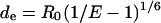 |
(A6) |
and is reported in Table 2.
The Förster distance R0 is defined as:
 |
(A7) |
where n is the refractive index of the medium, QD is the donor quantum yield and κ2 is a geometrical factor. The spectral overlap integral, JDA, is defined as
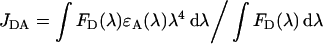 |
(A8) |
where ϵA is the molar absorption coefficient (ϵ) of ALEXA-546 (93000 M−1·cm−1 at 554 nm), FD(λ) is the donor fluorescence emission in the absence of the acceptor at λ=554 nm. Using eqn (A8), we determined JDA=4.810−13 M−1·cm3, assuming n=1.4, κ2=0.476 [26] and QD=0.47 [39].
We obtained, for the pair ALEXA-488/ALEXA-546 and under our experimental conditions, R0=53 Å. This value is very close to that reported in [28,40], which is 50–60 Å for this donor–acceptor pair.
References
- 1.Tenover F. C. Development and spread of bacterial resistance to antimicrobial agents: an overview. Clin. Infect. Dis. 2001;33:S108–S115. doi: 10.1086/321834. [DOI] [PubMed] [Google Scholar]
- 2.Kumana C. R., Ching T. Y., Kong Y., Ma E. C. W., Kou M., Lee R. A., Cheng V. C. C., Chiu S. S., Seto W. H. Curtailing unnecessary vancomycin usage in a hospital with high rates of methicillin resistant Staphylococcus aureus infections. Br. J. Clin. Pharmacol. 2001;52:427–432. doi: 10.1046/j.0306-5251.2001.01455.x. [DOI] [PMC free article] [PubMed] [Google Scholar]
- 3.Astagneau P., Fleury L., Leroy S., Lucet J. C., Golliot F., Regnier B., Brucker G. Cost of antimicrobial treatment for nosocomial infections based on a French prevalence survey. J. Hosp. Infect. 1999;42:303–312. doi: 10.1053/jhin.1998.0612. [DOI] [PubMed] [Google Scholar]
- 4.Menestrina G., Dalla Serra M., Prévost G. Mode of action of beta-barrel pore-forming toxins of the staphylococcal gamma-hemolysin family. Toxicon. 2001;39:1661–1672. doi: 10.1016/s0041-0101(01)00153-2. [DOI] [PubMed] [Google Scholar]
- 5.Prévost G. Toxins in Staphylococcus aureus pathogenesis. In: Thomas P., editor. Microbial Toxins: Molecular and Cellular Biology. Norfolk, U.K.: Horizon Bioscience; 2005. pp. 243–283. [Google Scholar]
- 6.Comai M., Dalla Serra M., Coraiola M., Werner S., Colin D. A., Prévost G., Menestrina G. Protein engineering modulates the transport properties and ion selectivity of the pores formed by staphylococcal gamma-hemolysins in lipid membranes. Mol. Microbiol. 2002;44:1251–1268. doi: 10.1046/j.1365-2958.2002.02943.x. [DOI] [PubMed] [Google Scholar]
- 7.Menestrina G., Dalla Serra M., Comai M., Coraiola M., Viero G., Werner S., Colin D. A., Monteil H., Prévost G. Ion channels and bacterial infection: the case of beta-barrel pore-forming protein toxins of Staphylococcus aureus. FEBS Lett. 2003;552:54–60. doi: 10.1016/s0014-5793(03)00850-0. [DOI] [PubMed] [Google Scholar]
- 8.Miles G., Cheley S., Braha O., Bayley H. The staphylococcal leukocidin bicomponent toxin forms large ionic channels. Biochemistry. 2001;40:8514–8522. doi: 10.1021/bi010454o. [DOI] [PubMed] [Google Scholar]
- 9.Miles G., Movileanu L., Bayley H. Subunit composition of a bicomponent toxin: staphylococcal leukocidin forms an octameric transmembrane pore. Protein Sci. 2002;11:894–902. doi: 10.1110/ps.4360102. [DOI] [PMC free article] [PubMed] [Google Scholar]
- 10.Prévost G., Menestrina G., Colin D. A., Werner S., Bronner S., Dalla Serra M., Baba Moussa L., Coraiola M., Gravet A., Monteil H. Staphylococcal bicomponent leucotoxins, mechanism of action, impact on cells and contribution to virulence. In: Menestrina G., editor. Pore-Forming Peptides and Protein Toxins. London: Taylor and Francis; 2003. pp. 3–26. [Google Scholar]
- 11.Guillet V., Roblin P., Werner S., Coraiola M., Menestrina G., Monteil H., Prévost G., Mourey L. Crystal structure of leucotoxin S component: new insight into the staphylococcal beta-barrel pore-forming toxins. J. Biol. Chem. 2004;279:41028–41037. doi: 10.1074/jbc.M406904200. [DOI] [PubMed] [Google Scholar]
- 12.Mourez M., Kane R. S., Mogridge J., Metallo S., Deschatelets P., Sellman B. R., Whitesides G. M., Collier R. J. Designing a polyvalent inhibitor of anthrax toxin. Nat. Biotechnol. 2001;19:958–961. doi: 10.1038/nbt1001-958. [DOI] [PubMed] [Google Scholar]
- 13.Ferreras M., Hoeper F., Dalla Serra M., Colin D. A., Prévost G., Menestrina G. The interaction of Staphylococcus aureus bi-component gamma hemolysins and leucocidins with cells and model membranes. Biochim. Biophys. Acta. 1998;1414:108–126. doi: 10.1016/s0005-2736(98)00160-6. [DOI] [PubMed] [Google Scholar]
- 14.Meunier O., Ferreras M., Supersac G., Hoeper F., Baba-Moussa L., Monteil H., Colin D. A., Menestrina G., Prévost G. A predicted β-sheet from class S components of staphylococcal gamma-hemolysins is essential for the secondary interaction of the class F component. Biochim. Biophys. Acta. 1997;1326:275–286. doi: 10.1016/s0005-2736(97)00031-x. [DOI] [PubMed] [Google Scholar]
- 15.Sugawara N., Tomita T., Kamio Y. Assembly of Staphylococcus aureus gamma-hemolysin into a pore-forming ring-shaped complex on the surface of human erythrocytes. FEBS Lett. 1997;410:333–337. doi: 10.1016/s0014-5793(97)00618-2. [DOI] [PubMed] [Google Scholar]
- 16.Sugawara-Tomita N., Tomita T., Kamio Y. Stochastic assembly of two-component staphylococcal gamma-hemolysin into heteroheptameric transmembrane pores with alternate subunit arrangements in ratios of 3:4 and 4:3. J. Bacteriol. 2002;184:4747–4756. doi: 10.1128/JB.184.17.4747-4756.2002. [DOI] [PMC free article] [PubMed] [Google Scholar]
- 17.Olson R., Nariya H., Yokota K., Kamio Y., Gouaux J. E. Crystal structure of staphylococcal LukF delineates conformational changes accompanying formation of transmembrane channel. Nat. Struct. Biol. 1999;6:134–140. doi: 10.1038/5821. [DOI] [PubMed] [Google Scholar]
- 18.Pédelacq J. D., Maveyraud L., Prévost G., Baba-Moussa L., Gonzalez A., Courcelle E., Shepard W., Monteil H., Samama J. P., Mourey L. The structure of a Staphylococcus aureus leucocidin component (LukF-PV) reveals the fold of the water-soluble species of a family of transmembrane pore-forming toxins. Structure. 1999;7:277–287. doi: 10.1016/s0969-2126(99)80038-0. [DOI] [PubMed] [Google Scholar]
- 19.Song L., Hobaugh M. R., Shustak C., Cheley S., Bayley H., Gouaux J. E. Structure of staphylococcal alpha-hemolysin, a heptameric transmembrane pore. Science. 1996;274:1859–1866. doi: 10.1126/science.274.5294.1859. [DOI] [PubMed] [Google Scholar]
- 20.Nguyen V. T., Kamio Y., Higuchi H. Single-molecule imaging of cooperative assembly of gamma-hemolysin on erythrocyte membranes. EMBO J. 2003;22:4968–4979. doi: 10.1093/emboj/cdg498. [DOI] [PMC free article] [PubMed] [Google Scholar]
- 21.Baba-Moussa L., Werner S., Colin D. A., Mourey L., Pédelacq J. D., Samama J. P., Sanni A., Monteil H., Prévost G. Discoupling the Ca2+-activation from the pore-forming function of the bi-component Panton-Valentine leucocidin in human PMNs. FEBS Lett. 1999;461:280–286. doi: 10.1016/s0014-5793(99)01453-2. [DOI] [PubMed] [Google Scholar]
- 22.Gravet A., Colin D. A., Keller D., Girardot R., Monteil H., Prévost G. Characterization of a novel structural member, LukE-LukD, of the bi-component staphylococcal leucotoxins family. FEBS Lett. 1998;436:202–208. doi: 10.1016/s0014-5793(98)01130-2. [DOI] [PubMed] [Google Scholar]
- 23.Werner S. Strasbourg, France: University Louis Pasteur; 2001. Structural and functional aspects of the interactions of leucotoxins from Staphylococcus aureus with human leucocytes. Ph.D. Thesis; pp. 1–209. [Google Scholar]
- 24.Alvarez C., Dalla Serra M., Potrich C., Bernhart I., Tejuca M., Martinez D., Pazos I. F., Lanio M. E., Menestrina G. Effects of lipid composition on membrane permeabilization by Sticholysin I and II, two cytolysins of the sea anemone Stichodactyla helianthus. Biophys. J. 2001;80:2761–2774. doi: 10.1016/S0006-3495(01)76244-3. [DOI] [PMC free article] [PubMed] [Google Scholar]
- 25.Tricerri M. A., Behling Agree A. K., Sanchez S. A., Bronski J., Jonas A. Arrangement of apolipoprotein A-I in reconstituted high-density lipoprotein disks: an alternative model based on fluorescence resonance energy transfer experiments. Biochemistry. 2001;40:5065–5074. doi: 10.1021/bi002815q. [DOI] [PubMed] [Google Scholar]
- 26.Lakowicz J. R. Principles of Fluorescence Spectroscopy. New York: Kluwer Academic/Plenum Publishers; 1999. Energy transfer; pp. 368–391. [Google Scholar]
- 27.dos Remedios C. G., Moens P. D. Fluorescence resonance energy transfer spectroscopy is a reliable ‘ruler’ for measuring structural changes in proteins. Dispelling the problem of the unknown orientation factor. J. Struct. Biol. 1995;115:175–185. doi: 10.1006/jsbi.1995.1042. [DOI] [PubMed] [Google Scholar]
- 28.Hong S. H., Maret W. A fluorescence resonance energy transfer sensor for the beta-domain of metallothionein. Proc. Natl. Acad. Sci. U.S.A. 2003;100:2255–2260. doi: 10.1073/pnas.0438005100. [DOI] [PMC free article] [PubMed] [Google Scholar]
- 29.Yegneswaran S., Wood G. M., Esmon C. T., Johnson A. E. Protein S alters the active site location of activated protein C above the membrane surface. A fluorescence resonance energy transfer study of topography. J. Biol. Chem. 1997;272:25013–25021. doi: 10.1074/jbc.272.40.25013. [DOI] [PubMed] [Google Scholar]
- 30.Wu P., Brand L. Orientation factor in steady-state and time-resolved resonance energy transfer measurements. Biochemistry. 1992;31:7939–7947. doi: 10.1021/bi00149a027. [DOI] [PubMed] [Google Scholar]
- 31.Sugawara N., Tomita T., Sato T., Kamio Y. Assembly of Staphylococcus aureus leukocidin into a pore-forming ring-shaped oligomer on human polymorphonuclear leukocytes and rabbit erythrocytes. Biosci. Biotechnol. Biochem. 1999;63:884–891. doi: 10.1271/bbb.63.884. [DOI] [PubMed] [Google Scholar]
- 32.Malghani M. S., Fang Y., Cheley S., Bayley H., Yang J. Heptameric structures of two alpha-hemolysin mutants imaged with in situ atomic force microscopy. Microsc. Res. Tech. 1999;44:353–356. doi: 10.1002/(SICI)1097-0029(19990301)44:5<353::AID-JEMT6>3.0.CO;2-0. [DOI] [PubMed] [Google Scholar]
- 33.Czajkowsky D. M., Sheng S. T., Shao Z. F. Staphylococcal alpha-hemolysin can form hexamers in phospholipid bilayers. J. Mol. Biol. 1998;276:325–330. doi: 10.1006/jmbi.1997.1535. [DOI] [PubMed] [Google Scholar]
- 34.Cheung H. C. Resonance Energy Transfer. In: Lakowicz J. R. Principles, editor. Topics in Fluorescence Spectroscopy. New York: Plenum Press; 1991. pp. 127–176. [Google Scholar]
- 35.Parente R. A., Nir S., Szoka F. C., Jr Mechanism of leakage of phospholipid vesicle contents induced by the peptide GALA. Biochemistry. 1990;29:8720–8728. doi: 10.1021/bi00489a031. [DOI] [PubMed] [Google Scholar]
- 36.Rapaport D., Peled R., Nir S., Shai Y. Reversible surface aggregation in pore formation by pardaxin. Biophys. J. 1996;70:2502–2512. doi: 10.1016/S0006-3495(96)79822-3. [DOI] [PMC free article] [PubMed] [Google Scholar]
- 37.Anzlovar S., Dalla Serra M., Dermastia M., Menestrina G. Membrane permeabilizing activity of linusitin from flax seed. Mol. Plant-Microbe Interact. 1998;11:610–617. [Google Scholar]
- 38.Scaloni A., Dalla Serra M., Amodeo P., Mannina L., Vitale R. M., Segre A. L., Cruciani O., Lodovichetti F., Greco M. L., Fiore A., et al. Structure, conformation and biological activity of a novel lipodepsipeptide from Pseudomonas corrugata: cormycin A. Biochem. J. 2004;384:25–36. doi: 10.1042/BJ20040422. [DOI] [PMC free article] [PubMed] [Google Scholar]
- 39.Panchuk-Voloshina N., Haugland R., Bishop-Stewart J., Bhalgat M., Millard P., Mao F., Leung W., Haugland R. Alexa dyes, a series of new fluorescent dyes that yield exceptionally bright, photostable conjugates. J. Histochem. Cytochem. 1999;47:1179–1188. doi: 10.1177/002215549904700910. [DOI] [PubMed] [Google Scholar]
- 40.Gohlke C., Murchie A. I., Lilley D. M., Clegg R. M. Kinking of DNA and RNA helices by bulged nucleotides observed by fluorescence resonance energy transfer. Proc. Natl. Acad. Sci. U.S.A. 1994;91:11660–11664. doi: 10.1073/pnas.91.24.11660. [DOI] [PMC free article] [PubMed] [Google Scholar]