Abstract
We report substantially improved performance of high-power quantum cascade lasers (QCLs) by using epitaxial-side-down mounting that provides superior heat dissipation properties. We used aluminum nitride as the heatsink material and gold–tin eutectic solder. We have obtained continuous wave power output of 450 mW at 20°C from mid-IR QCLs. The improved thermal management achieved with epitaxial-side-down mounting combined with a highly manufacturable and scalable assembly process should permit incorporation of mid-IR QCLs in reliable instrumentation.
Keywords: continuous wave operation, room temperature operation, high-power lasers, mid-IR semiconductor lasers
Conceived in the early 1970s (1, 2) and first demonstrated in 1994 (3), quantum cascade lasers (QCL) are emerging mid- to far-IR light sources with critical applications including spectroscopy, medical and environmental sensing, and national security. Significant progress has been made in recent years in improving device performance, mostly through increased sophistication of the internal structure of QCLs and because of advances in epitaxial growth and device processing technologies. As a result, continuous wave (CW) operation of QCLs at room temperature (RT) has been demonstrated at several mid-IR wavelengths (4–6). Yet, significant obstacles remain on the path to incorporating QCLs into real-world instruments in systems.
The first of such obstacles is the rather high “admission barrier” to using QCLs outside of a laboratory bench. Because of the relative youth of this technology, the few commercial QCL offerings available today have not yet achieved the plug-and-play level of ease of use typical of modern telecom laser diodes.
Next, it is well understood that today’s commercial QCL assemblies cannot be economically mass-fabricated, making them unattractive to system manufacturers concerned with potential volume production. The main technical reason for this problem is the fact that, currently, QCL assemblies are built by using materials and techniques unsuitable for scaling up to industrial production levels. Driven by the need to maintain acceptable yield during manual assembly that is justified by the present market size, current techniques emphasize ease of use at the expense of manufacturability, scalability, and long-term reliability. Therefore, there is no clear pathway from today’s low volume QCL production to large-scale industrial manufacturing necessary for the widespread acceptance of QCL devices.
Finally, those same assembly choices necessarily sacrifice thermal performance of the finished QCL assembly, thus preventing the realization of the full performance potential built into the QCL chips themselves.
Below, we will explain the reasons for the current state of affairs and describe the initial results of our attempts to develop a mounting technology for QCLs that will unlock their performance potential, while at the same time allowing eventual high-volume production of QCL-based IR light sources viable for real-world applications.
Ex-Chip Thermal Management and Material Selection for Performance and Manufacturability
Given the recent advances in laser design, structure growth, and device processing, ex-chip thermal management has become one of the more important performance-limiting factors for high-temperature, high-power CW operation of QCLs. Compared with other classes of semiconductor lasers, QCLs suffer from an especially unfortunate convergence of physical properties that makes thermal management particularly critical. On one hand, today’s QCLs possess low electro-optical power conversion efficiencies, on the order of single-digit percent. On the other hand, QCLs exhibit high series resistance: devices requiring >10 V of bias at hundreds of milliamperes of drive current are typical. Considered together, these two facts mean that ≈10 W of heat is generated inside the QCL chip during CW operation. Although there are important design solutions inside the chip itself that enhance heat removal from the active zone (such as, for example, the use of buried heterostructure design), this heat ultimately must be dissipated by the thermal management system external to the laser chip. Given the strong dependence of QCL characteristics on device temperature, the importance of thermal management for QCL performance becomes apparent.
The first level of thermal management outside of the QCL chip itself is how the laser device is attached to its heatsink. The traditional and most commonly used way to mount QCLs has been in the epitaxial-side-up (epi-up) geometry. Epi-up is the safe choice for manual laser device mounting. First, the active zone of a QCL resides in the epitaxial structure itself and is thus only a few micrometers below the top (epitaxial) surface of the chip. At the same time, the bottom side of the chip, the back side of the blank semiconductor wafer on which the laser is grown, is typically at least 100 μm away. Therefore, in the epi-up geometry the active zone of the laser is far removed from the molten pool of hand-applied solder on the substrate. Large variations of solder thickness can be tolerated without the risk of sinking the laser facets or exposed device sides into the solder, causing beam shadowing at best and complete device shorting at worst (7). The problem of shorting on the sides of the laser device can be eliminated by using solder islands narrower than the laser, but with the typical QCLs being <500 μm wide, such precise solder shape control is virtually impossible to exercise by hand.
Next, the epi-up geometry much relaxes the requirements on both the geometric tolerances of the heatsink and on the precision of laser placement. It is obvious that the heatsink must not be shorter than the laser cavity, because in such a case heat removal from laser regions overhanging the heatsink will be extremely inefficient. The obvious solution is to lengthen the heatsink until one can be assured of placing the laser device by hand with no overhang on either side. However, as is the case for most other in-plane semiconductor lasers, the emission pattern of QCLs is highly divergent (tens of degrees perpendicular to the epitaxial planes). Therefore, if the heatsink length is significantly larger than the length of the laser cavity, the beam may start clipping the heatsink’s surface, making downstream light collection difficult. From the simplest geometric optics considerations, it is obvious that the epi-up geometry (≈100 μm from the emitting aperture to the heatsink surface) is much more tolerant of laser/submount length mismatch than the epitaxial-side-down (epi-down) geometry (only a few micrometers from the aperture to the heatsink). Further, from the same logic, laser-positioning tolerances on the heatsink are much relaxed in the epi-up geometry.
However, from the thermal performance standpoint, the epi-up geometry is undesirable. It introduces a layer of low thermal conductivity (InP, 70 W/mK at RT) between the active zone and the heatsink that is ≈2 orders of magnitude thicker than in the case of the epi-down geometry, thus increasing the thermal resistance between the active zone and the heatsink and consequently dramatically increasing active zone temperature in the epi-up geometry for the same heatsink temperature.
On the materials side, lasers are typically soldered to heatsinks made of copper (Cu) using pure indium (In) as solder and an appropriate flux. Cu is the obvious choice because of its high thermal conductivity of 393 W/mK at RT, good machinability, and easy availability. In offers the advantages of a low melting point (157°C), ductility even at cryogenic temperatures (thus facilitating low temperature testing), and the ease with which it can be used by hand, without the use of any specialized equipment.
However, this approach entails several problems, from the standpoints of both performance and manufacturability. Performance-wise, the coefficient of thermal expansion (CTE) of Cu (17 × 10−6 K−1) represents a large mismatch to the CTE of typical III–V semiconductor materials (InP, 4.5 × 10⁻⁶ K−1; GaAs, 5.9 × 10⁻⁶ K−1). Such a large mismatch creates undesirable stresses in the laser structure, both those frozen in after soldering and those occurring because of normal operational temperature gradients. These stresses significantly decrease device lifetime and in extreme cases lead to immediate failure. Other traditional high-performance heatsink materials suffer from the same problem, notably diamond (2.3 × 10⁻⁶ K−1). Next, In solder migration and whisker formation has been shown to lead to long-term device degradation or catastrophic failure (8). Finally, the use of flux is undesirable in high-reliability, hermetic optoelectronic packages.
From the manufacturability standpoint, In (because of its rapid oxidation rate) is not compatible with flux-free soldering without aggressive preprocessing, usually an acid etch immediately before use. Even if flux is used, In oxidation often leads to unsatisfactory soldering results, and oxide removal is still advisable in this case. In practice, this finding means that parts using In solder (irrespective of base material) have to either be fabricated individually or in very small batches and used up shortly after fabrication or processed immediately before use to etch away the formed oxide. This limitation places a significant additional burden on economical volume production that is predicated on parallel processing of parts and the possibility of long-term storage. Further, In is not particularly well suited for economical direct deposition on heatsink substrates using standard industrial microfabrication techniques. On the other hand, with manual application of solder it is difficult to precisely control solder shape and particularly thickness, both negative characteristics, as shown above. The widely accepted conclusion is that mounting of semiconductor lasers on Cu heatsinks using In solder and flux is a nonscalable process with low reproducibility and reduced device reliability.
The thermal advantages of epi-down mounting of high-power semiconductor lasers have been extensively exploited in the near-IR region (9). There exist reports of early attempts at epi-down mounting of QCLs on Cu using In solder (7, 10) and on diamond using unspecified solder (4). However, overall there is an absence of a systematic exploration of the advantages of epi-down mounting geometry for high-power mid- and long-IR QCLs, and we know of no reports offering an epi-down mounting process that could be used to mass-produce high-reliability QCL devices suitable for industrial use.
We accomplished fluxless attachment, avoiding In as the solder, through employing the widely used gold–tin (AuSn) eutectic solder system (11). Because the eutectic composition of the AuSn alloy is 80% Au/20% Sn, this material system has the advantage of low oxidation rate and thus permits fluxless soldering, as well as long-term storage without the need to process the solder in any way before reflow. Further, in marked contrast to In, AuSn is highly compatible with standard microfabrication techniques, allowing formation of precisely defined solder shapes with well controlled thickness directly on the surface of the submount material. This approach minimizes problems caused by excessive solder described above and is a critical step in allowing high-reliability, reproducible epi-down mounting of semiconductor lasers.
However, being a hard solder with a high melting point (280°C), AuSn places stringent demands on the CTE match between the laser and the submount material. When the solder solidifies after die attach, it freezes the die to the submount. As the assembly is cooled form the solder’s solidus point to RT, different CTE of the die and the submount introduce undesirable stresses into the laser structure. This effect is the more severe the harder the solder and the higher the temperature difference between the solder’s solidus point and RT. The only way to mitigate this problem for a given device–solder combination is to use a submount material whose CTE is closely matched to that of the device material, which automatically rules out the use of Cu or diamond.
With this point in mind, we selected AlN as the submount material. AlN has been widely used for p-side down mounting of near-IR high-power diode lasers (9). AlN has several advantages over other possible submount material choices. First, its CTE (4.5 × 10⁻⁶ K−1) is perfectly matched to that of InP. This quality minimizes undesirable stresses on the laser structure, both those frozen-in after die mounting and those arising from thermal cycling during device operation. Second, high-grade AlN exhibits high thermal conductivity of 230 W/mK at RT. Although not as high as that of Cu, this value is 3 times higher than thermal conductivity of InP (70 W/mK at RT), which naturally enhances heat transfer from the laser’s active zone into the heatsink by reducing thermal resistance in the epi-down vs. epi-up geometry. Finally, AlN is an electrical insulator, and hence it permits easy formation of electrical interconnects on the submount for incorporating various passive monitoring elements into the integrated chip on carrier (CoC) assembly.
Therefore, the AlN/AuSn system simultaneously ensures high thermal performance of epi-down mounted semiconductor lasers and offers the benefits of highly scalable, manufacturing-level fabrication. It holds promise to eventually enable economical mass production of high-performance and high-reliability QCL devices that fully realize the performance potential of QCL chips.
Device Fabrication
The laser submounts used in this study were fabricated from polished AlN substrates, 250-μm thick. Standard thin-film technology was used to blanket both sides of the submounts with Ti/Pt/Au metallization and to pattern the top metallization to provide electrical interconnects. Finally, a stripe of AuSn was vacuum-deposited on the top side of the submounts. It should be emphasized that the submounts were fabricated by using wafer-level processes, and final submounts were diced from the completed wafer. Thus, the fabrication of our submounts readily yields itself to volume production.
The QCLs were grown and processed in a manner similar to that described in ref. 5, with the exception of the regrowth step. The design wavelength was ≈5.26 μm at RT. The wafers were processed into ridge waveguide structures, cleaved into laser bars and then into individual laser chips, yielding Fabry–Perot devices with the nominal cavity length of 3 mm. The emitter width was ≈12 μm. The laser facets were not coated. Particularly, note that all of the QLC devices studied in this work did have the thick (≈5 μm) layer of electroplated Au on the epi-side electrical contact.
QCL chips were soldered to submounts by using a high-precision manual die bonder in the epi-down geometry. For comparison, epi-up assemblies also were fabricated. A thermistor was soldered to the submount in a close proximity (≈0.5 mm) of the laser by using a PbIn solder with process temperature below that of AuSn. Unless otherwise specified in the text, all device temperatures quoted below were measured by these integrated thermistors. The chip-on-carrier assemblies were wire-bonded and mounted on small Cu heat spreaders by using In solder. The heat spreaders contained electrical interconnects as well as provisions for attachment to our test equipment.
Device Testing Results
The complete QCL assemblies (chip-on-carrier on heat spreader) were initially mounted on a large, water-cooled heatsink by using thermal grease for reduced thermal resistance. L-I-V curves were recorded at constant heatsink temperature. In later studies, QCL assemblies were mounted onto appropriately sized thermoelectric coolers (TEC), and the thermistor integrated on the submount was used as the feedback element for temperature control. Uncollimated laser output was measured by using a large area calibrated thermopile detector positioned close to the laser facet. Because our devices lacked facet coatings, they emitted light equally in both directions. Thus, the optical power results shown below represent actual detector readings multiplied by a factor of 2.
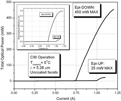
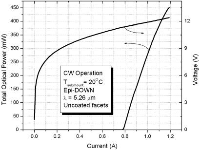
Fig. 1 shows CW results of identical 3-mm-long QCLs with l to ≈5.26 μm mounted epi-down and epi-up for Theatsink = 0°C. The epi-down geometry led to dramatic performance gains, most notably to up to 15-fold increase in maximum optical power, from 25 mW epi-up to 450 mW epi-down. Maximum wallplug efficiency rose from 0.25% to 3% for epi-down devices. Threshold current density fell 25%, from 2.82 to 2.11 kA/cm2, and slope efficiency rose from 530 to 1,340 mW/A. The Theatsink = 0°C was necessitated by the fact that the epi-up device did not lase at RT because of the high mirror losses of uncoated laser facets. Not surprisingly, the epi-down devices performed well at RT, producing 450-mW CW at Tsubmount = 20°C under active thermoelectric temperature control (Fig. 2). Note that although in this experiment the temperature of the water-cooled heatsink at the “hot” (heat rejection) side of the TE cooler had to be maintained at −3°C; this requirement reflects the limitation of the particular TE cooler used and is in no way relevant to the performance of the actual QCL device.
Fig. 1.
Light vs. current and wallplug efficiency results for CW operation of 5.26-mm QCLs with uncoated facets mounted epi-up and epi-down on AlN submounts with passive cooling on a water-cooled heatsink (Theatsink = 0°C). (Inset) Electrooptical conversion efficiency for the same devices.
Fig. 2.
Light vs. current and operating voltage for CW operation of a 5.26-mm QCL with uncoated facets mounted epi-down on an AlN submount, with active TEC cooling to maintain Tsubmount = 20°C.
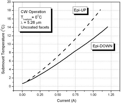
Fig. 3 shows submount temperature measured by integrated thermistors located on the laser submount. In high-drive current regime, the overheating penalty of the epi-up as compared with the epi-down geometry is >5°C at submount level. This result means that the active zone overheating penalty is higher still for epi-up devices, which explains the dramatic performance gains achieved using the epi-down geometry. The limitations of our test equipment (CW current only; minimum heatsink temperature of −5°C) have so far prevented us from quantifying active zone overheating and calculating the thermal resistance for epi-down and epi-up geometries.
Fig. 3.
Submount temperature rise vs. drive current for CW operation of 5.26-mm QCLs with uncoated facets mounted epi-up and epi-down on AlN submounts, with passive cooling on a water-cooled heatsink (Theatsink = 0°C).
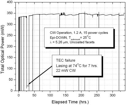
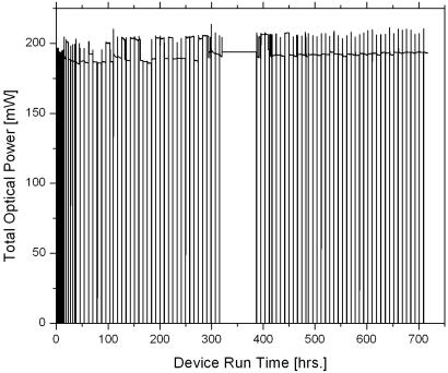
One of the promises of QCL mounting on AlN submounts with AuSn solder, as compared with In mounting on Cu, is increased device reliability. Fig. 4 shows preliminary lifetime data for one of the 5.26-μm devices. The device was intentionally power-cycled numerous times during the test, because this cycling increases stress and tends to promote device failure. The device did not show any measurable performance degradation over the test period of >300 h. It is worth noting that at ≈25 h into the test, the TEC failed, and the device operated at the temperature of 74°C for nearly 7 h without any noticeable change in the device performance when the TEC function was restored. Finally, note that during the first ≈50 h of device operation, the total optical power increased, which was accompanied by a decrease in threshold current. This burn-in effect needs further investigation. Lifetime data for a similar QCL device with a 6.39-μm design wavelength are shown in Fig. 5. As of this writing, this device surpassed 700 h of operation. Overall, the 10 epi-down QCL assemblies fabricated for this study (with lasers of varying wavelengths between 5 and 8 μm) have accumulated close to 4,000 h of operation at maximum rated current in CW regime at RT, all with no observable performance degradation and no failures attributable to the laser assembly. The average run time in this group is ≈400 h, with the minimum of >100 h and the maximum of >700 h. These results provide an encouraging early indication that the random failure rate for QCL devices assembled by using our technology is reasonably low and that we have not yet reached the wear-out failure regime after hundreds of hours of high-power operation.
Fig. 4.
Lifetime data for CW operation of a 5.26-mm QCL with uncoated facets (drive current = 1.2 A), mounted epi-down on an AlN submount at Tsubmount = 25°C. During the test the device was subjected to 15 power cycles. Periodic power variations are due to ambient temperature changes affecting the laser.
Fig. 5.
Lifetime data for CW operation of a 6.39-mm QCL with uncoated facets and thick electroplated Au on the epi-side contact, mounted epi-down on an AlN submount. Conditions were as follows: drive current, 1.25 A CW; Tsubmount = 25°C; active TEC temperature control; nitrogen-rich air; intentional power cycling. Power variations are due to optical mode switching; however, average power in either of the modes does not degrade with run time. At t≈320 h, the data collection system failure led to the loss of data for ≈60 h. The laser, however, continued to function throughout.
Conclusions
In conclusion, we have developed a highly manufacturable and scalable process for epi-down mounting of QCLs on aluminum nitride submounts using fluxless attachment with AuSn eutectic solder. As expected, QCLs mounted in this manner showed dramatic performance improvements over identical laser chips mounted epi-up. Further, QCL devices so mounted exhibit no measurable degradation after hundreds of hours of high-power operation. This combination of improved device performance and volume production-compatible nature of our mounting process charts the pathway for the fabrication of QCL assemblies suitable for system-level integration in reliable commercial instrumentation.
Acknowledgments
This work was supported in part by Defense Advanced Research Projects Agency Contract HR0011-C-0102.
Abbreviations
- CTE
coefficient of thermal expansion
- CW
continuous wave
- epi-down
epitaxial-side-down
- epi-up
epitaxial-side-up
- QCL
quantum cascade laser
- RT
room temperature
- TEC
thermoelectric cooler.
Footnotes
Conflict of interest statement: No conflicts declared.
References
- 1.Esaki L., Tsu R. IBM J. Res. Dev. 1970;14:61–65. [Google Scholar]
- 2.Kazarinov R., Suris R. Sov. Phys. Semicond. 1971;5:707–709. [Google Scholar]
- 3.Faist J., Capasso F., Sivco D., Sirtori C., Hutchinson A., Cho A. Science. 1994;264:553–556. doi: 10.1126/science.264.5158.553. [DOI] [PubMed] [Google Scholar]
- 4.Beck M., Hofstetter D., Aellen T., Faist J., Oesterle U., Ilegems M., Gini E., Melchior H. Science. 2002;295:301–305. doi: 10.1126/science.1066408. [DOI] [PubMed] [Google Scholar]
- 5.Evans A., Yu J., David J., Doris L., Mi K., Slivken S., Razeghi M. Appl. Phys. Lett. 2004;84:314–316. [Google Scholar]
- 6.Evans A., Yu J., Slivken S., Razeghi M. Appl. Phys. Lett. 2004;85:2166–2168. [Google Scholar]
- 7.Gmachl C., Sergent A. M., Tredicucci A., Capasso F., Hutchinson A., Sivco D., Baillargeon J., Chu S., Cho A. IEEE Photonics Tech. Lett. 1999;11:1369–1371. [Google Scholar]
- 8.Mizuishi K. J. Appl. Phys. 1984;55:289–295. [Google Scholar]
- 9.Liu X., Hu M., Nguyen H., Caneau C., Rasmussen M., Davis R., Zah C.-E. IEEE Trans. Adv. Packaging. 2004;27:640–646. [Google Scholar]
- 10.Hofstetter D., Beck M., Aellen T., Faist J., Oesterle U., Ilegems M., Gini E., Melchior H. Appl. Phys. Lett. 2001;78:1964–1966. [Google Scholar]
- 11.Weiss S., Bader V., Azdasht G., Kasulke P., Zakel E., Reichl H. Proceedings of the 47th Electronic Components and Technology Conference, San Jose, CA, May, 1997; Piscataway, NJ: Inst. Electrical Electronics Engineers; 1997. pp. 780–787. [Google Scholar]


