

Abstract
Image enhancement has been shown to improve the perceived quality of images and videos for people with visual impairments. The MPEG coding scheme makes spatial filtering, likely to help those with such impairments, possible at the decoding stage. We implemented a real-time platform for testing and improving contrast enhancement algorithms for MPEG video, with controls appropriate for the target population. The necessary additional processing runs efficiently on a general-purpose PC and can be integrated easily into existing MPEG-2 decoders. The system has enabled us to substantially improve the previous filtering algorithm; reducing artifacts exhibited in the previous implementation and should facilitate individual user-selection of enhancement parameters in evaluation studies.
Keywords: Video, Television, Vision Rehabilitation, Image enhancement, Visual impairment, Adaptation, Artifact, Quantization, DCT Filtering
1. Objectives and background
Many otherwise healthy people suffer from a variety of visual impairments. Eye diseases are more common at older ages and thus the prevalence of vision impairment is growing and is expected to increase with the aging of the population. Television plays a large role in the lives of most people in today’s society, not excluding those with such visual impairments. This population watch TV for comparable lengths of time and at similar frequencies to those whose vision is not impaired1, yet they are severely disadvantaged from fully enjoying the medium. Our goal is to develop image-enhancement techniques applicable to video to assist people with visual impairments, particularly those due to central retinal vision loss.
1.1 Image Enhancement
People with visual impairments due to central vision loss commonly experience a decrease in contrast sensitivity at high spatial frequencies. Image enhancement to compensate for these losses was first proposed by Peli & Peli in 19842. The value of this approach when applied to both still and moving image information has been demonstrated in a number of studies using various techniques3–5. The most flexible of these was the series of DigiVision® devices, which provided an implementation of the adaptive enhancement algorithm6 in real time7. In their device the analog video signal was separated into luminance (brightness) and chrominance (color) components, and the enhancement was then applied to the luminance component only (the color component was not modified). A device that provided color correction (to correct color distortions introduced by modifying the luminance component) was developed for a later study3. An example of a video frame enhanced using the device is shown in Fig. 1.
Fig. 1.
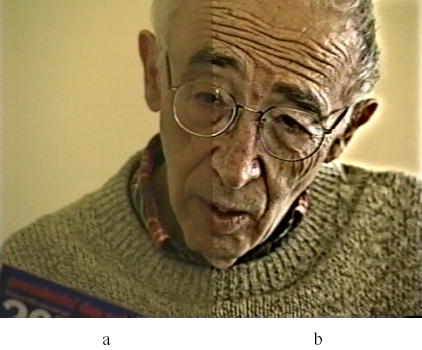
Digivision® implementation7 of the adaptive enhancement algorithm6, used in a previous study3. (a) Section of unenhanced frame. (b) Section of enhanced frame. Image taken from “Hope in Sight”, an educational and motivational video for patients with age-related macular degeneration (AMD) and their caretakers, developed by the New England Research Institute. The video was produced with the enhancement shown at b.
1.2 MPEG Video Coding
MPEG-2 is an international standard8 used for the encoding and decoding of video information. In order to reduce the data transmitted in systems with limited bandwidth (e.g. cable) or to reduce the storage requirements for video media (e.g. DVD), MPEG takes advantage of statistical redundancies (spatial and temporal) in video signals. MPEG-2 is neither the most complex nor the most efficient system for achieving these goals (due in part to the computational limitations of processors at the time the standard was developed), but it is the coding standard used in most of today’s digital television-based media.
MPEG encodes a stream of pictures, each of which is either an entire video frame or a field from an interlaced video frame. Each picture is broken into luminance and chrominance blocks (8×8 arrays of pixels), which are then processed by the block encoder. Luminance blocks are grouped into 2×2 sets, to give 16×16 pixel macroblocks. Each macroblock also contains a number of chrominance blocks (2, 4 or 8 depending on the chrominance resolution chosen).
A Group-of-Pictures (GOP) size and sequence is specified such that periodically an entire picture will be encoded completely using the JPEG coding scheme (Discrete Cosine Transform (DCT) and quantization, below). Such pictures are known as intra-pictures, and the blocks that form them intra-blocks. All other pictures are made up from a mixture of these and inter blocks. These are encoded using prediction methods that encode only the difference between the macroblock and some reference macroblock in a previous or future picture. Inter-pictures are formed from inter-blocks when a search for a sufficiently matching macroblock from surrounding pictures succeeds. When this fails, new intra-blocks are generated instead. The regular occurrence of an intra-picture allows decoding to commence quickly beginning part way through a stream (for example when selecting a digital TV channel), or recovering from lost references due to pictures lost during transmission. They also prevent coding errors from accumulating.
Both intra- and inter-blocks are transformed using a two dimensional DCT, which is a completely equivalent (lossless) representation of the block. The dc (mean luminance) level and low spatial frequencies dominate in most image content, so this transformation results in the compaction of most of the energy into just a few of the elements of the block.
Transformed blocks are quantized using 8×8 quantization matrices (Fig. 2). During this process, each coefficient in the DCT transformed block is divided by the corresponding value in the intra or inter quantization matrix (pointwise division). The results are then integer rounded (an irreversible, lossy operation). The quantization matrix is designed such that those elements containing information deemed less perceptually significant (in the higher spatial frequency area) are quantized more coarsely. The quantization step converts many low value DCT coefficients to zero. Subsequently, a lossless encoding step ensures that the “runs of zeroes” resulting from this quantization are efficiently stored or transmitted. An encoder may specify the quantization matrices to be used, or may choose to use default matrices (Fig. 2).
Fig. 2.
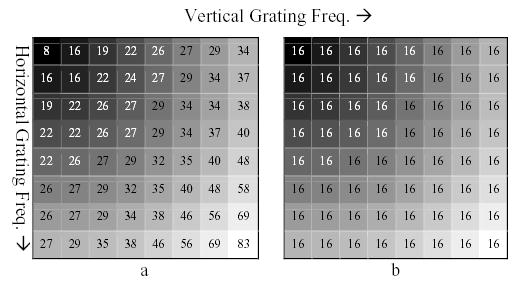
(a) Default Quantization matrix for intra-blocks. Values closest to the upper-left corner are quantized the least as most of the significant information in the DCT transformed block is located here. Values closest to the lower-right corner are quantized more harshly. Bands of increasing spatial frequency from upper-left to lower-right are illustrated as a black to white gradient. (b) The MPEG standard defines a default 8×8 matrix for inter-blocks whose values have a uniform value (16). The difference or error coded by these inter blocks does not have the same spatial frequency spectrum commonly found in natural images.
During decoding, the reverse of these processes is carried out on the MPEG stream. The same quantization matrices are used to dequantize the transformed blocks. An inverse-DCT is then performed to provide the decoded pixel values. Predicted block differences are decoded and then combined with their reference block counterparts, and complete pictures are returned for display. Due to the integer rounding used during encoding, the returned picture will never exactly match that presented to the encoder, instead a close approximation will result. Ideally, the differences will be barely perceptual for a person with normal sight observing the display from a standard observation distance. However, conventional image enhancement (Section 1.1) can make some of these differences (in particular, ‘block’ artifacts) more visible, in addition to the desired enhancement of decoded image information9.
1.3 MPEG Video Enhancement
Coefficients in a DCT transformed block correspond to weights of different spatial frequency in the DCT domain, with increasing spatial frequency starting from the dc component at position (1,1) (top left) and moving towards the lower right corner. This relationship is further illustrated in Figs. 2 and 3. Performing contrast enhancement filtering within each MPEG block can be easily achieved by increasing the value of specific coefficients in the 8×8 quantization matrix (used for decoding) corresponding to the spatial frequencies we wish to enhance9, 10. By introducing this difference between the quantization matrices used for encoding and decoding, we effectively amplify specific spatial frequencies. Such an operation has the advantage of being internal to the block, avoiding those block artifacts that result from post-decoding-enhancement of coded content9.
Fig. 3.
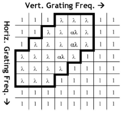
The band enhancing filter matrix applied in the previous study10. Values within the lined area correspond to the locations of frequencies to be enhanced using a variable λ and approximate four curved bands of spatial frequency (ranging from 2.8 to 6.8 cycles/degree within the constraints given in Section 1.3). These frequencies were chosen to match the range of frequencies that require higher contrasts to be seen by those with visual impairments due to disease of the central retina. Three of the coefficients are multiplied by an additional value, α. This introduced an asymmetry to the enhancement. This was done to emphasize vertical edge enhancement relative to horizontal edges in an effort to reduce interlacing artifacts. Values of α=1.5 and 1 ≤ λ ≤ 5 were used in the previous study10.
When enhancing images and video for people with visual impairments, we seek to increase the contrast of spatial frequencies to which the viewer is sensitive only at high contrast4. A band limited filter was used as there is no advantage in enhancing information at spatial frequencies that the viewer is already sensitive to at most levels, nor is there any need to amplify high spatial frequencies that are not detectable at any achievable contrast (although their manipulation might be beneficial to the general appearance of the image as we show below). There is also a limitation on the enhancement of the very low frequencies within the block as this can cause block artifacts. Although the effect of a given filter on image spatial frequencies (in terms of cycles per image) is well defined, for television viewers, retinal spatial frequencies are affected also by the screen size and seating distance. For example, many patients with visual impairment sit closer to the television than those who are normally sighted1, thereby shifting the retinal spatial frequency content to lower bands. We use a 27″ television screen for image enhancement experiments. In a previous study11, patients with age related macular degeneration (AMD) reported that they usually sat between 2′ to 4.5′ from the television at home.
When designing the previous MPEG enhancement algorithm, a TV size of 27″ and a seating distance of 36″ were assumed10. The algorithm sought to enhance frequencies in the range below 8 cycles/deg (band-limited enhancement). Within these conditions NTSC video (having a resolution of 720×480 pixels) contains about 22 pixels/deg horizontally. An MPEG block (having a resolution of 8×8 pixels) occupies about 0.37 degrees of visual field, and represents a range of spatial frequencies from 0 to 9.6 cycles/deg10, in the horizontal direction.
Based on these calculations, the filter modified only certain matrix values (Fig. 3), corresponding to spatial frequencies below the cut-off point of 8 cycles/deg. The modifying filter was designed with two variables; λ controlled the degree of enhancement and α was held constant at 1.5. The slight asymmetry affected by the placement of this parameter was introduced into the filter to reduce interlacing artifacts (by increasing vertical edge enhancement relative to horizontal edges). The filtering is explained further and illustrated in Fig. 3. Intra and inter matrices were modified in the previous study by processing short MPEG video segments offline using Restream12 software to replace the encoded quantization matrices with the enhancement modified versions. These were used to provide different enhancement levels of the same video segment. It was found that levels of enhancement up to λ=4.0 were preferred in video with little motion10.
1.4 Aims
It was argued10 that this technique was appropriate for real-time implementation because of its low computational complexity. As the implementation technique requires modification only to the decoder, it should be compatible with all existing MPEG compressed content.
Our first objective was to achieve a real-time implementation of the enhancement used in the previous study10. This required that every MPEG picture have each of its constituent luminance blocks processed by the filtering algorithm during the normal de-quantization step, with sufficiently low overhead that each frame would be decoded in time to display on-screen at the correct frame rate. The second objective was to use this new real-time capability as a tool to visually investigate the effects of variations of the algorithm and of the parameters used10.
We present this successful implementation and show that the method is valid for any MPEG-2 source. Also, we illustrate how this new application is enabling further research into post-transmission compressed-domain contrast enhancement techniques, yielding improved filtering and facilitating the development of solutions for a number of problems encountered in previous efforts.
2. Implementation
We investigated a number of potential platforms on which to implement the system. Modifying an MPEG-2 decoding circuit inside an existing DVD player or TV set-top box would have been a solution. However, this would have not readily transferred to other decoding systems and would have been technically challenging without adequate documentation.
Video decoding on a Digital Signal Processor (DSP) is an expanding field of technology. Many commercial MPEG-2 decoders now use such devices in their implementations. We investigated the possibility of working with a developer and distributor of these solutions, but so far have been unable to find a partner willing to allow us (a small third party) examine or modify their decoder implementations.
We chose to modify open-source software that is available to decode MPEG-2 streams on standard PC platforms. The software library, libmpeg213 is written in the C programming language. The software is licensed under the GNU General Public License14, which allowed us full access to examine the code relevant to our work. Many DSPs also have C-compilers available, so by pursuing this route we were not ruling out the future use of the DSP option. A DSP solution would facilitate integration of our enhancement into DVD and digital TV systems as a separate menu option.
2.1 Decoder modification
We modified the MPEG decoding library code to perform the pointwise multiplication of the quantization matrix by a filter matrix (Fig. 3) whilst dequantizing luminance blocks. This modification allowed a real-time implementation of the previous algorithm, as well as the ability to test other filtering approaches. We confirmed that any out-of-range values generated by the multiplication are clipped by existing code in the decoder. In addition, we made modifications so that this multiplication could be performed only on a defined portion of the picture. All enhancement parameter values (set with a graphical user interface) are read from memory at regular intervals, allowing real-time adjustment of the filtering while the video is presented on the display.
2.2 Decoder Control
The filter matrix and other parameters are set by a separate user interface computer program, developed to meet the second objective outlined above. The interface can be used as a simple real-time controller for the implementation of the previous method, a matrix/element level editing interface for research purposes, or a mixture of both. Also, we have interfaced a simple large-button remote control (designed for those with visual impairments, many of whom are elderly) to the decoder interface that adjusts the enhancement-value. We used it during development to control the enhancement from a distance (for example, when examining a television screen output closely, away from the computer), and to allow patients to adjust the enhancement and provide feedback during development. Patients in future evaluation studies will use the remote control to select the level of enhancement they prefer.
2.2.1 Matrix-level and Element-level control
In our implementation, the intra and inter quantization matrices can be adjusted together or separately. Previously10, artifacts appeared in sequences exhibiting fast motion. These artifacts were associated with the application of identical filter matrices to both inter and intra quantization matrices. There also was a noticeable difference in the enhancement effect on intra-pictures and inter-pictures. To investigate both of these issues, independent control of the two matrices was implemented.
As a default, the interface starts up in a mode that implements the previous study’s algorithm10 with identical inter and intra filter matrices. The λ variable is then set using a section of controls in the bottom left-hand corner of the interface (Fig. 4e).
Fig. 4.
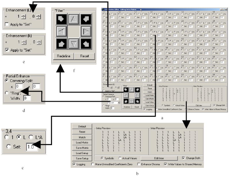
Interface developed for control of MPEG enhancement parameters and matrix coefficients with key sections enlarged to show details. Default settings are shown. (a) Full interface – inter and intra filter matrices (lower right corner) are selectable and editable. (b) Global controls and a preview of the filter matrices (shown in symbolic format, but actual values can also be shown if required). (c) Enlargement of one of 64 matrix element controls, where L represents the parameter λ and A the parameter α. (d) Controls to leave a portion of output unenhanced. (e) Setting of λ (original filter, Fig. 3) or k (scalar on manually set values, Section 2.2.4). (f) Shifting controls for moving a defined set of coefficients (‘filter’) around the 8×8 matrix.
The array of 64 identical control elements, representing the 8×8 point-wise multipliers of the quantization matrix or matrices (Fig. 4a) allows control of any single coefficient in the filter in use. For each coefficient, the user can choose to leave the value unmodified (‘1’), multiplied by λ (‘L’) or multiplied by a product of the two parameters: λ and α (‘L.A’). There is also a manual option where the value can be set to any numeric value, including zero. Multiplication of these manually set values by a scalar may also take place depending on the setting explained in section 2.2.4. The individual element controls (Fig. 4a, c) are populated with the filter’s coefficients; the default filter (Fig. 3) can be recalled at any time by clicking ‘Default’. A no-enhancement state can be examined by clicking ‘Reset’. This sets all of the multipliers to one. Single filter matrices or complete parameter sets can be saved and restored using the controls provided.
2.2.2 Filter Shifting
As part of our ongoing research into finding the most effective filter for patient viewing, we required the ability to move the entire set of coefficients along the upper-left to lower-right diagonal axis of increasing spatial frequency. This permits viewing the effects of coefficient sets over a range of spatial frequencies. The interface features a set of filter-movement controls (Fig. 4f) that can move an 8×8 group of matrix coefficients within a 24×24 area such that the original contents of that filter can be moved completely off the active area without losing the contents of the filter. Any ‘empty space’ created by such shifting is filled with ‘1’ coefficients. If a new preferred position is found, the button “Redefine” may be clicked to use that 8×8 set as that which is retained during further shifts. The result of shifting operations is demonstrated in Fig. 5.
Fig. 5.
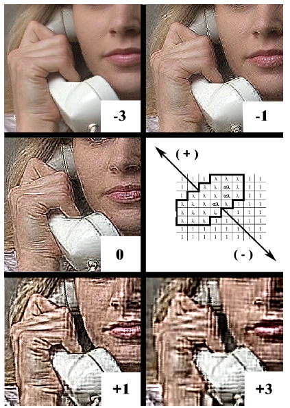
Small section of video output shown for clear visibility of details of changes whilst moving the set of coefficients (λ=10.0, α=1.5) along the block diagonal axis as shown. Positive values indicate shifting the matrix into areas of lower spatial frequency. Negative values indicate shifting the matrix into areas of higher spatial frequency. Note the very small visible effect once the filter is not modifying any information within the area of the top six diagonal lines (−3).
2.2.3 Partial Screen Enhancement
A recent study15 demonstrated a rapid adaptation of normally sighted observers to sharpening (and to blur). When observers adapted to a sharpened (or blurred) image for just two minutes, they judged a sharpened (or blurred) image to be substantially less so than before adaptation. This effect may account for the modest appreciation of enhanced images by patients with visual impairments in some previous studies3, 9, 11. In addition, it was shown that this successive adaptation phenomenon takes place across images with differing natural spectral slopes15 (the adaptation was still exhibited when viewing sharpened versions of a different image from the one used to induce the adaptation, and vice-versa). It is possible that the presence of a spatial (local) original image “anchor” could affect successive adaptation. This has the potential to reduce limitations of image enhancement when evaluated by investigation of the user’s preference for an enhanced image.
To this end, our implementation provides an ability to specify that a portion of the screen; a corner, margin (Fig. 6) or ‘ring’ should not be enhanced by the decoder (Fig. 4d). This should enable the user to see the enhanced portion of the screen alongside the original unenhanced portion. In this format, the effect of any enhancement should be apparent and may defeat the adaptation. We plan to compare patients’ appreciation of the enhancement when they are presented with and without this unenhanced portion to determine if the presence of the unenhanced image reduces adaptation and results in perception of higher image quality of the enhanced image.
Fig. 6.

This frame illustrates partial screen enhancement (to the right of the dashed line) and a situation (letters moving leftward) where partially enhanced macroblocks appear on the unenhanced section of the frame. Predicted blocks based on an enhanced reference from the right side of the line appear moderately enhanced on the left side of the line. The area where the effect is most obvious has been indicated with arrowheads. The dividing line has been added for clarity of the illustration; it does not appear on the screen.
MPEG presents some difficulties in implementing a ‘clean’ dividing line between two such regions. Inter-blocks are often based on blocks from a different location in the picture. If this location falls on a different side of the ‘line’, one of two things will happen. Either a partially enhanced block will appear on the unenhanced side (the reference block was decoded with enhancement, but the difference value in the inter-block was not modified), or a partially enhanced block will appear on the enhanced side (the reference block was not modified, but the difference value in the inter-block was decoded with enhancement). Both situations lead to a non-uniformity of enhancement around the dividing line, but in most cases we have found the effect to occur infrequently and thus be tolerable. An exception to this is in scenes with camera-pans, where columns of blocks are being used as references for locations just to the left or right of the line. This is an unfortunate side effect of the method we are using, and could only be overcome by seeking and decoding the reference block again without enhancement. As it is the decoded blocks (not the DCT values awaiting dequantization) that are stored, such a change would be practical only by making significant changes to the decoder, which is something we specifically set out to avoid. As vertical pans in video are rare, use of a horizontal margin or a full ring may assure that a complete margin of unenhanced video is available most of the time.
2.2.4 Filter Scaling
Our initial investigations into better DCT filtering techniques involved simple changes in the placement and range of locations of λ on the 8×8 filter matrix. It became clear however, that a smooth distribution of multiplier values, rather than a band of identical ones (Section 3.4) was preferred. By defining a filter in terms of fractions of a constant, and multiplying by that constant, we can achieve this functionality. The enhancement control (Fig 4e) is used to set a new variable k, and the ‘Set’ controls on each element (Fig 4c) are used to define the filter. If the “Apply to ‘Set’” option is checked (Fig. 4e), the new method is enabled, such that each coefficient,
| (1) |
This way setting any coefficient to 0 will yield no enhancement, and using negative values will introduce contrast degradation (the final coefficient is not permitted to be less than 0 by the interface).
3. Outcomes
We have successfully implemented the algorithm from the previous study10. A demonstration of this video output of the method is shown in Fig. 7; a comparison with the previous method is included, illustrating a replication (in real time) of the result achieved with the previous off line enhancement. A demonstration of the enhancement can be found on our website, http://www.eri.harvard.edu/faculty/peli/, in the ‘Videos/Simulations’ page.
Fig. 7.
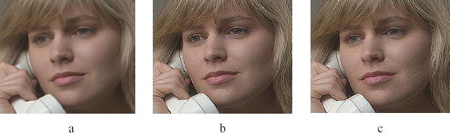
Illustration of MPEG based enhancement using the new method (libmpeg2) demonstrating replication of the previous10 (Restream™) method. (a) New method with λ=1.0, α=1.0. (Unenhanced image) (b) Previous method with λ=4.0, α=1.5. (c) New method with λ=4.0, α=1.5.
3.1 Application
An advantage of our approach was the ability to integrate the software library into more complete software “media players”, an example being VLC16. Most development work was completed using short MPEG-2 sequences stored in computer files as MPEG Elementary streams (ES). Streams are rarely presented in this simple format however, and are usually contained inside Program Streams (PS). These are used for DVD content and are designed to include a ‘program’ of information including audio and other additional data. Such streams may in turn be contained within Transport Streams (TS); these are designed to be resilient to transmission errors encountered in broadcast over a distance using cable, satellite and terrestrial distribution.
By recompiling VLC with our modified library, raw MPEG-2 ES data extracted from higher level streams can be passed to the library for decoding. Uncompressed video data is returned from the library back to the player for output. This has made it possible to apply the enhancement to any MPEG-2 source readable by the player. We have successfully enhanced material directly from a playing DVD using this approach.
3.2 Interlacing Artifacts
When viewing an interlaced source on a non-interlaced/progressive display (without the use of a suitable de-interlacing filter), consecutive video lines derived from the two different fields will not align horizontally. Enhancement exacerbates this problem by enhancing lines that run vertically (which are prone to such artifacts, Fig. 8). We believe this may have been largely to blame for the ‘motion artifacts’ noted in the previous study10. Most of our subjective viewing and demonstrations have been conducted using a NTSC (interlaced) 27″ CRT television, rather than progressive computer monitors. This resulted in the substantial reduction of the interlacing artifacts exhibited on progressive computer monitors (as done previously). The improvement might be noted on a progressive screen as well by using a deinterlacing filter on the video output as shown in Fig. 8.
Fig. 8.

Enhancement and reduction of interlacing (“motion”) artifacts. Shown are three segments of frames from a motion event. Areas where the effect is particularly prominent have been encircled for emphasis and comparison. (a) Interlacing artifacts caused by the combination of two fields from two different instants in time. (b) Enhancement (λ=4.0, α=1.5) without deinterlacing accentuates these artifacts. (c) Using VLC ‘linear’ deinterlacing filter reduces these interlacing or “motion” artifacts.
3.3 Inter-Picture Artifacts
MPEG video enhancement exhibits some artifacts that are related to the predictive ‘motion’ decoding, but are not motion specific. Paradoxically these artifacts are particularly noticeable with static or low-motion videos, appearing as very rapid changes in macroblock appearance.
MPEG compression results in some losses, meaning that the decoded pixel values will not exactly match the input pixel values. The size of this loss will depend on the bandwidth allocated to the stream (this governs how the quantization matrices are defined). Inter-blocks therefore must be based on the information that will be available to the decoder, rather than the original pixel values presented to the encoder. To allow for this, an MPEG encoder features a built-in decoder. Inter-blocks are not based on the difference from the original pixel values that were encoded, but instead on the difference between current blocks and the decoded output of the already encoded reference blocks. A buffer memory exists in decoders to store recently encoded pictures for when a decoded version is required.
When an inter-block is encoded, the value is usually composed of two components. The first is the change in the image, due to the imperfect match found by the block-matching search. The second is a compensation for the losses made in previous encoding. This second component is usually irrelevant; if the block has changed it makes little sense to talk about the error value when the block was first encoded. However, for still video, or video with little motion, the bulk of the inter-block information will be the encoder’s compensation for these earlier coding/quantization errors, which might create a problem for our enhancement.
The simplest case of the problem is found when considering two (originally) identical sequential pictures presented for decoding; the first an intra-picture, and the second an inter-picture, using only this previous intra-picture as a reference. For each block of uncompressed pixels in the first picture, a coded intra-block exists, with some loss of information dependent on the nature of the quantization matrix used. When the encoder moved on to the next picture, there would have been a difference between the block being encoded (uncompressed) and the reference block (decompressed by the internal decoder). This difference is equal to the error value made in the encoding of the block in the first picture, and is now encoded as the inter-block information for the second, inter-picture. This difference is usually very small. When we enhance the intra-block using a modified quantization matrix, we enhance (increase the contrast of) any error made in encoding. It is logical and correct to assume that if we process the “error” value in the blocks from the subsequent inter-picture in the same manner as the original, we will scale the value in such a way as to correct the (now larger) error in the modified intra-block (the DCT is a linear operation). However, as this error is so small in magnitude, the resolution allocated to it within the MPEG stream (designed to hold ‘large’ significant changes) is insufficient for an accurate correction to be made, so some change will result, which we perceive as noise. If we now extend our simplest case to real MPEG sequences where most GOP orders specify one intra-picture followed by many inter-pictures, we see that the problem is cumulative, as the blocks these contain are based on surrounding blocks, not the first intra-block in the GOP. This can lead to objectionable temporal inconsistencies in the output seen as noise that appears over the course of a GOP (usually less than a second) and suddenly disappears (with the appearance of each new intra-picture). Videos illustrating the problem (using a still image simplest case as discussed above) can be found on our website, http://www.eri.harvard.edu/faculty/peli/, under the ‘Videos/Simulations’ page. These effects are not noticeable within motion sequences as the small effect is masked by the larger change due to the motion. However in still or low-motion sequences these small temporal changes are easily detectable. Although the effect might appear to be a significant problem, the small block-to-block changes may not have sufficient contrast to enable them to be seen by visually impaired patients. We will elicit patient impressions of any “artifacts” they notice in our future studies. If they are noticeable, we may seek to reduce such artifacts as part of the decoding process by examining the inter-block content and motion vector information encoded with the inter-blocks to reduce the enhancement for those blocks with little real ‘change’. For a completely still image, the enhancement can be dispensed with completely for the inter-pictures.
3.4 Ringing artifacts and filter development
The previous multiplier matrix (Fig. 3) sometimes generated undesired effects, exhibiting ringing at high contrast edges in the picture. The effect appeared as jagged edges on curves (where the area of the MPEG block not containing the edge became darker or lighter, and did not match well with neighboring blocks), and as extra straight lines on straight edges. Both effects are illustrated in Fig. 9. The effect was especially noticeable with large text, as it contains both features.
Fig. 9.
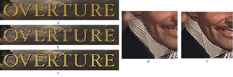
Illustration of ringing artifacts and their reduction. (a) Unenhanced section of frame with text. (b) Text is particularly prone to ringing artifacts caused by enhancing too limited a band of frequencies in the DCT block. (c) Our more recent filtering techniques (example Fig. 10) have substantially reduced these ringing artifacts, without reducing the contrast enhancement effect. (d) Curved edges appear ‘jagged’ when ringing artifacts are caused by the DCT filtering. (e) The more recent filtering applied has reduced these artifacts.
We found that by only enhancing a band of spatial frequencies in the DCT block, we were failing to correctly enhance sharp edges, as these contain high frequencies in order to form a sharp transition. The solution required a wider band-enhancement, giving a new filtering scheme (Section 2.2.4) and implemented using a smoother high-pass filter (Fig. 10). The results of using this filtering are shown in Fig. 9. Comparing Fig. 9b and c demonstrates that with the new filter we achieve a similar contrast enhancement, but with far fewer ringing artifacts. We know from patient feedback during development that these ringing artifacts were visible and objectionable. As we set out to provide an enhancement that appears similar to the previous adaptive enhancement algorithm3, 6 (Fig. 1), it is clear that this filter provided enhancement that is closer to the intended result. One drawback of using such a wide-band filter is that it can increase noise for some highly compressed streams, amplifying errors due to harsh quantization as discussed in Section 3.3. As we continue our efforts to find the most effective filter for patient viewing, some compromises may have to be made, or a range of filters provided to be selected according to the compression level of the source material.
Fig. 10.
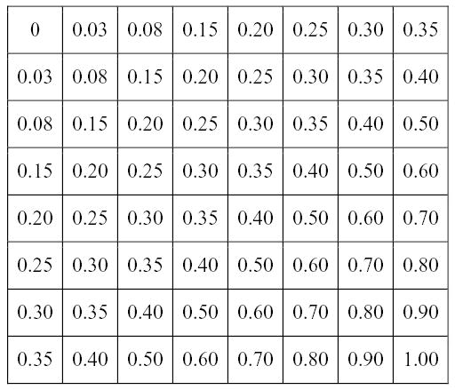
Example of new filter developed using our implementation. This provides smoother, high pass filtering of the DCT transformed blocks than that of Fig. 3. Using the scheme set out in Section 2.2.4, each coefficient in the table is multiplied by the scalar k (set by the user interface, Fig. 4e), and the result increased by one. Values of 10 ≤ k ≤ 40 have been found to provide a useful enhancement in lab pilot tests.
4. Discussion
MPEG coding is lossy (Section 1.1). MPEG-2’s goal was to produce an output that was perceptually very similar to the input, but not identical. As such, the information available to any decoder is imperfect, and enhancing such information will enhance any coding error made. Applying a contrast enhancement algorithm to a fully decoded picture enhances block artifacts that are otherwise less noticeable. Applying this algorithm within block decoding substantially reduces that problem, but cannot eliminate errors within a block due to quantization. The worst example of this is in the case of inter-pictures with low-motion video, considered in section 3.3. The problem of enhancing errors worsens with the decrease in bandwidth allocated to MPEG streams. Complaints already abound from TV viewers concerning broadcast (where bandwidth is at a premium) digital video “artifacts”. Enhancement may prove objectionable with some of these extremely low bit-rate streams.
The size (in pixels) of MPEG blocks significantly limits the range of available spatial frequencies for enhancement, using our method. Previous implementations using analog video have not had such limitations imposed on them, allowing the user to adjust the enhancement over a greater range of spatial frequencies and change the spatial frequency range itself7. However, we believe the range of frequencies available is useful over a range of TV sizes and seating distances (see Section 1.3).
5. Conclusions
We have successfully implemented the algorithm from our previous work10, in real time, demonstrating that the technique was indeed computationally inexpensive. We addressed and investigated problems with the previous implementation, including motion artifacts and edge ringing artifacts (by using the interface to examine the most suitable arrangement and values of the filter matrices). Work continues to improve the filtering aspects and reduce the problems with inter picture decoding (Section 3.3). We have made the enhancement adjustable with a remote control; this has aided testing and allows patients in the lab to control the enhancement with ease (verified by several informal sessions with such patients).
We are beginning a new study examining use of the enhancement, including patient impressions of the enhancement, the effect of an unenhanced ring surrounding the video under patient control, and whether more or less enhancement is required for different types of video. We have prepared sequences that we hope will be both stimulating and interesting for patients by using segments from film and television that they are used to seeing in the home.
6 Licensing and patent issues
We have used a licensed encoder to generate test MPEG-2 streams. We are a licensee of the MPEG licensing authority (MPEG-LA), permitting us to produce (compile) our decoders without violating patent laws.
Acknowledgments
We thank J. H. Kim for advice and assistance in the early stages of this project. Supported in part by NIH grants EY05957 and EY12890.
References
- 1.American Foundation for the Blind, “Who’s Watching? A Profile of the Blind and Visually Impaired Audience for Television and Video,” See http://www.afb.org/section.asp?SectionID=3&TopicID=140&DocumentID=1232 [Google Scholar]
- 2.Peli E, Peli T. “Image enhancement for the visually impaired,”. Optical Engineering. 1984;23(1):47–51. [Google Scholar]
- 3.E Peli, “Recognition performance and perceived quality of video enhanced for the visually impaired.,” Ophthalmic and Physiological Optics (in press), (2005). [DOI] [PMC free article] [PubMed] [Google Scholar]
- 4.Peli E, Goldstein RB, Young GM, Trempe CL, Buzney SM. “Image enhancement for the visually impaired - simulations and experimental results,”. Investigative Ophthalmology & Visual Science. 1991;32(8):2337–2350. [PubMed] [Google Scholar]
- 5.Peli E, Lee E, Trempe CL, Buzney SM. “Image enhancement for the visually impaired: the effects of enhancement on face recognition,”. Journal of the Optical Society of America. 1994;11(7):1929–1939. doi: 10.1364/josaa.11.001929. [DOI] [PubMed] [Google Scholar]
- 6.Peli E. “Adaptive enhancement based on a visual model,”. Optical Engineering. 1987;26(7):655–660. [Google Scholar]
- 7.Hier RG, Schmidt GW, Miller RS, Deforest SE. “Realtime locally adaptive contrast enhancement: a practical key to overcoming display and human-visual-system limitations,”. SID Symposium Digest of Technical Papers. 1993;(491–494) [Google Scholar]
- 8.Sikora T. “MPEG digital video coding standards - delivering picture-perfect compression for storage, transmission, and multimedia applications,”. IEEE Signal Processing Magazine. 1997;14(5):82–100. [Google Scholar]
- 9.Tang J, Kim J, Peli E. “Image enhancement in the JPEG domain for people with vision impairment,”. IEEE Transactions on Biomedical Engineering. 2004;51(11):2013–2023. doi: 10.1109/TBME.2004.834264. [DOI] [PubMed] [Google Scholar]
- 10.Kim J, Vora A, Peli E. “MPEG-based image enhancement for the visually impaired,”. Optical Engineering. 2004;43(6):1318–1328. [Google Scholar]
- 11.Peli E, Kim J, Yitzhaky Y, Goldstein RB, Woods RL. “Wideband enhancement of television images for people with visual impairments,”. Journal of the Optical Society of America. 2004;21(6):937–950. doi: 10.1364/josaa.21.000937. [DOI] [PubMed] [Google Scholar]
- 12.S Hildebrarnd, “Restream,” See http://shh.sysh.de/ [Google Scholar]
- 13.A Holtzman, M Lespinasse & team, “libmpeg2 - a free MPEG-2 video stream decoder,” See http://libmpeg2.sourceforge.net/ [Google Scholar]
- 14.Free Software Foundation, “GNU General Public License,” See http://www.gnu.org/copyleft/gpl.html [Google Scholar]
- 15.Webster MA, Georgeson MA, Webster SM. “Neural adjustments to image blur,”. Nature Neuroscience. 2002;5(9):839–840. doi: 10.1038/nn906. [DOI] [PubMed] [Google Scholar]
- 16.A Cellerier & team, “VLC media player,” See http://www.videolan.org/vlc/ [Google Scholar]