Abstract
In the paper, we present a new hardware acceleration method to speedup the ordered-subsets expectation-maximization (OS-EM) algorithm for quantitative SPECT (single photon emission computed tomography) image reconstruction with varying focal-length fan-beam (VFF) collimation. By utilizing the geometrical symmetry of VFF point-spread function (PSF), compensation for object-specific attenuation and system-specific PSF are accelerated using currently available PC video/graphics card technologies. A ten-fold acceleration of quantitative SPECT reconstruction is achieved.
Keywords: SPECT, Varying focal-length fan-beam collimation, OS-EM reconstruction, PC hardware-based acceleration
1. Introduction
Varying focal-length fan-beam (VFF) collimation was proposed ten years ago for cardiac SPECT (single photon emission computed tomography) imaging with the following observations [3, 4]. As compared to parallel-hole (PH) collimator, VFF geometry improves counting statistics of the heart region by a factor of two with an equivalent spatial resolution. As compared to fan-beam (FB) collimator, VFF geometry with an equivalent spatial resolution acquires more counts from the regions where the FB collimation encountered truncation and improves signal-to-noise ratio in a filtered back-projection (FBP) image reconstruction without introducing truncation artifacts [29, 30].
The iterative ML-EM (maximum-likelihood expectation-maximization) reconstruction algorithm [12, 20] for SPECT is widely utilized to model the projection physics and achieve good quantitative reconstruction. Through formulating the source-detector projection relation between the emission-source and acquired-data vectors as a matrix-vector relationship, it is able to compensate for the object-specific attenuation and system-specific PSF (point-spread function) variation within each iterative re-projection and back-projection cycle. However, the ML-EM algorithm has several limitations in clinical use. One is the enormous size of vectors and matrices and the associated intensive computing burden for a high-resolution image reconstruction. Research efforts have been devoted to mitigate this drawback by (1) developing efficient simulators for the re-projection and back-projection cycle, e.g., by the use of the geometry warping with distance-dependent convolution [31], the recursive ray-tracing with geometry symmetries [5, 6, 21], etc; and (2) investigating sophisticated strategies to speedup the convergence to a satisfactory result, such as the ordered subsets (OS) technique [9]. A significant speed gain was observed by the OS-EM algorithm, but the reconstruction time was still too long even for an image array size of 64 cubic [8]. Further acceleration is needed.
With the development of computer graphics software and hardware technologies [22], modern PC video/graphics card can provides us with a powerful tool to perform multi-dimensional image processing and rendering tasks, which were used to be done on a high-end graphics workstation or specially designed hardware. Using the PC graphics-card hardware to accelerate image reconstruction is currently an interesting research topic. Cabral, et al. [1] proposed an acceleration method, which uses the texture-mapping capability of graphics hardware to speedup the FBP reconstruction. Taking the advantage of two-dimensional (2D) texture-mapping techniques of PC hardware, Mueller, et al. [17] presented an acceleration method to speedup the iterative SART (simultaneous algebraic reconstruction technique) for cone-beam CT (computed tomography). Recently, Xu, et al. [27] implemented a fast reconstruction framework for 3D CT imaging on the latest generation of PC graphics card. Chidlow, et al. [2] presented an acceleration strategy for SPECT reconstruction by the PC graphics card for both FBP and OS-EM algorithms. In their OS-EM implementation, only attenuation compensation is considered for PH collimation. Our previous work [25] has shown more than ten times speedup for FBP-based VFF-collimated quantitative SPECT reconstruction. Preliminary results of speedup the OS-EM algorithm for VFF collimation was presented recently in a conference abstract [23].
In this paper, the PC hardware-based acceleration method [23] for the OS-EM reconstruction of VFF collimated quantitative SPECT is detailed with accurate compensation for both the non-uniform attenuation and variable PSF effect. Comparing to the work of Chidlow, et al. [2], our method fully implements the corrections of attenuation, PSF effect and scatter with latest graphics processor utility (GPU) functionalities. Using the powerful multi-dimensional image processing capabilities and fully 32 bit precision support of the GPU, our acceleration method has achieved a speedup of more ten times than our previous CPU-based accelerating methods [5–8].
The contents of this paper are organized as follows. Section 2 presents a brief description of our PC graphics card GPU-based acceleration method for VFF-collimated quantitative SPECT reconstruction. Implementation and validation of the acceleration method by Monte Carlo (MC) simulations are reported in Section 3, followed by conclusions in Section 4.
2. Method
2.1. Preliminaries on the OS-EM Image Reconstruction Algorithm
By the ML-EM algorithm [12, 20], the emission source distribution {fijk} can be reconstructed iteratively from the projection data {plmn} as follows:
| (1) |
where the projection coefficient hijk,lmn is the fraction of photons that emit from voxel (i,j,k) and trigger counts in detector bin (m,n) at view angle l (hereafter denoted as detector bin (l,m,n) for simplicity) and I is the iteration number. The scatter contribution {slmn} in the measured count {plmn} is included as a known parameter, which can be estimated by a multiple energy-window acquisition protocol [8, 10, 11, 13, 15, 16, 19]. By the OS strategy [9], the detector bins are grouped into G groups or subsets {Sα: α = 1, 2, ..., nG}. The resulting reconstruction algorithm, OS-EM, consists of a series of iterations, each of which includes nG pairs of re-projection and back-projection operations:
For subset α = 1,2,...,nG
| (2) |
where after α runs from 1 to nG, a full iteration is completed for index I, i.e., is assigned to . Then α starts again from 1 to nG for the next iteration result of
In the follows, we will focus on the acceleration of the OS-EM algorithm only. The ML-EM algorithm can be considered as a specific case of the OS-EM algorithm, where all detector bins are grouped into one group.
2.2. Reduction of PSF Matrix Size
In equation (2), each projection matrix element hijk,lmn is the product of the PSF psf(i,j,k,l,m,n) and the accumulated attenuation factor, i.e.,
| (3) |
where {(uq,vq,wq,dq)} is the list of voxel indices and intersecting lengths on the path from voxel (i,j,k) to detector bin (l,m,n).
The high dimension nature of the PSF matrix limits the possibility of loading the whole matrix into computer memory and each element of this matrix must be re-calculated at each iteration or on-the-fly. The repeated calculation of PSF matrix in the iterative re-projection and back-projection cycle is extremely time-consuming. It is crucial to reduce the dimension or the size of the PSF matrix for efficient reconstruction.
The geometrical symmetry in 3D space is one important characteristics of the PSF matrix [5–8]. In the PSF matrix, the value of each element is only determined by the relative position between the voxel in the reconstructed image and the detector bin in the sinogram space. Thus, only one view’s PSF matrix elements are needed to be stored. For other views, the re-projection and back-projection operations can be performed using the same matrix on the rotated attenuation map and iteratively-reconstructed image dataset, as shown in Figure 1. Thus the original PSF matrix can be compressed into a 5D matrix: psfa(i,j,k,m,n) [28, 31].
Figure 1.
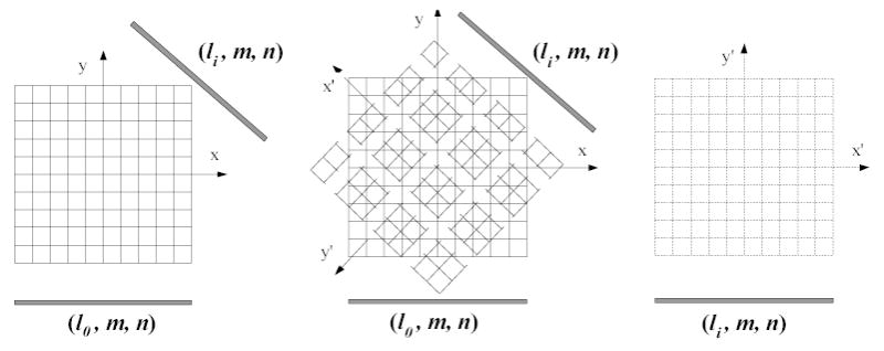
Angular symmetry of the PSF matrix for different views. Left is the original dataset lattice. Middle shows the rotating and re-sampling process for a different view. Right is the rotated dataset lattice.
Besides the above angular symmetry, there exists slice symmetry, which can be utilized for further reduction of the PSF matrix size. Given two voxels that have the same (i0, j0) but at two different slices k0 and kl respectively, the value of psfa(i0 , j0, k0, k0 + δm, n) is equal to that of psfa(i0, j0, kl, kl + δm, n) due to their similar spatial relationship. Taking advantage of this feature, the PSF matrix can be further compressed to a 4D matrix psfb(i, j, δm, n), where δm is the relative slice distance between voxel (i,j,k) and detector bin (m,n). Thus for each voxel (i,j) on a slice, its PSF effect on the detector plane can be represented as psf(i,j)(δm, n), which is defined as the PSF mapping image of voxel (i,j) at that slice, see Figure 2(a). In practice, the values of most pixels (δm, n) of the PSF mapping image is zero due to the geometrical structure of the collimated detection, as seen in Figure 2(b). The entire PSF matrix is then transformed to a new form:
Figure 2.

Illustration of a compressed PSF mapping image for a given voxel (i,j) in an image slice. (a) The original PSF mapping image for that voxel. In practice, most part of this image is zero. The non-zero part is indicated as the shadowed region in (b). (c) The non-zero region of the PSF mapping image for each voxel in an image slice. Only this non-zero region will be kept in the compressed PSF matrix.
| (4) |
where and are the width and height of the non-zero part of the original PSF mapping image. Their values are usually far less than the slice number and the bin number respectively.
Comparing to the original PSF matrix, the size of the compressed PSF matrix is much smaller. Our experimental studies show that the size of the whole compressed PSF matrix can be less than 128 Mbytes for reconstruction geometries whose dataset size is up to a 512×512×512. Since the whole compressed PSF matrix does not change during the entire iteration procedure, it can be calculated at pre-processing stage and loaded into the computer memory prior to the iterative process.
2.3. Hardware-Accelerated Calculation of Accumulated Attenuation Factor
Calculation of the accumulated attenuation factor in equation (3) for each voxel is also a time-consuming task. According to our experimental studies, computing the accumulated attenuation factors takes more than three quarters of the total reconstruction time of the OS-EM algorithm. Unlike the PSF matrix, the accumulated attenuation factor is not only position-dependent, but also attenuation map-dependent. It is difficult to accelerate the calculation of the accumulated attenuation factor for VFF geometry in the pre-processing stage, as we did for the PSF matrix. Zeng et al. [31] explored a warping strategy to transform fan- and cone-beam geometries into PH collimation, so that the well-developed PH compensation techniques can be adapted to the transformed attenuation map and iteratively-reconstructed image. For VFF geometry, warping the PSF effect and the accumulated attenuation factors is not a trivial task. The associated computation can be intensive and the accuracy can be compromised. Computing the factors on-the-fly is needed. To accelerate the calculation of the accumulated attenuation factors, we rely on the powerful graphics card technologies.
For a voxel (i,j,k), its accumulated attenuation factor to detector bin (l,m,n) is a summation of multiplications of those attenuation coefficients and intersecting lengths on the path from voxel to the bin, as shown in Figure 3. This non-uniform sampling of intersecting lengths causes a challenge for any acceleration attempt. To mitigate this difficulty, an even-sampling strategy is employed. The path from voxel (i,j,k) to detector bin (l,m,n) is sampled evenly with fixed length unit (which can be one voxel unit). The attenuation values of the sampled points are determined by interpolation from the original attenuation values. Each interpolated individual attenuation factor may be different from its original value, but the accumulated factor along the path matches the original one, see Figure 3. Thus the accumulated attenuation factor can be calculated by:
Figure 3.

Illustration of an even-sampling strategy for fast calculation of the accumulated attenuation factor. (a) The accumulated attenuation factor from a non-evenly sampled path. (b) The accumulated attenuation factor from an evenly-sampled path.
| (5) |
where p represents the evenly-sampled points on the path from voxel (i,j,k) (or p0) to detector bin (l,m,n) (or pn), and δd is the length unit, reflecting the distance between two adjacent re-sampled points. Since δd is fixed during all iterations, it is advantageous to implement all the exponential calculations in equation (5) in advance before the iteration starts. For each voxel in the attenuation map, its value μ is replaced by e−μ·δd . This new map {e−μ·δd} is called an exponential attenuation map.
Using the exponential attenuation map, the calculation of the accumulated attenuation factor for each voxel is implemented with the PC graphics hardware as follows. For each voxel, a series of projection rectangles are determined, on which the corresponding exponential attenuation maps are mapped as 2D textures, as shown in the left picture of Figure 4. Each rectangle will be projected onto the projection plane, correspondingly the mapped exponential attenuation maps will be projected and interpolated. Using the texture multiplication techniques, all the projected images of the projection rectangle are multiplied together to create the accumulated attenuation image, as shown in the right picture of Figure 4.
Figure 4.
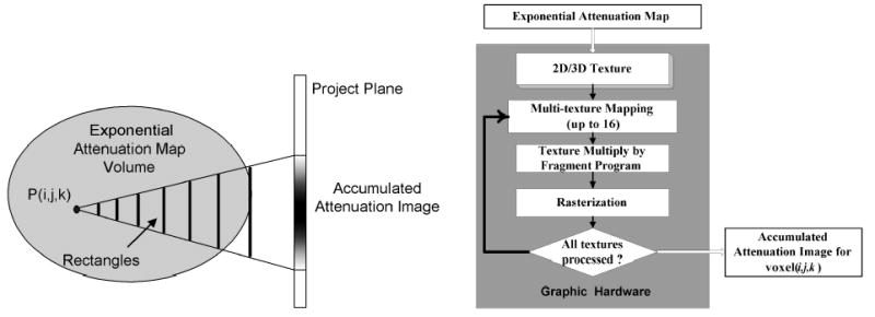
Left shows the generation of a accumulated attenuation image for voxel (i,j,k). The illustration of the hardware-accelerated generation method on the PC graphics card is shown in the right picture.
The 2D/3D texture mapping technology is one of the important graphics technologies which have been well-optimized by the modern graphics hardware. Modern GPU, such as Nvidia GeforceFX series, supports up to 16 textures on one rectangle. At the same time, the GPU provides powerful texture processing capabilities, such as fragment program and vertex program, to implement the “hardware program”. Through its programming library, we can instruct the “hardware” to perform many useful operations, such as multiplication, summation, etc [18]. In this work, we utilize the multiple texture and fragment program technology [18] to further accelerate the performance. For each rectangle, we map up to 16 attenuation images on it. Using the fragment program, all images can be projected and multiplied. The result will be re-mapped to the next possible rectangle with others 15 new textures until all the texture have been multiplied. Because all these operations are performed by the GPU hardware with its special designed structure, the whole calculation procedure can be accelerated dramatically.
2.4. Hardware-Accelerated OS-EM Reconstruction Algorithm
Based on the above description on PSF matrix and accumulated attenuation factors, the re-projection procedure in the OS-EM algorithm can be is summarized as:
| (6) |
Given a view angle l, the estimated source f(i,j,k) and the exponential attenuation map will be rotated to parallel to the surface of the collimator and re-sampled as shown in Figure 5. From equation (6), the final re-projection image of this view is the sum of the re-projected images, which is the multiplication of the PSF mapping images and the corresponding accumulated attenuation images, from all voxels in the reconstruction space. The calculation of the re-projection image for each view angle is accomplished as follows.
Figure 5.

Illustration of texture mapping technology for rotating and re-sampling an image.
From the rotated exponential attenuation map, the accumulate attenuation image for each voxel (i,j,k) is generated as described in Section 2.3. Using the multi-texture and fragment program, the corresponding compressed PSF mapping image and accumulate attenuation image are mapped on a rectangle and multiplied to generate the re-projected image of that voxel. By adding all the re-projected images of all voxels with the corresponding weights f(I,α)(i, j,k), the re-projection at this view angle l is finally accomplished, see Figure 6.
Figure 6.

Illustration of the re-projection procedure for each view angle. Left shows the generation of the re-projection image of voxel (i,j,k). Right shows the generation of the re-projection image for one view.
Comparing to the re-projection procedure, the back-projection procedure provides the correction factors for the estimated image as shown in equation (2). The back-projection operates on the ratio of the measured data and the re-projected data and can be described as:
| (7) |
Similar to the re-projection operation, the exponential attenuation map is rotated for each view, and the re-projected image of each voxel in the rotated objects is generated. After multiplication with the ratio image (the measured data and the re-projected data) of this view, a correction factor volume is generated, which is given by the right term, second line of equation (7). This correction factor volume should be rotated back to its original angle for each ordered-subsets group to complete the back-projection. The flowchart of the accelerated OS-EM algorithm is shown in Figure 7.
Figure 7.
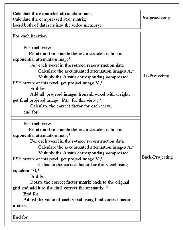
Flow chart of the accelerated OS-EM reconstruction algorithm using the graphics hardware. Symbol * indicates that this function is implemented by the GPU using its specific programming library.
By the powerful texture-mapping capabilities of the PC graphics card, all the rotation, multiplication, and addition operations on the volume images can be executed using GPU only. Since the GPU has its special structure for image processing and manipulation, the whole re-projection and back-projection time can be performed efficiently. At the same time, we utilize the float p-buffer, which supports 32 bit precision per color channel, to implement the data generation instead of the traditional color frame buffer (which only supports 8 bit precision per color channel) with buffer extension [2, 17]. This ensures the high calculation precision for the final result without loss of efficiency.
3. Experiments
The presented hardware-based acceleration method was implemented by MS Visual C++ on a Pentium IV platform (1GB RAM memory, 2.6GHz CPU speed) with an Nvidia@ GeforceFX 5900 graphics card (256MB video memory). Projections were simulated by the SIMIND MC program from the MCAT digital torso phantom to evaluate the efficiency of the presented acceleration method. The MCAT phantom had an array size 64×64×32 and 128×128×64 respectively. For each phantom size, the emission distribution was generated by selecting different emission concentrations in the heart, lungs and liver regions, respectively, that reflects the concentrations of a clinical setting [26]. The attenuation map was given by the object geometries in the phantom, and scatter was simulated up to the second order. The VFF collimation with low energy ultra-high resolution [7, 8] was modeled in the MC simulation. The focal-length function of the VFF collimator varied quadratically from 60 cm at the collimator center to 200 cm at the edge, F(r)=a+b|r|2, where r represents the location of detector bin. The size of the collimator was 52×38 cm2, mimicking the Siemens’ E-CAM SPECT system. A circular scanning orbit was considered with 64 and 128 views, respectively, evenly distributed on 360 degrees for the corresponding phantom size. The radius of rotation was 25 cm. The images were reconstructed into 64×64×32 and 128×128×64 arrays for the two phantom sizes, respectively. In order to utilize the system geometrical symmetries, the number of the ordered subsets shall be four or eight, where the projections in each subset have the same geometrical symmetry. By our previous studies [7, 8], the choice of either four or eight subsets did not make noticeable difference in reconstruction quality and reconstruction time. So the projections were grouped into eight ordered subsets in this study.
A standard implementation of the OS-EM reconstruction algorithm was performed first by Siddon’s ray-tracing technique for both attenuation factor and PSF effect for each image voxel and detector bin, without considering the central-ray approximation, the system geometrical symmetries and any ray-tracing optimization [5, 6]. (The scatter was estimated by the triple energy-window strategy [15, 16]). A visually satisfactory reconstruction was obtained after 4 iterations, starting from a uniform distribution across the FOV (field-of-view) [7, 8]. Assuming the 4-th iterated OS-EM result as a reference, another OS-EM reconstruction utilizing the system geometrical symmetries and an optimized Siddon’s ray-tracing technique [6–8] (i.e., a software CPU-based acceleration method) was performed up to 4 iterations, which provides an accurate quantitative reconstruction and also the gold standard to measure the speed gain by other acceleration methods. Then another software CPU-based acceleration method was performed up to 4 iterations, which is based on the matrix rotation and distance-dependent deconvolution with the central-ray approximation [28, 31]. Finally the presented hardware GPU-based acceleration method was performed up to 4 iterations. All the two software- and the one hardware-based acceleration methods for the OS-EM reconstruction generated visually the same image quality after 4 iterations. The results of the first software-based and the hardware-based accelerations for reconstruction of 64 cubic image are shown in Figure 8. Figure 9 reflects more quantitatively their similarity by both horizontal and vertical profiles through the images in the middle column of Figure 8. Their quantitative similarity is expected because they were implemented by 32-bit float precision.
Figure 8.
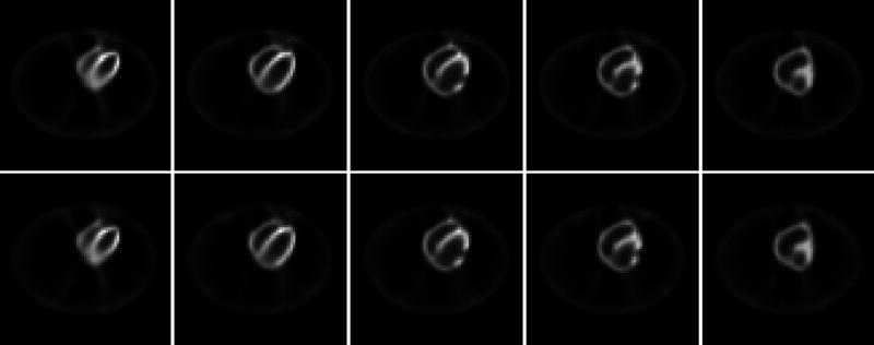
Reconstructed images of the presented hardware-based accelerating method and our previous software-based accelerating method [5–8]. All images in the top row are from the software-based accelerating method. The results of the presented hardware-based method are shown in the bottom row.
Figure 9.
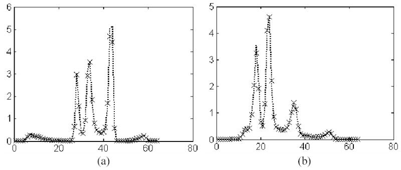
Profiles of the images in the middle column of Figure 8. Picture (a) shows the horizontal profiles through left ventricle near the apex, and picture (b) shows the vertical profiles through the left-ventricle center. The dotted curves show the result of the software-based method (top middle) and the crosses show the result of the hardware-based method (bottom middle).
The reconstruction times of these three acceleration methods for both 64 and 128 array sizes are listed in Table 1. To test the performance of the three methods for a larger data size, we doubled the slices of each phantom to 64×64×64 and 128×128×128, respectively, and repeated the data simulation and image reconstruction. Thus there are totally four phantom studies on the software- and hardware-based acceleration methods.
Table 1.
Comparison of reconstruction time between two software-based accelerating methods (second and third columns) and the presented hardware-based accelerating method.
| Data Size | Time Per Iteration (Based on 4 iterations) | |||
|---|---|---|---|---|
| Method with Geometry Symmetries & Fast Ray-tracing Technique | Method with Rotation & Distance-dependent Deconvolution | Method with Graphics Card Technologies | Pre-processing Time (presented method) | |
| 64×64×32 | 49.1s | 188.5s | 12.2s | 0.31s |
| 64×64×64 | 275.2s | 431.4s | 24.6s | 0.31s |
| 128×128×64 | 6.73 hours | 1.8 hours | 292.8s | 0.57s |
| 128×128×128 | 34.83 hours | 3.6 hours | 587.2s | 0.57s |
As shown in the table, the presented PC graphics card-based accelerating method achieved an additional speedup of more than ten times per iteration over our previous software-based accelerating method (with geometrical symmetries and fast ray-tracing technique) [5–8] for 64 image array size. The speed gain increases dramatically as the reconstruction volume increases. The geometrical symmetries and fast ray-tracing technique had a speedup of more than eight times per iteration over the standard implementation by the Siddon method without any acceleration [8]). The second software-based accelerating method using matrix rotation and distance-dependent deconvolution was slower than the fast ray-tracing method for a smaller array size because of the cost in the matrix rotation, and improved the reconstruction speed for a larger array size. These experimental results demonstrated the potential of the hardware-based accelerating method for efficient reconstruction of VFF-collimated quantitative SPECT for cardiac (or general chest) imaging.
4. Conclusion
By the reduction of the PSF matrix size, the use of the exponential attenuation map, and the hardware-accelerated matrix rotation, interpolation and calculation of the accumulated attenuation factors, the OS-EM reconstruction of VFF-collimated quantitative chest SPECT can be performed in a clinically-acceptable speed for reconstruction of a 64 cubic image array size. Since a currently available PC video graphics card with 256 MB video memory can load the PSF matrix for image reconstruction with matrix size up to 256 cubic at the price of less than $300, this presented acceleration method is cost-effective and has the potential to provide high resolution quantitative SPECT reconstruction for clinical use. With rapid development of the PC graphics card technologies, the reconstruction speed is expected to be further accelerated by newer generations of the GPU architecture in the near future [27]. Furthermore, by analytical compensation for the non-uniform attenuation and spatially-variant PSF [14, 24] with the hardware-based acceleration [25], the reconstruction speed can be in real time for high-resolution dynamic SPECT imaging that uses array size far beyond 64 cubic.
Acknowledgments
This work was supported in part by NIH Grant HL51466 of the National Heart, Lung and Blood Institute. We thank Drs. B. Tsui, E. Frey, and K. LaCroix for providing the MCAT phantom, and Drs. M. Ljungberg and E. Frey for providing the SIMIND MC program. We also thank Dr. Gene Gindi for editing this paper. Dr. G. Han is now with the Computer Associates Inc. Islandia, NY 11749. Dr. T. Li is now with the Department of Radiation Oncology, Stanford University School of Medicine, Stanford, CA 94305.
References
- 1.Cabral B, Cam N, Foran J. “Accelerated volume rendering and tomographic reconstruction using texture mapping hardware”. Proceedings of Symposium on Volume Visualization. 1994:91–98. [Google Scholar]
- 2.Chidlow K, moller T. “Rapid emission tomography reconstruction”. Proceedings of the 2003 Eurographics/IEEE TVCG Workshop on Volume graphics (VG03) 2003:15–26. [Google Scholar]
- 3.Hawman PC, Hsieh J, Hasselquist BE. “The cardiofocal collimator: a novel focusing collimator for cardiac SPECT”. J Nuclear Medicine. 1992;33:852. (Abstract) [Google Scholar]
- 4.Hawman PC, Haines EJ. “The cardiofocal collimator: a variable-focus collimator for cardiac SPECT”. Physics in Medicine and Biology. 1994;39:439–450. doi: 10.1088/0031-9155/39/3/011. [DOI] [PubMed] [Google Scholar]
- 5.G. Han, Z. Liang, and J. You, “A fast ray-tracing technique for TCT and ECT studies”, Conf. Record IEEE Nuclear Science and Medical Imaging Conference, in CD-ROM, 1999.
- 6.Han G, Liang Z. “A fast projector and back-projector for SPECT with varying focal-length fan-beam collimators”. J Nuclear Medicine. 2000;41:194. (Abstract) [Google Scholar]
- 7.Han G, Zhu W, Liang Z. “Gain of varying focal-length fan-beam collimator for cardiac SPECT by ROC, Hotelling trace, and bias-variance measures”. J Nuclear Medicine. 2001;42:7. (Abstract, Young Investigator Award candidate) [Google Scholar]
- 8.G. Han, Image Reconstruction in Quantitative Cardiac SPECT with Varying Focal-Length Fan-Beam Collimators, Ph.D. Dissertation, State University of New York at Stony Brook, NY, 2001.
- 9.Hudson HM, Larkin RS. “Accelerated image reconstruction using ordered subsets of projection data”. IEEE Trans Medical Imaging. 1994;13:601–609. doi: 10.1109/42.363108. [DOI] [PubMed] [Google Scholar]
- 10.Jaszczak RJ, Greer KL, Floyd CE, Harris CC, Coleman RE. “Improved SPECT quantification using compensation for scattered photons”. J Nuclear Medicine. 1984;25:893–900. [PubMed] [Google Scholar]
- 11.King MA, Hademenos G, Glick SJ. “A dual photopeak window method for scatter correction”. J Nuclear Medicine. 1992;33:605–612. [PubMed] [Google Scholar]
- 12.Lange K, Carson R. “EM reconstruction algorithms for emission and transmission tomography”. J Comp Assist Tomography. 1984;8:306–316. [PubMed] [Google Scholar]
- 13.Li L, Han G, Liang Z. (2000), “Investigation of a new scatter estimation method from triple energy window acquisition”. J Nuclear Medicine. 2000;41:193. (Abstract) [Google Scholar]
- 14.Li T, Wen J, Liang Z. “Analytical compensation for spatially variant detector response in SPECT with varying focal-length fan-beam collimators”. IEEE Trans Nuclear Science. 2003;50:398–404. [Google Scholar]
- 15.Li T, Wen J, Han G, Lu H, Liang Z. “Evaluation of an efficient compensation method for quantitative fan-beam brain SPECT reconstruction,”. IEEE Trans Medical Imaging. 2004;24:170–179. doi: 10.1109/tmi.2004.839365. [DOI] [PubMed] [Google Scholar]
- 16.Li X, Han G, Lu H, Li L, Liang Z. “A new scatter estimation method using triple window acquisition to fit energy spectrum”. J Nuclear Medicine. 2001;42:194. (Abstract) [Google Scholar]
- 17.Mueller K, Yagel R. “Rapid 3D cone-beam reconstruction with simultaneous algebraic reconstruction technique (SART) using 2-D texture mapping hardware”. IEEE Trans Medical Imaging. 2000;19:1227–1237. doi: 10.1109/42.897815. [DOI] [PubMed] [Google Scholar]
- 18.“Nvidia OpenGL Extension Specification”, Manual of Nvidia Company, 2004.
- 19.Ogawa K, Harata Y, Ichihara T, et al. “A practical method for position-dependent Compton scatter correction in SPECT”. IEEE Trans Medical Imaging. 1991;10:408–412. doi: 10.1109/42.97591. [DOI] [PubMed] [Google Scholar]
- 20.Shepp LA, Vardi Y. “Maximum likelihood reconstruction for emission tomography”. IEEE Trans Medical Imaging. 1982;1:113–122. doi: 10.1109/TMI.1982.4307558. [DOI] [PubMed] [Google Scholar]
- 21.Siddon R. “Fast calculation of the exact radiological path for a 3D CT”. Medical Physics. 1985;12:252–255. doi: 10.1118/1.595715. [DOI] [PubMed] [Google Scholar]
- 22.A. Watt, 3D Computer Graphics, the third edition, Addison-Wesley Press, NY, 2000.
- 23.Wang Z, Li T, Han G, Liang Z. (2004), “PC graphics card–based acceleration for OS-EM image reconstruction of quantitative SPECT with varying focal-length fan-beam collimators”. J Nuclear Medicine. 2004;45:414. doi: 10.1109/TNS.2005.858231. (Abstract) [DOI] [PMC free article] [PubMed] [Google Scholar]
- 24.Wen J, Li T, Liang Z. “An analytical inversion of non-uniformly attenuated Radon transform for SPECT reconstruction with variable focal-length fan-beam collimators”. IEEE Trans Nuclear Science. 2003;50:1541–1549. [Google Scholar]
- 25.Wen J, Wang Z, Li B, Li T, Liang Z. “Speed up of an analytical algorithm for non-uniform attenuation correction using PC video/graphics card architecture”. IEEE Trans Nuclear Science. 2004;51:726–732. [Google Scholar]
- 26.Wollenweber SD, Tsui BMW, Lalush DS, Frey EC, Gullberg GT. “Evaluation of myocardial defect detection between parallel-hole and fan-beam SPECT using the Hotelling trace”. IEEE Trans Nuclear Science. 1997;45:2205–2210. [Google Scholar]
- 27.F. Xu and K. Mueller, “Towards a unified framework for rapid computed tomography on commodity GPUs”, Conf. Record IEEE Nuclear Science and Medical Imaging Conference, in CD-ROM, 2003.
- 28.Ye J, Liang Z, Harrington D. “Quantitative reconstruction for myocardial perfusion SPECT: an efficient approach by depth-dependent deconvolution and matrix rotation”. Physics in Medicine and Biology. 1994;39:1281–1293. doi: 10.1088/0031-9155/39/8/006. [DOI] [PubMed] [Google Scholar]
- 29.You J, Bao S, Liang Z. “Benefits of angular expression to reconstruction algorithms for collimators with spatially varying focal-lengths”. IEEE Trans Medical Imaging. 1997;16:527–531. doi: 10.1109/42.640742. [DOI] [PubMed] [Google Scholar]
- 30.Zeng GL, Gullberg GT. “A backprojection filtering algorithm for a spatially varying focal-length collimator”. IEEE Trans Medical Imaging. 1994;13:549–556. doi: 10.1109/42.310886. [DOI] [PubMed] [Google Scholar]
- 31.Zeng GL, Hsieh YL, Gullberg GT. “A rotating and warping projector-backprojector pair for fan-beam and cone-beam iterative algorithms”. IEEE Trans Nuclear Science. 1994;41:2807–2811. [Google Scholar]


