Abstract
The ability of neutral polymer cushions to support neutral lipid bilayers for the incorporation of mobile transmembrane proteins was investigated. Polyacrylamide brush layers were grown on fused silica using atom-transfer radical polymerization to provide polymer layers of 2.5-, 5- and 10-nm thickness. Lipid bilayers composed of POPC (1-palmitoyl-2-oleoyl-sn-glycero-3-phosphocholine) were formed by vesicle fusion onto bare fused silica and onto each of the polyacrylamide layers. Bilayer fluidity was assessed by the diffusion of a probe, NBD-labeled phosphatidylcholine, using fluorescence recovery after photobleaching. A transmembrane protein, the human delta-opioid receptor, was inserted into each lipid bilayer, and its ability to bind a synthetic ligand, DPDPE, cyclic[2-d-penicillamine, 5-d-penicillamine]enkephalin, was detected using single-molecule fluorescence spectroscopy by labeling this ligand with a rhodamine dye. The transmembrane protein was observed to bind the ligand for all bilayers tested. The protein's electrophoretic mobility was probed by monitoring the fluorescence from the bound ligand. The 5-nm polyacrylamide thickness gave the fastest diffusion for the fluorescent lipid probe (D1 = 2.0(±1.2) × 10-7 and D2 = 1.2(±0.5) × 10-6 cm2/s) and also the largest electrophoretic mobility for the transmembrane protein (3 × 10⁻⁸ cm2/V·s). The optimum in polymer thickness is suggested to be a tradeoff between decoupling from the substrate and increasing roughness of the polymer surface.
Introduction
Planar lipid bilayers that are deposited on a solid support, either through vesicle fusion or the use of Langmuir-Blodgett troughs, have been used in the fabrication of biosensors1-3 and as model systems for the study of biological phenomena, such as lipid diffusion and domain formation,4 and cell adhesion.5 Planar lipid bilayers have also been used for the study of membrane proteins,6,7 where complex biological phenomena can be simplified by controlling the concentration of components in the system. For example, lipid bilayers that contain membrane receptors were formed on cellulose films to study the adhesion strength of these receptors to synthetic ligands.8 Planar-supported lipid bilayers have the advantage of enabling the use of a number of surface characterization techniques such as atomic force microscopy,4,9,10 total internal reflection fluorescence,4,7 surface plasmon resonance,11 and plasmon waveguide resonance.12 These techniques are not easily applied to the study of vesicle solutions or cell membranes.
Many materials, such as glass, silica, oxidized silicon, mica, metal films, and polymers, have been used as substrates for the fabrication of supported lipid bilayers.13-17 The underlying substrate interacts with the lipid bilayer through van der Waals, electrostatic, hydration, and steric forces, and hence the substrate influences the properties of the lipid bilayer.13,18 For example, the formation of a lipid bilayer on a substrate can change the phase-transition temperature of the lipid compared to a lipid vesicle in solution.19,20 For the study of membrane proteins and membrane mechanics, it is ideal for the supported bilayer to behave as a cell membrane or a vesicle in solution and to have similar lipid diffusion coefficients and interfacial tension. To accomplish this, the interactions between the lipid bilayer and the substrate must be reduced. Typically a 1- to 2-nm-thick water layer separates a glass substrate and the lower leaflet of the lipid bilayer.8,13,21 Because many membrane proteins extend more than 2 nm from the lipid bilayer, this separation is insufficient for the incorporation of membrane proteins into glass-supported bilayers, and previous reports of negligible diffusion for transmembrane proteins within supported lipid bilayers are due to interactions of the protein with the underlying substrate.22 Polymer-coated substrates, ideally those that prevent the nonspecific adsorption of protein to surfaces, might overcome these problems, and several types of polymers have been investigated as the underlying supports for lipid bilayers.16,18,23,24 As one example, chemisorbed layers of poly-(ethylene glycol), which inhibits nonspecific adsorption of protein, have been formed on gold films and were found to increase the diffusion of lipid within the bilayer to 2 × 10⁻⁸ cm2/s compared to 0.5 × 10⁻⁸ cm2/s for a bare glass surface.24 For lipid bilayers formed on solid supports, there is always an immobile fraction of lipid, expressed as the percent fluorescence that does not recover in a measurement of fluorescence recovery after photobleaching. For both the poly(ethylene glycol) and bare glass surfaces, only about 85% of the bilayer is mobile. Part, but not all, of the immobile fraction is due to lipids covalently attached to the polymer, which is necessary because lipid vesicles do not spontaneously fuse onto poly(ethylene glycol) layers.24 This lack of vesicle fusion is a problem when using polymer layers that inhibit the nonspecific interaction of protein with the surface.
The roughness of polymer cushions might also play a role in bilayer formation because defects in the underlying support that are greater than the thickness of the formed bilayer have been shown to correlate with defects in the lipid bilayer.25 Surface-confined atom-transfer radical polymerization (ATRP) has been used to grow polyacrylamide from covalently bound initiators on silica and other surfaces to produce a smooth polymer brush layer by reducing termination reactions compared to conventional polymerization reactions.26-28 Atomic force microscopy measurements have shown that the root-mean-square roughness of a linear polyacrylamide film on a silicon substrate is 5.1 Å, which is considerably less than the root-mean-square roughness for a conventionally grown polyacrylamide film on a silicon substrate, 30 Å.26 In addition, the thickness of the polymer film is directly proportional to the monomer concentration,26 which potentially allows fine tuning of the distance between bilayer and substrate.
In the work described here, polyacrylamide brush layers grown by ATRP on fused silica surfaces are investigated as substrates for the formation of lipid bilayers of POPC, with the ultimate goal of incorporating transmembrane proteins that are able to bind known ligands and are laterally mobile. Lateral mobility could enable the use of electrophoresis of transmembrane proteins in supported lipid bilayers for separations. POPC was chosen because it forms fluid bilayers and has a neutral charge, both of which are essential for the eventual use of the bilayer as an electrophoretic medium. The diffusion coefficient of the lipid within these bilayers is characterized by fluorescence recovery after photobleaching (FRAP)29,30 by doping a small amount of the nitrobenzo derivative (NBD-PC) of POPC in the lipid bilayers. The electrophoretic mobility of a transmembrane protein, the human delta-opioid receptor (hDOR), incorporated into a POPC bilayer is characterized as a function of polyacrylamide thickness to investigate the decoupling of the bilayer from the substrate. Single-molecule fluorescence measurements are used to monitor the binding of a rhodamine-labeled ligand, DPDPE, [2-d-penicillamine, 5-d-penicillamine]enkephalin,31 to the receptor to probe whether the protein incorporated within these bilayers is functional and mobile.
Experimental Section
Materials. Fused silica coverslips were purchased from Esco Products (Oak Ridge, NJ). 1-Palmitoyl-2-oleoyl-sn-glycerol-3-phosphatidylcholine (POPC, Tm = -2 °C) and 1-palmitoyl-2-[6-[(7-nitro-2-1,3-benzoxadiazol-4-yl)amino]caproyl]-sn-glycerol-3-phosphocholine were purchased from Avanti Polar Lipids (Birmingham, AL). Other standard chemicals were from commercial suppliers. The DPDPE was derivatized by the widely used method of labeling its terminal amino group with tetramethylrhodamine isothoicyanate.
The growth of polyacrylamide brush layers has been described elsewhere.26,27 Briefly, a (chloromethylphenylethyl)dimethylchlorosilane (Gelest, Morrisville, PA) monolayer was formed on a UV-ozone-cleaned fused silica surface. Surface-confined atom-transfer radical polymerization was subsequently used to form a polyacrylamide monolayer using the benzyl chloride monolayer as the initiator, acrylamide as the monomer, and CuCl/CuCl2/Me6TREN as the catalyst. Acrylamide concentrations of 1.5, 3, and 6 M were used to form the 2.5-, 5-, and 10-nm PAAm films, respectively, as described previously.26 Polyacrylamide surfaces were stored in water (18 MΩ·cm) and were used within 2 weeks.
Supported planar lipid bilayers were formed on fused silica and polyacrylamide-modified fused silica surfaces using standard vesicle fusion procedures with minor variations.13,22 Lipid mixtures containing 5 mol % NBD-PC were dissolved in chloroform in glass centrifuge tubes at a total lipid concentration of 0.5 mg/mL. These solutions were mixed to form homogeneous solutions. The chloroform was subsequently evaporated to dryness under a nitrogen stream, and the samples were put into a vacuum desiccator for another 2 h to ensure the removal of all residual chloroform. A 50 mM sodium phosphate buffer, pH 8.0, was added to a final lipid concentration of 0.3 mM. The lipids were then suspended in solution through agitation for 15 min to form large mulitilamellar vesicles. The large mulitilamellar vesicle solution was sonicated in a bath sonicator (Laboratory Supplies Co., Hicksville, NY) in an ice bath for 30 min to form small unillamellar vesicles. The vesicle solution (100 μL) was added to the bottom of a Petri dish, and a dried fused silica or dried polyacrylamide surface was placed on top of this drop in the Petri dish. This was incubated on a 28 °C hot plate for 30 min, after which the surface was carefully removed from the bottom of the Petri dish and was assembled into a homemade liquid cell that was filled with buffer for immediate analysis.
The isolation and purification of the hDOR receptor was accomplished as previously reported.32 The receptor contains a His tag and a Myc epitope tag for isolation and purification. The purified receptor was suspended in a buffered 30 mM octylglucoside solution and was incorporated into a bilayer formed on a PAAM-modified fused silica surface by decreasing the detergent concentration to below 30 mM by dilution in buffer. Membrane proteins spontaneously insert into a planar supported bilayer under these conditions. After incorporating the receptor into the bilayer, excess protein and residual detergent were washed from the sample using phosphate buffer solution.
Fluorescence Measurements. To observe the lipid bilayer on fused silica and polyacrylamide-modified fused silica, a fluorescence microscope with argon ion laser excitation at 488 nm or mercury lamp excitation was used. The excitation light was directed through the rear port of a Nikon Eclipse TE 2000-U microscope. A sliding mirror at the rear of the microscope allowed for the selection of laser or Hg lamp excitation. An appropriate filter cube was used to select excitation and emission wavelengths. The light was focused onto the surface, and the emitted fluorescence was collected through the microscope objective. Either a 10× (N. A. 0.25) or a 20× (N. A. 0.75) objective was used for all FRAP measurements. A 100× oil immersion objective (N. A. 1.4) and a beam-expanding lens added to the rear of the microscope were used for all single-molecule fluorescence studies. Images were collected using a Cascade 512b or Cascade 652 ICCD camera (Roper Scientific) with the acquisition program Winview/32 (version 2.5, Roper Scientific). An average laser power of 0.02 mW and an average beam diameter of 10 μm (10× objective) were used. For FRAP experiments, a high-power laser pulse was used to photobleach the sample, and either an attenuated laser beam or a Hg lamp was used to collect pre-photobleach and recovery data points. A Labview program (National Instruments, version 6.0) was used to control the camera acquisition and electronic shutters for the laser and Hg lamp. A FRAP data set typically contained 500 to 1000 images that were acquired using a 0.1-s camera exposure and a 200-ms photobleach pulse.
The FRAP data sets were converted from the Winview file format to an ASCII format and were further analyzed using a Matlab (version 6.5, The MathWorks, Inc.) program that was written to generate the fluorescence intensity values of specified pixel values for each frame in the data set. The output of the Matlab program was then plotted using a standard software package to generate fluorescence intensity as a function of time. For the FRAP studies, the data were normalized to the initial (prephotobleach) value, which enables the determination of the percentage of NDB-PC photobleached within the laser beam and the percentage of the initial fluorophore that recovers at the end of the recovery period.
Electromigration Measurements. A high-voltage power supply (Ultravolt) was controlled by a Labview program to provide a controlled voltage to a pair of platinum wires. The wires were placed 2 cm apart in the buffer solution, which was approximately 8 mm thick, above the supported lipid bilayer, with the receptor of interest situated along a line halfway between the two electrodes. The receptor migration was viewed by fluorescence from the bound ligand using the same inverted optical microscope as was used for the FRAP and single-molecule studies.
Results and Discussion
A. Characterization of Lipid Bilayers Formed on ATRP Polyacrylamide Films. Figure 1 shows a typical fluorescence image of a POPC bilayer, doped with NBD-PC, supported on a 5-nm-thick polyacrylamide brush layer grown on fused silica. The image shows that the bilayer extends over the 250-μm region of observation without any apparent phase boundaries. The bilayer is uniform except for occasional bright fluorescent spots, indicated by arrows in Figure 1, which are attributed to unfused vesicles.11,33 These unfused vesicles are apparently associated with the bilayer because they are virtually stationary and rinsing does not remove them. The vesicle concentration that was used to form the bilayer was varied to minimize the number of unfused vesicles on the bilayer. These were sparse but not eliminated for any vesicle concentration studied. Uniform lipid bilayers formed on fused silica and on 2.5- and 10-nm-thick polyacrylamide brush supports as observed by fluorescence imaging. Sparse, unfused vesicles were again observed. A conventionally polymerized polyacrylamide film on fused silica,34 which was determined by FTIR to have comparable thickness to the 10-nm ATRP polyacrylamide film, did not promote the formation of a uniform bilayer. Very little fluorescence was observed from the NBD probe, indicating that vesicle fusion was not successful on the conventionally polymerized polyacrylamide film surface. Because the latter is much rougher than the polyacrylamide grown by ATRP as shown in ref 26, the result suggests that the smoothness of the supporting polymer layer might be essential for the formation of uniform lipid bilayers of neutral charge, although it is possible that other factors that are unknown come into play.
Figure 1.
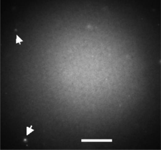
Fluorescence image of a POPC/NBD-PC bilayer formed on an ATRP polyacrylamide-modified fused silica surface. The arrows point to unfused lipid vesicles either in solution (diffusing rapidly) or attached to the surface (diffusing slowly). Excitation is with a mercury lamp. The scale bar is 70 μm.
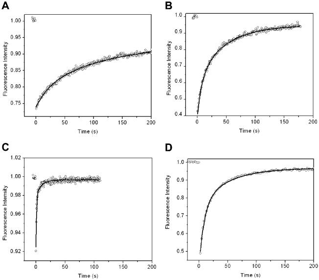
Fluorescence recovery after photobleaching (FRAP) was used to determine the diffusion coefficients of the NBD-PC lipid within the POPC bilayers. Figure 2 shows the FRAP recovery curves for NBD-PC in POPC bilayers for each of the four supports. Table 1 summarizes the fluorescence recovery parameters recovered from the analysis of the FRAP recovery curves, including diffusion coefficients and percent recovery. The diffusion coefficients were determined to be independent of the photobleached area (i.e., the same values are measured using a 10× or 20× microscope objective). For all surfaces, the data fit better to a double-exponential rather than a single-exponential recovery, as shown in Table 1 by the ratio of χ2 values. The two components of the exponential were equal within the error of the fit. It is presumed that the two diffusion coefficients correspond to NBD probes in the inner and outer leaflets of the bilayer.
Figure 2.
Plot of fluorescence recovery after photobleaching data from fluorescent probes in a lipid bilayer for four supports: (A) bare silica, (B) 2.5-nm polyacrylamide, (C) 5-nm polyacrylamide, and (D) 10-nm polyacrylamide. The solid curve is the best fit to a double-exponential recovery.
Table 1.
Recovery of Photobleaching, Diffusion Coefficients (D1, D2)a for POPC/NBD-PC Lipid Bilayers for Unmodified Fused Silica, ATRP Polyacrylamide-Modified Fused Silica Surfaces, Normalized χ2 Values for the Best Fit Parameters for FRAP Data to Double and Single Exponentials,b and the Mobility of hDOR in a POPC/NBD-PC Bilayer in the Presence of an Applied Electric Field
| surface | recovery (%) | D1 (lipid) cm2/s | D2 (lipid) cm2/s | χ2d/χ2s | mobility (protein) cm2/V·s |
|---|---|---|---|---|---|
| bare silica | 93 ± 3 | 2.0 ± (0.5) × 10–8 | 8.9 ± (0.3) × 10–8 | 0.74 | negligible |
| 2.5-nm PAAM | 93 ± 4 | 1.3 ± (0.7) × 10–8 | 1.8 ± (1.3) × 10–7 | 0.63 | negligible |
| 5-nm PAAM | 99 ± 1 | 2.0 ± (1.2) × 10–7 | 1.2 ± (0.5) × 10–6 | 0.64 | 3 × 10⁻⁸ |
| 10-nm PAAM | 97 ± 1 | 2.8 ± (1.2) × 10–8 | 1.4 ± (0.3) × 10–7 | 0.70 | 2 × 10⁻¹⁰ |
D1 and D2 are slower and faster diffusion coefficients, respectively.
The ratio χ2d/χ2s is the ratio of χ2 values from the single- and double-exponential fits to the recovery data. The error bars represent 95% confidence limits obtained from three replicate measurements.
The diffusion coefficients and percent recovery are nearly identical for the fused silica and 2.5-nm polymer layers as supports. This indicates that the 2.5-nm thickness provides little decoupling from the surface. The diffusion coefficients reported here for the bare silica, as well as the percent recovery, are higher than those for bare glass, reported previously.22
Comparing the two thicker polymer surfaces, one can see that Figure 2 illustrates that the rate of recovery for the case of 5 nm is obviously much greater than for the 10 nm polymer layer, indicating that there is an optimum in polymer thickness for maximizing lateral transport. The percent recovery is also higher for the 5-nm polymer support, approaching 100%. One might reasonably expect that the thicker the polymer, the faster the diffusion because of better decoupling, perhaps with eventual leveling off as thickness becomes sufficient. Why the lipid diffusion slows with polymer thickness is not at first obvious. A plausible explanation is that the progressively increasing roughness with polymer thickness slows the diffusion. The 10-nm polyacrylamide layer was made using twice the concentration of acrylamide monomer as was used to make the 5-nm layer. The solution becomes viscous during the reaction, indicating that radical transfer to monomers as a mode of termination is significant. The 10-nm layer is thus expected to be rougher than the 5-nm layer because of the greater amount of termination. It is possible that there are submicroscopic regions of roughness in the lipid bilayer that impede diffusion. The 5-nm thickness appears to be a compromise between the decreased coupling of the substrate and the increased surface roughness of the polymer. All of the diffusion coefficients are lower than those for NBD-PC (1-oleoyl-2-hexanoyl-NBD-phosphatidylcholine) in lecithin vesicles at 25 °C, which is 6.6 × 10⁻⁶ cm2/s.35 Although these are different lipids, the diffusion coefficients are sufficiently different from those of the lipid bilayers that this suggests that there is considerable interaction between the bilayer and its support layer in every case. The 5-nm support results in diffusion coefficients of 2.0 × 10⁻⁷ and 1.2 × 10⁻⁶ cm2/s, which leaves room for an estimated 1 order of magnitude improvement in the lateral transport of supported lipid bilayers.
B. Incorporation of a Functional Membrane Receptor into ATRP Polyacrylamide Films. A sample of the membrane protein human delta-opioid receptor (hDOR)36 was incorporated into each of the POPC bilayers by dilution of the detergent concentration below the critical micelle concentration. This method has previously been used to show that the receptor is functional, with respect to the binding of known ligands, for lipid bilayers formed across apertures.32 To determine whether the receptors are functional in these bilayers, single-molecule fluorescence was used to monitor the binding of a known ligand to hDOR, cyclic[2-d-penicillamine, 5-d-penicillamine]enkephalin,31 or
DPDPE. This ligand was chosen because it is a known agonist for this receptor. When the lipid bilayer with incorporated hDOR was exposed to a 5 nM solution of the labeled DPDPE, occasional bright fluorescent spots became visible in the beam diameter of 10 μm, as illustrated by the typical image shown in Figure 3. These bright spots typically remained bright on the time scale of a minute. These long-lived spots are interpreted to be ligands bound to receptors because this time scale is orders of magnitude longer than that for the small ligands diffusing out of the beam. There are also several dim spots evident in the image, and these were transient binding events lasting no longer than the 2 s acquisition time.
Figure 3.
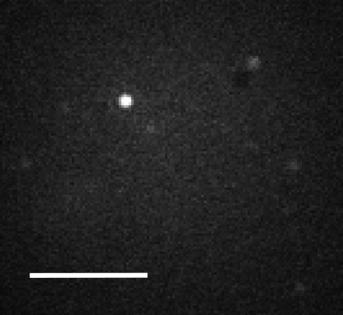
Single-molecule fluorescence image of single human delta-opioid receptors (hDOR) in a POPC bilayer on a 5-nm polyacrylamide-modified fused silica surface after exposure to 5 nM labeled DPDPE. The acquisition time was 2 s. The scale bar is 5 μm.
The receptors were well separated on the molecular scale; they are apart from one another on the optical scale. At such extreme dilution, clusters of receptors are highly unlikely. No spots were visible when the bilayer was exposed to the labeled DPDPE in the absence of the receptor. No spots were visible when rhodamine dye was used, rather than labeled DPDPE, in the presence of the receptor. A separate, two-color experiment monitoring the NBD lipid probe and the labeled DPDPE confirmed that the fluorescent spots attributed to receptors did not occur at positions where there were unfused vesicles.
A high concentration of labeled DPDPE, 1 μM, was added to saturate the receptors. The dissociation constant for the binding of unlabeled DPDPE to hDOR in the absence of G protein is 20 nM.32 To enable detection by fluorescence spectroscopy, the DPDPE was labeled at the N terminus with tetramethylrhodamine isothiocyanate. The effect of this labeling on the binding constant of the ligand is unknown. Figure 4A shows how the fluorescence (red) behaves as a function of time for a typical receptor at the saturating concentration of labeled DPDPE. The signal from a nearby pixel that does not have an active receptor is shown in black to indicate the background for comparison. The fluorescence from the receptor remains high most of the time, consistent with the concentration achieving receptor saturation. The data show that the fluorescence periodically drops, and when it does so, these drops often occur in clusters (e.g., 60, 80, and 155 s). The background often rises as the fluorescence from the receptor drops, suggesting that the ligand has become mobile and has briefly diffused through the region being used as the background. The images in Figure 4B bear out this interpretation. This series of images, beginning at 155 and progressing at 0.2 s/frame, demonstrates that when the fluorescence drops the ligand indeed diffuses from the receptor to illuminate the nearby pixels. The images show that this ligand, or another, then binds at the end of the sequence of images. Because a desorbed ligand randomly walks, the nearby pixel will not always be illuminated, and Figure 4A shows that there are events where the background does not rise when the signal falls, as expected. The fact that ligand desorption occur in clusters suggests that there are many weak binding events for every strong binding event. A third feature evident in the graph is that, while bound, the fluorescence intensity of the ligand wavers over time. For example, from 100 to 110 s, the fluorescence goes up to a somewhat higher level and then moves back down after another 10 s. This is possibly due to reorientation of the rhodamine label due to either multiple binding states or protein conformational changes. This study of the high concentration of labeled DPDPE shows that there is negligible single-molecule blinking on the time scale of the experiment. The data also suggest that photobleaching is not a problem at the low laser intensity used in this work.
Figure 4.
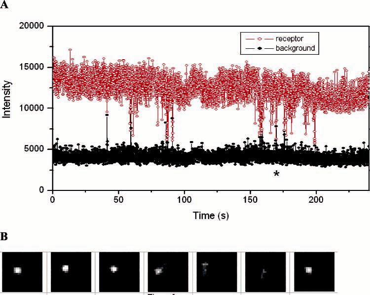
(A) Fluorescence vs time for single ligands in dynamic equilibrium with a receptor (red) and the background from a nearby pixel (black) for a saturating concentration of ligand, 1 μM. (B) Sequence of images showing the event indicated by the asterisk in part A.
To observe discrete on/off binding events of the ligand to the receptor, the concentration of ligand was lowered to 5 nM, which is well below the 20 nM dissociation constant of the unlabeled DPDPE. As expected, at this lower concentration of labeled DPDPE, the receptors flickered on and off, and most of the time the receptor was not occupied by a ligand. Figure 5 shows a plot of fluorescence versus time for one receptor at this lower concentration, for which the acquisition time had been increased from 0.2 to 2 s to increase S/N. There are two transient binding events, at 120 and 495 s, consistent with the interpretation that many binding events are transient, and there is one stable binding event, in this case lasting for 1 min. During this stable event, the fluorescence changed between two levels, in agreement with the behavior indicated in Figure 4A. Many events were studied, and the occurrence of many transient binding events and intensity changes during long binding events are typical. A histogram of binding times is provided in Figure 6, showing that the short events are the most abundant and occasional long binding events extend out to the scale of minutes. Overall, the study of low concentration bears out the interpretation of the data at high concentration that hDOR has been incorporated into the bilayer formed on ATRP polyacrylamide films and that this receptor binds known ligands in an expected manner. The data of Figure 4A indicate that 1 μM is a suitable concentration for monitoring single receptors.
Figure 5.
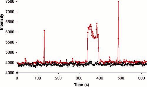
Fluorescence vs time for single ligands in dynamic equilibrium with a receptor (red) and the background from a nearby pixel (black) for a low ligand concentration, 5 nM.
Figure 6.
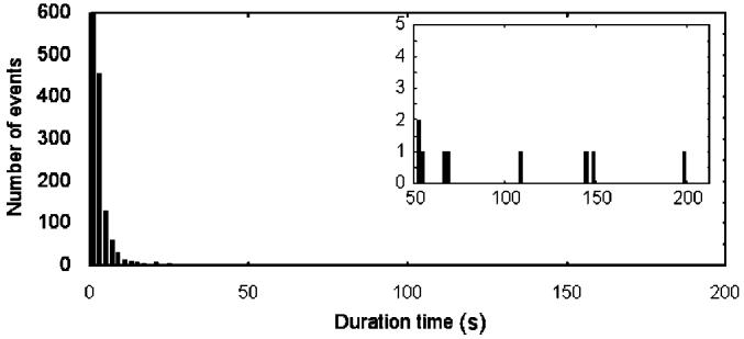
Histogram of the durations of single-molecule binding events for rhodamine-labeled DPDPE at individual delta-opioid receptors in the supported lipid bilayer. The inset shows an expanded scale for the longer binding events.
C. Measurement of the Electrophoretic Mobility of a Membrane Receptor in ATRP Polyacrylamide Films. The electrophoretic mobility of hDOR incorporated into the POPC bilayers was investigated by acquiring fluorescence images while an electric field was applied in the presence of a 1 μM concentration of rhodamine-labeled DPDPE to test the feasibility of 2D electrophoretic separations of membrane proteins within the bilayer. Using neutral lipid molecules and a neutral polymer cushion ensures that the lipid bilayer itself does not move in the electric field. The hDOR has a charge of -3 on its extracellular side; therefore, the receptor is expected to migrate in the electric field toward the anode if it is mobile. The receptor motion can be viewed by fluorescence spectroscopy when the fluorescent ligand is bound, and the binding of the ligand would impart an additional charge of -1. Figure 7 illustrates the movement of hDOR in an applied electric field, where positive voltage is to the right of the images. Figure 7A was taken at the start of the experiment, and Figure 7B was taken after applying an electric field of 1000 V/cm for 2.6 s. The orange line guides the eye to the starting point of the receptor. It is seen that the receptor moves toward the positive electrode, as expected on the basis of its charge. The mobility was measured quantitatively by monitoring the migration distance after 2 min in the applied field of 1000 V/cm for the receptor in each bilayer support. Table 1 lists the hDOR mobilities for the lipid bilayers supported on bare fused silica, 2.5-, 5-, and 10-nm-thick polyacrylamide films. The current was not monitored, so it is possible that the low resistance of the buffer layer loaded the power supply, which would cause an underestimation of the mobilities. The receptor did not move after 20 min of observation for either the bare fused silica or the 2.5-nm polyacrylamide as a support for the bilayer. This is interpreted to be due strong coupling between the receptor and the solid surface. The intracellular peptide loops of the receptor extend to a distance on the order of 2.5 nm,37 necessitating a polymer layer exceeding this thickness. The mobility of the receptors was nonzero in the bilayers supported by the 5- and 10-nm polyacrylamide layers. The mobility is 100-fold faster for the 5-nm polyacrylamide support. Because the lipid probe diffuses 10-fold faster for the 5-nm polyacrylamide film, the factors affecting the lipid diffusion so strongly are presumed to affect the receptor migration even more. The 5-nm polyacrylamide support is optimal for those films studied with respect to the electromigration of the receptor, and fine tuning of the polymer thickness could provide higher mobility. The reproducibility for different preparations of material was not investigated.
Figure 7.
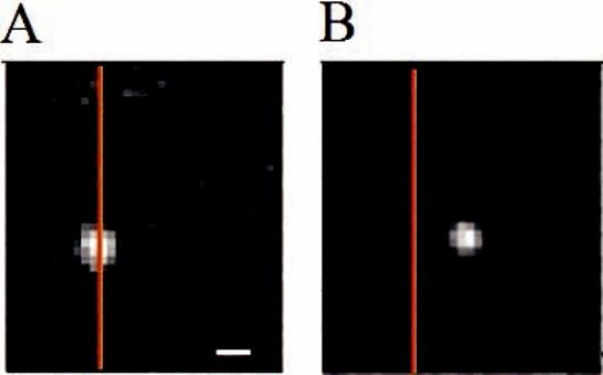
Fluorescence images of a single receptor migrating in an applied electric field of 1000 V/cm. Images were taken (A) before applying an electric field and (B) after applying the electric field for 2.3 s. hDOR is in a POPC bilayer supported on a 5-nm-thick polyacrylamide layer on fused silica. The scale bar is 400 nm, and the orange line is a guide to the position of the receptor at the beginning of the applied field.
The electrophoretic mobility of 10-8 V/cm△s for the receptor is encouraging in that this is, to our knowledge, the first time a transmembrane protein has been shown to be laterally mobile in a lipid bilayer in an applied electric field. At the same time, it must be pointed out that the mobility needs to be increased by at least an order of magnitude for electrophoresis within these bilayers to be practical for transmembrane proteins. The basis for this estimate is that a 10-fold-higher mobility, which would be 10-7 cm2/V△s, would allow hDOR to electromigrate 10 cm in 10 h for an applied field of 1000 V/cm. Overnight runs are common in gel electrophoresis, a 10-cm separation length is quite substantial, and a 1000 V/cm field is reasonable given that a thin medium can be constructed to dissipate Joule heat well. Understanding the factors that control the mobilities of transmembrane proteins would greatly assist in the design of a support that enhances electrophoretic mobility, and the results point to interfacial roughness as one significant factor.
Conclusions
The results show that atom-transfer radical polymerization enables the formation of uniform lipid bilayers on polyacrylamide brush layers, grown by ATRP, without the need for electrostatic attractions, and this is attributed to the unusual smoothness of these polymer layers. The hDOR receptor, a transmembrane protein, is mobile in the lipid bilayers when the polymer support is sufficiently thick to decouple the bilayer from the substrate, which is reached between 2.5 and 5 nm in thickness. The results indicate that sufficient polymer thickness is not the only factor in controlling the mobility of either the lipids in the bilayer or the transmembrane protein. Because thicker polymers are presumed to have rougher surfaces because of their necessarily higher polydispersity, the results indicate that at 10-nm thickness the polymer has already become too rough. The results also show that the mobility of the transmembrane protein is much more sensitive to polymer thickness than the lipid diffusion coefficient. This suggests that small improvements in polymer smoothness might provide large improvements in protein mobility. New approaches to preparing smoother polymer films, such as smoother substrates and fewer termination reactions, are worthwhile approaches to enable electrophoresis of transmembrane proteins in neutral supported lipid bilayers.
Acknowledgment
This work was supported by the Department of Energy, grant DE-FG02-04ER15596 (M.J.W.), the National Science Foundation, grant CHE: 0433779 (M.J.W.) and the U.S. Public Health Service, grant DA 06284 (V.J.H.).
References
- 1.Devadoss A, Burgess JD. J. Am. Chem. Soc. 2004;126:10214–10215. doi: 10.1021/ja047856e. [DOI] [PubMed] [Google Scholar]
- 2.Holden MA, Jung S-Y, Yang T, Castellana ET, Cremer PS. J. Am. Chem. Soc. 2004;126:6512–6513. doi: 10.1021/ja048504a. [DOI] [PubMed] [Google Scholar]
- 3.Kung LA, Kam L, Hovis JS, Boxer SG. Langmuir. 2000;16:6773–6776. [Google Scholar]
- 4.Shaw JE, Slade A, Yip CM. J. Am. Chem. Soc. 2003;125:11838–11839. doi: 10.1021/ja0370894. [DOI] [PubMed] [Google Scholar]
- 5.Kam L, Boxer SG. J. Biomed. Mater. Res. 2001;55:487–495. doi: 10.1002/1097-4636(20010615)55:4<487::aid-jbm1041>3.0.co;2-7. [DOI] [PubMed] [Google Scholar]
- 6.Klughammer B, Benz R, Betz M, Thume M, Dietz K-J. Biochim. Biophys. Acta. 1992;1104:308–316. doi: 10.1016/0005-2736(92)90045-n. [DOI] [PubMed] [Google Scholar]
- 7.Lagerholm BC, Starr TE, Volovyk ZN, Thompson NL. Biochemistry. 2000;39:2042–2051. doi: 10.1021/bi9917434. [DOI] [PubMed] [Google Scholar]
- 8.Goennenwein S, Tanaka M, Hu B, Moroder L, Sackmann E. Biophys. J. 2003;85:646–655. doi: 10.1016/S0006-3495(03)74508-1. [DOI] [PMC free article] [PubMed] [Google Scholar]
- 9.Giocondi M-C, Le Grimellec C. Biophys. J. 2004;86:2218–2230. doi: 10.1016/S0006-3495(04)74280-0. [DOI] [PMC free article] [PubMed] [Google Scholar]
- 10.Leonenko ZV, Carnini A, Cramb DT. Biochim. Biophys. Acta. 2000;1509:131–147. doi: 10.1016/s0005-2736(00)00288-1. [DOI] [PubMed] [Google Scholar]
- 11.Keller CA, Kasemo B. Biophys. J. 1998;75:1397–1402. doi: 10.1016/S0006-3495(98)74057-3. [DOI] [PMC free article] [PubMed] [Google Scholar]
- 12.Tollin G, Salamon Z, Hruby VJ. Trends Pharmacol. Sci. 2003;24:655–659. doi: 10.1016/j.tips.2003.10.010. [DOI] [PubMed] [Google Scholar]
- 13.Cremer PS, Boxer SG. J. Phys. Chem. B. 1999;103:2554–2559. [Google Scholar]
- 14.Schmitt J, Danner B, Bayer TM. Langmuir. 2001;17:244–246. [Google Scholar]
- 15.Starr TE, Thompson NL. Langmuir. 2000;16:10301–10308. [Google Scholar]
- 16.Theato P, Zentel R. Langmuir. 2000;16:1801–1805. [Google Scholar]
- 17.Williams LM, Evans SD, Flynn TM, Marsh A, Knowles PF, Bushby RJ, Boden N. Langmuir. 1997;13:751–757. [Google Scholar]
- 18.Wong JY, Park CK, Seitz M, Israelachvili JN. Biophys. J. 1999;77:1458–1568. doi: 10.1016/S0006-3495(99)76993-6. [DOI] [PMC free article] [PubMed] [Google Scholar]
- 19.Feng ZV, Granick S, Gewirth AA. Langmuir. 2004;20:8796–8804. doi: 10.1021/la049030w. [DOI] [PubMed] [Google Scholar]
- 20.Xie AF, Yamada R, Gewirth AA, Granick S. Phys. Rev. Lett. 2002;89:246103. doi: 10.1103/PhysRevLett.89.246103. [DOI] [PubMed] [Google Scholar]
- 21.Koenig BW, Krueger S, Orts WJ, Majkrzak CF, Berk NF, Silverton JV, Gawrisch K. Langmuir. 1996;12:1343–1350. [Google Scholar]
- 22.Brian AA, McConnell HM. Proc. Natl. Acad. Sci. U.S.A. 1984;81:6159–6163. doi: 10.1073/pnas.81.19.6159. [DOI] [PMC free article] [PubMed] [Google Scholar]
- 23.Shen WW, Boxer SG, Knoll W, Frank CW. Biomacromolecules. 2001;2:70–79. doi: 10.1021/bm005581z. [DOI] [PubMed] [Google Scholar]
- 24.Munro JC, Frank CW. Langmuir. 2004;20:10567–10575. doi: 10.1021/la048378o. [DOI] [PubMed] [Google Scholar]
- 25.Richter RP, Brisson A. Langmuir. 2003;19:1632–1640. [Google Scholar]
- 26.Huang X, Doneski LJ, Wirth MJ. Anal. Chem. 1998;70:4023–4029. doi: 10.1021/ac980231c. [DOI] [PubMed] [Google Scholar]
- 27.Xiao D, Wirth MJ. Macromolecules. 2002;35:2919–2925. [Google Scholar]
- 28.Xiao D, Zhang H, Wirth MJ. Langmuir. 2002;18:9971–9976. [Google Scholar]
- 29.Axelrod D, Koppel DE, Schlessinger J, Elson E, Webb WW. Biophys. J. 1976;16:1055–1067. doi: 10.1016/S0006-3495(76)85755-4. [DOI] [PMC free article] [PubMed] [Google Scholar]
- 30.Koppel DE, Axelrod D, Schlessinger J, Elson E, Webb WW. Biophys. J. 1976;16:1315–1329. doi: 10.1016/S0006-3495(76)85776-1. [DOI] [PMC free article] [PubMed] [Google Scholar]
- 31.Mosberg HI, Hurst R, Hruby VJ, Gee K, Yamamura HI, Galligan JJ, Burks TF. Proc. Natl. Acad. Sci. U.S.A. 1983;80:5871–5874. doi: 10.1073/pnas.80.19.5871. [DOI] [PMC free article] [PubMed] [Google Scholar]
- 32.Alves ID, Salamon Z, Varga E, Yamamura HI, Tollin G, Hruby VJ. J. Biol. Chem. 2003;278:48890–48897. doi: 10.1074/jbc.M306866200. [DOI] [PubMed] [Google Scholar]
- 33.Keller CA, Glasmastar K, Zhdanov VP, Kasemo B. Phys. Rev. Lett. 2000;84:5443–5446. doi: 10.1103/PhysRevLett.84.5443. [DOI] [PubMed] [Google Scholar]
- 34.Huang MX, Vorkink WP, Lee ML. J. Microcolumn Sep. 1992;4:233–238. [Google Scholar]
- 35.Prieto MJE, Castanho M, Coutinho A, Ortiz A, Aranda FJ, Gomez-Fernandez JC. Chem. Phys. Lipids. 1994;69:75–85. doi: 10.1016/0009-3084(94)90029-9. [DOI] [PubMed] [Google Scholar]
- 36.Quock RM, Burkey TH, Varga E, Hosohata Y, Hosohata K, Cowell S, Slate CA, Ehlert FJ, Roeske WR, Yamamura HI. Pharmacol. Rev. 1999;51:503–532. [PubMed] [Google Scholar]
- 37.Aburi M, Smith PE. Protein Sci. 2004;13:1997–2008. doi: 10.1110/ps.04720304. [DOI] [PMC free article] [PubMed] [Google Scholar]


