Abstract
The centroid of a fluorophore can be determined within ≈1.5-nm accuracy from its focused image through fluorescence imaging with one-nanometer accuracy (FIONA). If, instead, the sample is moved away from the focus, the point-spread-function depends on both the position and 3D orientation of the fluorophore, which can be calculated by defocused orientation and position imaging (DOPI). DOPI does not always yield position accurately, but it is possible to switch back and forth between focused and defocused imaging, thereby getting the centroid and the orientation with precision. We have measured the 3D orientation and stepping behavior of single bifunctional rhodamine probes attached to one of the calmodulins of the light-chain domain (LCD) of myosin V as myosin V moves along actin. Concomitant with large and small steps, the LCD rotates and then dwells in the leading and trailing position, respectively. The probe angle relative to the barbed end of the actin (β) averaged 128° while the LCD was in the leading state and 57° in the trailing state. The angular difference of 71° represents rotation of LCD around the bound motor domain and is consistent with a 37-nm forward step size of myosin V. When β changes, the probe rotates ±27° azimuthally around actin and then rotates back again on the next step. Our results remove degeneracy in angles and the appearance of nontilting lever arms that were reported.
Keywords: 3D orientation, lever arm, single molecule, fluorescence imaging with one-nanometer accuracy
Complementary conformational changes can be measured on single motor proteins by use of fluorescence imaging with one-nanometer accuracy (FIONA) (1–3) and by single-molecule fluorescence polarization microscopy (SMFP) (4). FIONA is a method in which the emission distribution of a single fluorophore is detected by using a charge-coupled device and fitted to a 2D Gaussian function to determine the position of the probe. The positional accuracy of the measurement, typically ≈1.5 nm, is generally limited by the number of collected photons (1–3). In contrast, SMFP is sensitive to the 3D orientation of a single dye’s transition dipole moments (4). In SMFP, the dye is excited by multiple polarized beams, incident from different directions. The resulting emission is split with respect to its polarization and detected with avalanche photodiodes (APDs). However, by slightly defocusing the microscope objective and by using appropriate fitting routines, the defocused image of the probe can be used to determine both its position and its orientation (5–7). We call this technique defocused orientation and position imaging (DOPI). When the sample is deliberately moved ≈500 nm away from the best focus position, combinations of lobes and fringes appear on the charge-coupled device. These images are compared with calculated model images to obtain the best estimates of both 3D orientation and position of the probe. Because the image is spread out over a greater number of pixels in DOPI versus FIONA, DOPI inherently has poorer signal-to-noise ratio for positional measurements. For this reason, it is sometimes advantageous to switch back and forth between focused (i.e., FIONA) and defocused imaging, thereby getting the position and the orientation with better accuracy.
We first show the ability to determine 3D orientation of dipolar quantum dots (8). We then perform both DOPI and combined FIONA/DOPI on myosin V with one of its calmodulin (CaM) light chains labeled with a bisiodoacetamidorhodamine (BR). Several previously undescribed features about the lever arm dynamics and translocation of myosin V were revealed.
Results and Discussion
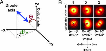
By using DOPI, we are able to detect 3D orientations of quantum dots that have linear emission dipoles (8), as well as conventional fluorophores (9). Here we move the sample ≈500 nm away from best focus position and use a pattern-match analysis technique to detect position and orientation of the probe (10). When the emission dipole of the quantum dot is oriented along the z axis (Θ = 0, which is the angle between dipole axis and optical axis; Fig. 1B), a donut pattern appears (Fig. 1B Left). When oriented in the x-y plane, a symmetric pattern appears with the dipole axis (parallel to the dark line between two symmetric bright lobes in Fig. 1B Right) making an angle of Φ = 138° with the +x axis. An emission dipole at an arbitrary (x, y, z) plane is a combination of the two images (Fig. 1B Center). The accuracy of measuring these quantities is closely related to the number of collected photons. The angles can be measured for conventional fluorophores with an uncertainty of 10–15° in 0.6 s. With quantum dots, which are brighter and have better photostability than conventional organic dyes, DOPI yields ≈5-fold better temporal resolution. In addition, DOPI has no angular degeneracy in terms of detecting the emission dipole axis of a fluorophore other than dipolar degeneracy (for the angular accuracy of DOPI and the effect of the dipolar degeneracy, see Supporting Text, which is published as supporting information on the PNAS web site) (4, 11).
Fig. 1.
Right-handed spherical coordinate system and sample defocused patterns in DOPI. (A) Right-handed spherical coordinate system where the z axis is the optical axis, Θ is the axial angle relative to the z axis (0 ≤ Θ ≤ 90°), and Φ is the azimuthal angle around the z axis (0 ≤ Φ ≤ 360°). Note that a dipole always has an inherent degeneracy regardless of the detection method, i.e., (Θ, Φ) is equivalent to (180° − Θ, Φ − 180°). (B) Defocused images of quantum dots (frozen in 1% polyvinyl alcohol) showing examples of vertical, inclined, and parallel emission dipoles (Upper) and corresponding theoretical calculated patterns (Lower). The observed pattern is donut shaped when the emission dipole is along the z axis, i.e., perpendicular to the sample plane (Θ = 0°). It has two lobes when the emission dipole is in the x-y plane, i.e., parallel to the sample plane (Θ = 90°). The pattern is a combination of a donut and two lobes if the emission dipole is inclined. The dark line between the two lobes can be tracked to visualize the in-plane angle (Φ is opposite to the dark region when the objective is moved away from the sample in an inverted microscope).
Next, we focused on myosin V, a dimeric motor protein in cells that transports cargo processively along actin in a hand-over-hand fashion (1, 12). Each half of the dimeric myosin V is formed by a motor domain (MD), which also binds actin and hydolyzes ATP to swing a light-chain domain (LCD) forward (13). Myosin V follows a slightly left-handed helical pathway around actin when the motility path is not constrained by the surface underneath the actin filament, completing a helical rotation every 2.2 μm (14), and the average step size is proportional to the length of the LCD (15, 16).
We switched between an in-focus image, i.e., FIONA, to get the centroid very accurately, and DOPI, to get the angles while myosin V molecules walked along the actin in the presence of ≈300 nM ATP. In total, 32 molecules were observed with alternating focused and defocused imaging. These combined measurements were generally more accurate for measuring the centroid than were pure DOPI measurements. Nevertheless, we also used DOPI exclusively to get the angles and the lateral position of the fluorophore (see later in text and Fig. 4B).
Fig. 4.
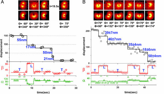
Displacement and 3D orientation trajectories of two different myosin V molecules, showing ≈53–19 nm and ≈44–32 nm stepping. (A) A sample trace of a myosin V molecule that was imaged by switching between focused and defocused imaging. The exposure time is 0.75 s, and we have captured cycles of consecutive four defocused images and two focused images. For the step at t = 19.5 s, the image of BR is focused; therefore, the position is available, but not the orientation. The position information at t = 9.75 s is not shown because the image was shifting due to defocused-to-focused imaging. The sample is moved away from the focus by 500 nm. Φactin = 0°. (B) A sample trace of a myosin V molecule that was imaged by pure defocused imaging (DOPI). The exposure time is 0.75 s, and the sample is moved away from focus by 500 nm. Φactin = 24°.
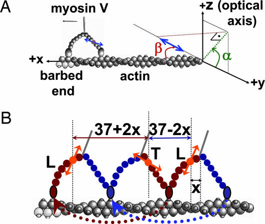
We labeled CaM with a single BR that was attached to two cysteine residues at positions 66 and 73 and exchanged onto the LCD of myosin V (4). We measure the 3D orientation of the dipole axis in a laboratory spherical coordinate frame (Θ, Φ; Fig. 1A) and subsequently transformed the angles into an actin-based coordinate system (α, β) for the moving myosin V molecules. Here β is the axial probe angle with respect to the actin, and α is the azimuthal angle around actin (see Fig. 2A; see also Movies 1 and 2 and Figs. 7 and 8, which are published as supporting information on the PNAS web site). Because the myosin V is labeled on one of the light chains, the step sizes alternate between short and long steps (Fig. 2B) (1). For example, if the dye is on the leading lever arm, and the myosin V takes a step, the displacement of the fluorophore is a relatively short 37 − 2x nm, where x is the in-plane distance of the dye from the midpoint of myosin. (That is, x is the distance from the stalk, assuming there is sufficient symmetry.) The following step will show a larger displacement, 37 + 2x nm. To identify the LCD angle obtained after the larger and smaller values corresponding to the leading and trailing states, we combined FIONA and DOPI.
Fig. 2.
The actin-based coordinate system and the relative orientation of actin, myosin V, and dye. (A) The actin-based coordinate system that is necessary to interpret myosin V motions. For example, tilting of the lever arm because of the power stroke is observed as an azimuthal rotation around the optical axis (change in Φ) when myosin is on the side of the actin and as a rotation relative to the optical axis (Θ) when the myosin V is on top of the actin. In the actin-based coordinate system in which α (0 ≤ α ≤ 180°) is the azimuthal angle around actin axis, and β (0 ≤ β ≤ 180°) is the axial angle around the actin axis, these motions correspond to changes in β if the molecule is on the top or side of actin. (B) Cartoon diagram of two consecutive steps of myosin V walking toward the barbed end of actin for which x is the distance between the BR and the midpoint of the MDs. Thus, the sizes for consecutive steps are 37 − 2x and 37 + 2x. The lever arm is in the leading state after a long step of 37 + 2x nm (shown with red double-headed arrow) and is in the trailing state after a short step of 37 − 2x nm (shown with blue double-headed arrow). The orange double arrows show the emission dipole of the BR. The angle between the dipole axis and barbed end of actin (β) is expected to take on smaller values after short steps and larger values after long steps.
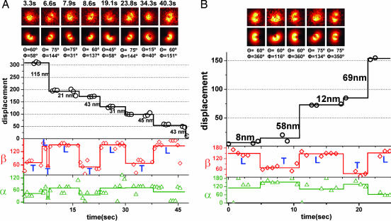
Fig. 3A shows a sample trace obtained from focused and defocused images that show ≈30- to 44-nm alternating sized steps (see the molecule at the center of the screen in Movie 3, which is published as supporting information on the PNAS web site). The first step in the FIONA trace is ≈115 nm (black curve). This step includes two hidden steps that can be tracked from β changes (red curve). During this period the LCD goes through three transitions (trailing → leading → trailing → leading) that will generate two long steps and a short step (2 × 44 nm + 30 nm = 118 nm ≈ 15 nm). After this step, β switches from ≈53° to ≈150° in going from the trailing position to the leading position. The following step sizes in Fig. 3A are alternating short steps (≈30 nm) and long steps (≈44 nm). When going from the trailing LCD to the leading LCD, on average β changes from 60° to 148°. The azimuthal angle, α, changes during the first step shown in Fig. 3A from 43° to 61°.
Fig. 3.
Displacement and 3D orientation of two different myosin V molecules showing ≈44–30 nm and ≈64–10 nm stepping. (A) A sample trace of a myosin V molecule that was imaged by switching between focused and defocused imaging. The exposure time per frame is 0.66 s. We have captured repeated cycles of five consecutive defocused images and three focused images. The sample is moved away from the best focus by 500 nm. Black circles, raw position data analyzed by FIONA; black lines, averaged position within each dwelling period; red diamonds, raw β values analyzed by DOPI; red lines, dwell-averaged β values; green triangles, raw α values; green lines, dwell-averaged α values. The patterns above the graph are representative defocused images for each dwell time and the corresponding theoretically calculated patterns. Φactin = 340°. (B) A sample trace of a myosin V molecule, imaged by switching between focused and defocused imaging. The exposure time is 0.75 s, and we have captured cycles of consecutive four defocused images and two focused images. Note that angular data points at t = 18.75 s are not shown because the image was in a transition stage from focused to defocused image. The sample is moved away from the focus by 500 nm. Φactin = 180°.
Because of the dipolar degeneracy, there is another set of possible averaged (α, β) angles, (α − 180°, 180° − β) = (−138°, 120°) for the trailing LCD and (−117°, 32°) for the leading LCD, respectively. The negative α values imply the myosin V molecule occupying the space in the angular hemisphere underneath the actin filament. However, because of restriction of the space between the actin and the glass slide by the biotin–streptavidin linkages, we expect most of the molecules to walk along the top face of the actin, away from the glass. For most of the molecules analyzed in the present study (94 of 97 molecules), restricting the angular range of the probes to the upper hemisphere, e.g., 0 < β < 180° and 0 < α < 180°, resulted in the probe angle β, relative to the barbed end of actin, being greater for the leading head (after completing a large step) than for the trailing head (after a small step). Because the probe probably lies within ≈40° away from the LCD axis (4), the leading LCD is expected to adopt a larger angle relative to the barbed end of actin than the trailing LCD (17). If we adopt the opposite convention for converting the laboratory coordinate angles into the actin reference frame, then α becomes negative, implying that the myosin V molecules are between the actin and the glass, and the β angle is larger after the smaller FIONA step (trailing position) than after the larger step (leading position). The unlikely nature of both of these conditions implies that the bound state after the larger FIONA step and the larger β angle consistently identify the leading LCD. In a few of the molecules that swung very near to the x-y plane, a slight azimuthal tilt into the lower angular hemisphere was apparent, as explained in Supporting Text.
Fig. 3B shows a molecule that alternates between ≈64- and ≈10-nm step sizes (see the molecule at the center of the screen in Movie 4, which is published as supporting information on the PNAS web site). In our earlier work (1), this molecule would have been classified as taking 74- and 0-nm steps because we did not have either sufficient accuracy or the simultaneous angular information that we have here. These results indicate that myosin V does not have a sharp kink structure in the leading lever arm as previously proposed (18). The sharp kink, like the bent knee of a telemark skier (18), is ruled out because (i) an angular transition occurs for every step, as expected for a nonkinked lever arm (Fig. 2B), and (ii) unless the lever arm is kinked, long steps are expected to be followed by short steps (Fig. 2B), but not ≈0-nm steps. Notice that if the fluorophore is placed on the MD, e.g., with a green fluorescent protein (GFP), a 74- to 0-nm stepping pattern is expected, as indeed was observed (18). This result is consistent with a more detailed analysis that shows 64–10 nm (19). In Fig. 4A, we show a trace of ≈53–19 nm stepping pattern (see the molecule at the center of the screen in Movie 5, which is published as supporting information on the PNAS web site).
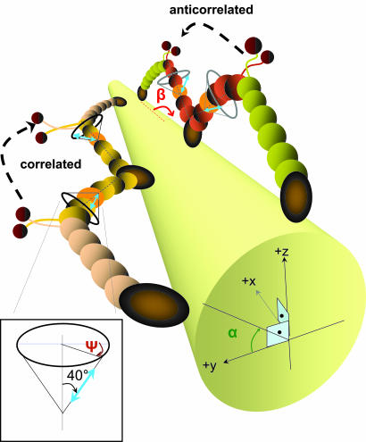
In Fig. 3B, when going from the trailing LCD to the leading LCD, β changes from ≈50° to 148°, a similar β change as in Fig. 3A. Notice that in this case and in Fig. 4A, the α and β angles are anticorrelated, meaning they change at the same time but in the opposite direction. Other molecules show correlated changes of α and β (e.g., Figs. 3A and 4B). The amplitude of back-and-forth sideways (α) motions averaged ≈27° (see Fig. 9 and Movie 6, which are published as supporting information on the PNAS web site). Approximately 35% of the molecules showed correlated α and β changes, ≈50% of molecules showed anticorrelated α and β changes, and in the rest of the molecules, the relationship between α and β changes was not clear. These correlated and anticorrelated α and β changes are likely to be caused by orientation of the fluorescent probe dipole out of the plane of LCD rotation. For instance, taking the probe to be oriented 40° away from the LCD axis (4), and the plane containing the LCD and the probe to be twisted or tilted by 32° relative to the plane containing the LCD and actin, the probe would exhibit the correlated changes of α and β shown in Fig. 3A. The azimuthal angle of the lever arm around the actin filament remains unchanged during this swinging. The estimated actin–LCD geometry for the molecules in Fig. 3 is shown in Fig. 5. If the plane containing the probe and the LCD is twisted or tilted by 51° in the opposite direction, then the probe would exhibit the anticorrelated changes of α and β shown in Fig. 3B. Such azimuthal variation among individual myosin V molecules is expected when their labeled CaM is on different IQ motifs (20). Note that in both of these cases, and in general, when the probe is not located in the plane of LCD tilting, the probe tilts less than the LCD. For instance in Fig. 3A, when the probe is 32° out of the LCD–actin plane, the LCD tilts from β = 122° to 15° when the probe tilts from the observed values of β = 150° to 53°, and αLCD = 17°. Although these calculations (4) show that the observed azimuthal rotations of the probe are not necessarily coming from the azimuthal rotations of the myosin V molecules, there may be other possible effects that might contribute to correlation or anticorrelation between β and α such as leaning of the molecules to the left and right on each step, twisting of LCD around its own axis, or interactions between myosin V and the glass.
Fig. 5.
Cartoon showing the estimated geometries of LCD–actin for the molecules in Fig. 3 A (correlated) and B (anticorrelated). The actin is represented by a cylinder, and the dipoles are shown in blue. The angle between the lever-arm axis and the dipole axis is ≈40°, and the azimuthal angle of the dipole axis around the lever-arm axis is variable for different CaM positions. Labeled light chains are shown in orange.
Fig. 4B shows simultaneous angular and displacement trajectories for a moving myosin V measured by pure DOPI analysis (see the molecule at the center of the screen in Movie 7, which is published as supporting information on the PNAS web site). The raw displacement data from DOPI by itself is usually not precise enough to detect alternating short and long steps because of the limited positional accuracy. However, the angular information (α and β) gives clear indications that steps occurred. The averaged step sizes are ≈44 nm for long steps and ≈32 nm for short steps for that particular molecule. Average β value for the trailing LCD is 68° and 131° for the leading LCD. The α value at the beginning of the plot is 18°, which indicates that the probe is very close to the glass surface. Although the molecule initially has small α changes, correlated with β changes, α increases by ≈20° after five steps. This α increase indicates that the molecule walked with a slight right-handed pitch moving from side to the top of the actin.
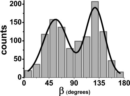
Fig. 6 shows the histogram of β for 97 myosin V molecules undergoing 1,151 tilting events, for all of the data from focused and defocused experiments and for the purely defocused data as well. All moving myosin Vs (n = 97) had lever arm tilts (see Movies 1 and 2), in contrast to the anomalous results previously seen (4). In the absence of ATP, none of the myosin V molecules (n = 30 molecules) showed rotations. For those subsets where we looked at myosin V by means of alternating defocused and focused imaging, all of the stepping events (n = 183 steps) and tilting events were found to be coincident with each other. The averaged β values for all moving molecules switch between β1 ≅ 57 ± 22° and β2 ≅128 ± 17° (means ± standard deviations). The standard deviations indicate that the β distributions for both of trailing and leading states of the LCD are quite broad, possibly because of differences in the CaM position on the LCD. The difference between the two β angles is 71°, which can be compared with a β difference of 45° in the previous measurement (4) considering the fourfold angular degeneracy of SMFP in that study. It should be mentioned that the degeneracy problem of SMFP can be removed by making additional polarization measurements (11) beyond those done on myosin V (4). The 71° rotation of the 24-nm LCD alone gives 28-nm translation [= 24 nm × (cos 57° − cos 128°)] along the actin per stroke. This 28-nm translation is an average calculation assuming that both of the lever arms are straight. However, either the curved structure of the leading lever arm or twisting of the labeled CaM around the axis of LCD may change the measured values for probe angles relative to the LCD position in the plane of the filament.
Fig. 6.
Histogram of the dwell-averaged β values for moving myosin V molecules in the presence of ≈300 nM ATP. A total of 1,151 tilting events are observed for 97 myosin V molecules, and the resulting histogram is fit into a two-peaked Gaussian function (r2 = 0.945). The peak with the lower value (β1 = 57°) corresponds to the trailing state, and the peak with the higher value (β2 = 128°) corresponds to the leading state. The standard deviation is 22° for β1 and 17° for β2.
In conclusion, by using DOPI-FIONA, we have ruled out reported nontilting myosin V molecules (4), as well as 74- to 0-nm steps (1). We observed myosin V primarily undergoing back-and-forth, ≈27° sideways motions. The axial probe angle difference in β between leading and trailing positions is 71°, consistent with the ≈75° tilting of the lever arm around actin measured by electron microscopy (21). A 71° rotation is compatible with a ≈36-nm center-of-mass translation of the stalk if rotation of the MD is significant or if the leading lever arm is curved or twisted. This previously undescribed method to capture dynamics of biological macromolecules is an application of defocused and focused imaging that measure both orientation and position of single fluorophores in a biological system.
Materials and Methods
Quantum Dots.
Q-dots (QS655) were purchased from Quantum Dot (Hayward, CA).
Proteins.
Myosin V was prepared from brains of newly hatched chickens, and labeled on one of its CaM light chains with BR, according to published procedures (4). Actin was purified from rabbit muscle according to a published protocols (22) modified by Murray et al. (23). Actin polymerization and biotinylation were performed following the protocol described by Sakamoto et al. (24).
Actin Immobilization.
M5BufBH (20 mM Hepes/2 mM MgCl2/25 mM KCl/1 mM EGTA, pH 7.6) was prepared weekly for all incubations and dilutions. Observation chambers were prepared by using a glass microscope slide and a coverslip (0.17-mm thickness) separated by double-sided adhesive tape to obtain a volume of ≈20 μl. Actin immobilization was done in three steps, with each step followed by washing with 100 μl of M5BufBH. Steps were as follows: (i) incubation with 50 μl of 0.67 mg/ml BSA–biotin (A-8549; Sigma) for 5 min; (ii) incubation with 50 μl of 0.5 mg/ml streptavidin (S-888; Molecular Probes) for 5 min; and (iii) incubation with 30 μl of 100 nM biotinylated F-actin (1 biotin/20 actin monomers) for 5 min.
In Vitro Motility Assay.
Thirty microliters of ≈2 pM BR-labeled myosin V molecules in M5BufBH++ (10 mM DTT and 0.1 mg/ml CaM in M5BufBH) was added to the immobilized actin in the absence of ATP. After the actin decorated with myosin V molecules was visualized, 30 μl of imaging buffer containing ≈300 nM ATP was added (imaging buffer is prepared freshly during actin immobilization process). One hundred microliters of imaging buffer contained 2 μl of 20% glucose solution in distilled water, 1 μl of 2-mercaptoethanol, 1 μl of gloxy, 10 μl of 10 mg/ml casein, 6 μl of 5 μM ATP, and 80 μl M5BufBH++ (pH 7.6). Gloxy was prepared weekly with 1,665 units of glucose oxidase (G-7016; Sigma) and 26,000 units of catalase (106810; Roche) in 0.2 ml of M5BufBH buffer, passed twice through 0.2-μm syringe filters, and centrifuged at 13,000 × g for 5 min.
Imaging.
Fluorophores were excited with a 532-nm diode-pumped Nd:YAG laser (CrystaLaser, Reno, NV) by using an objective type total internal reflection (TIR) microscope setup that included an IX-71 inverted microscope (Olympus, Melville, NY) with 1.6× magnification unit and an infinity corrected 100× objective (Olympus Planapo 100×/1.45 OIL) (1). DOPI is not sensitive to the polarization of the excitation illumination, but circularly polarized excitation light was used to reduce orientation-dependent fluctuations of fluorescence intensity. Images were captured by using a back-thinned charge-coupled device camera (512 × 512 pixels, 16 × 16-μm pixel size; Andor, South Windsor, CT). A piezoelectric z-axis sample stage (Nano-Z100; Mad City Labs, Madison, WI) was used to control the distance between the sample and objective. The image acquisition and defocusing were synchronized by using a custom C++ program.
Supplementary Material
Acknowledgments
We thank Roger E. Goldman for help with the angular coordinate transformations. This work was supported by National Institutes of Health Grants AR44420 and GM68625 (to P.R.S.) and AR26846 (to Y.E.G.). S.A.M. is a National Science Foundation graduate research fellow.
Abbreviations
- BR
bisiodoacetamidorhodamine
- CaM
calmodulin
- DOPI
defocused orientation and position imaging
- FIONA
fluorescence imaging with one-nanometer accuracy
- LCD
light-chain domain
- MD
motor domain
- SMFP
single-molecule fluorescence polarization microscopy.
Footnotes
Conflict of interest statement: No conflicts declared.
This paper was submitted directly (Track II) to the PNAS office.
References
- 1.Yildiz A., Forkey J. N., McKinney S. A., Ha T., Goldman Y. E., Selvin P. R. Science. 2003;300:2061–2065. doi: 10.1126/science.1084398. [DOI] [PubMed] [Google Scholar]
- 2.Yildiz A., Tomishige M., Vale R. D., Selvin P. R. Science. 2004;303:676–678. doi: 10.1126/science.1093753. [DOI] [PubMed] [Google Scholar]
- 3.Kural C., Kim H., Syed S., Goshima G., Gelfand V. I., Selvin P. R. Science. 2005;308:1469–1472. doi: 10.1126/science.1108408. [DOI] [PubMed] [Google Scholar]
- 4.Forkey J. N., Quinlan M. E., Shaw M. A., Corrie J. E., Goldman Y. E. Nature. 2003;422:399–404. doi: 10.1038/nature01529. [DOI] [PubMed] [Google Scholar]
- 5.Bartko A. P., Dickson R. M. J. Phys. Chem. B. 1999;103:3053–3056. [Google Scholar]
- 6.Bartko A. P., Dickson R. M. J. Phys. Chem. B. 1999;103:11237–11241. [Google Scholar]
- 7.Böhmer M., Enderlein J. J. Opt. Soc. Am. B. 2003;20:554–559. [Google Scholar]
- 8.Hu J., Li L., Yang W., Manna L., Wang L., Alivisatos A. P. Science. 2001;292:2060–2063. doi: 10.1126/science.1060810. [DOI] [PubMed] [Google Scholar]
- 9.Brokmann X., Ehrensperger M.-V., Hermier J.-P., Triller A., Dahan M. Chem. Phys. Lett. 2005;406:210–214. [Google Scholar]
- 10.Patra D, Gregor I., Enderlein J. Phys. Chem. A. 2004;108:6836–6841. [Google Scholar]
- 11.Prummer M., Sick B., Hecht B., Wild U. P. J. Chem. Phys. 2003;118:9824–9829. [Google Scholar]
- 12.Vale R. D. J. Cell Biol. 2003;163:445–450. doi: 10.1083/jcb.200308093. [DOI] [PMC free article] [PubMed] [Google Scholar]
- 13.Veigel C., Wang F., Bartoo M. L., Sellers J. R., Molloy J. E. Nat. Cell Biol. 2002;4:59–65. doi: 10.1038/ncb732. [DOI] [PubMed] [Google Scholar]
- 14.Ali M. Y., Uemura S., Adachi K., Itoh H., Kinosita K., Jr, Ishiwata S. Nat. Struct. Biol. 2002;9:464–467. doi: 10.1038/nsb803. [DOI] [PubMed] [Google Scholar]
- 15.Purcell T. J., Morris C., Spudich J. A., Sweeney H. L. Proc. Natl. Acad. Sci. USA. 2002;99:14159–14164. doi: 10.1073/pnas.182539599. [DOI] [PMC free article] [PubMed] [Google Scholar]
- 16.Sakamoto T., Yildiz A., Selvin P. R., Sellers J. R. Biochemistry. 2005;44:16203–16210. doi: 10.1021/bi0512086. [DOI] [PubMed] [Google Scholar]
- 17.Burgess S., Walker M., Wang F., Sellers J. R., White H. D., Knight P. J., Trinick J. J. Cell Biol. 2002;159:983–991. doi: 10.1083/jcb.200208172. [DOI] [PMC free article] [PubMed] [Google Scholar]
- 18.Snyder G. E., Sakamoto T., Hammer J. A., III, Sellers J. R., Selvin P. R. Biophys. J. 2004;87:1776–1783. doi: 10.1529/biophysj.103.036897. [DOI] [PMC free article] [PubMed] [Google Scholar]
- 19.Syed S., Snyder G. E., Franzini-Armstrong C., Goldman Y. E., Selvin P. R. EMBO J. 2006 doi: 10.1038/sj.emboj.7601060. in press. [DOI] [PMC free article] [PubMed] [Google Scholar]
- 20.Terrak M., Rebowski G., Lu R. C., Grabarek Z., Dominguez R. Proc. Natl. Acad. Sci. USA. 2005;102:12718–12723. doi: 10.1073/pnas.0503899102. [DOI] [PMC free article] [PubMed] [Google Scholar]
- 21.Walker M. L., Burgess S. A., Sellers J. R., Wang F., Hammer J. A., III, Trinick J., Knight P. J. Nature. 2000;405:804–807. doi: 10.1038/35015592. [DOI] [PubMed] [Google Scholar]
- 22.Spudich J. A., Watt S. J. Biol. Chem. 1971;246:4866–4871. [PubMed] [Google Scholar]
- 23.Murray J. M., Weber A., Knox M. K. Biochemistry. 1981;20:641–649. doi: 10.1021/bi00506a030. [DOI] [PubMed] [Google Scholar]
- 24.Sakamoto T., Amitani I., Yokota E., Ando T. Biochem. Biophys. Res. Commun. 2000;272:586–590. doi: 10.1006/bbrc.2000.2819. [DOI] [PubMed] [Google Scholar]
Associated Data
This section collects any data citations, data availability statements, or supplementary materials included in this article.


