

Abstract
A new imaging device, termed a “cryomacroscope”, was used to observe macrofractures in the cryoprotectant cocktails DP6 and VS55. Details of the design and construction of the cryomacroscope were presented in Part I of this report, which focused on describing the apparatus and observations of crystallization. Part I and the current paper (Part II) describe events that occur as 1 mℓ of cryoprotectant contained in a glass vial is cooled from room temperature down to cryogenic temperatures (∼ −135°C). The presence of cracking, as well as patterns in their position and orientation, are found to be dependent on the cooling rate and on the specific cryoprotectant cocktail. Cracks, if present, disappear upon rewarming, although they appear to be sites for later preferential crystallization. Computations which predict temperatures and mechanical stresses are used to explain observations of cracking. In conjunction with these reports, additional photos of cryomacroscopy of vitrification, crystallization, and fracture formation are available at http://www.me.cmu.edu/faculty1/rabin/CryomacroscopyImages01.htm.
Keywords: Cryomacroscopy, vitrification, thermal stress, fracture, VS55, DP6
Introduction
As summarized in Part I of this report, vitrification offers an alternative to conventional cryopreservation of biological materials [20,26]. Vitrification minimizes ice formation, which is known to have detrimental effects, through the use of high concentrations of cryoprotective agents. Since the agents are potentially toxic to biological materials, one endeavors to vitrify with minimal concentrations of cryoprotectants. This requires relatively rapid cooling rates; such cooling rates have been observed to produce fracture formation in bulky samples, which itself imposes an additional physical stress that may prevent the tissue recovery from cryogenic storage. The term “recovery” in this context refers more to the functionality of the tissue as a whole, while viability testing of isolated cells from the same tissue may still demonstrate high percentage of survival.
As part of an ongoing effort to scale up vitrification to samples of a clinically relevant size, the current study focuses on exploring a range of thermal and mechanical effects during a typical vitrification protocol. In Part I of this report, a new prototype for a cryomacroscope was presented, along with observations of crystallization and vitrification. Experimental observations of fracture formation in the cryoprotectant cocktails DP6 and VS55 are summarized in the current report (Part II). Thermal analyses of the temperature distribution in the cryoprotectant-vial-thermal sleeve system are presented. Finally, continuum mechanics analyses of stress development are presented, which, together with the temperature predictions, provide partial explanations of fracture observations.
The long term goal in this line of research is to develop computational methodologies that predict cracking in cryopreserved tissues, which will then be incorporated into tools for designing cryopreservation protocols that minimize or eliminate cracking. Continuum mechanics analysis in the current study is focused on cryoprotectants in the absence of biological material. Clearly, cracking is possible even without biological material, and initial attempts to quantify stress should wisely be made in the context of the simpler case of cryoprotectant alone. The presence of biological tissues may alter cracking patterns and offer sites for cracks to nucleate; still the constitutive laws, which describe the continuum mechanics behavior of the tissue at cryogenic temperatures, are likely to be dominated by the physical properties of the cryoprotective agents. This first-order modeling assumption is expected to be even stronger in the case of cell cultures than in complex tissues, and at temperatures when the system of biological material permeated with cryoprotectants behaves like a solid. The current study introduces visco-elastic modeling, for the first time, into predictions of stresses that develop during cryopreservation. The complex state of stress in the cryoprotectant in the vial is explained by separating out three continuum mechanics effects: the constraining effect of the bottom of the vial, the effect of viscous relaxation in the cryoprotectant, and the confining effect of the vial wall. Models of successive complexity display the addition of each of these effects. Understanding of these effects is essential for the interpretation of fracture observations made by means of cryomacroscopy.
Related Work
Fracture formation is a hazardous effect in a wide range of cryogenic applications, such as: cryosurgery [15,18], freeze-dry applications [11], preservation of food stuff, and clinical applications of cryopreservation, either during conventional cryopreservation, or vitrification [26].
Fracture formation can be classified with respect to the typical length of fracture. In the context of this paper, the term “macro-fractures” is used to classify cases with fractures of the same size of the specimen itself. The term “micro-fractures” is used to classify cases with fractures orders of magnitude smaller than the specimen itself, for example, fractures across a blood vessel in an organ.
Macro-Fractures
Kroener and Luyet [7] studied the formation of fractures during vitrification of glycerol solutions in 10 mℓ vials, and the disappearance of fracturing during rewarming. In their short report, Kroener and Luyet [7] speculated on the conditions under which fractures are likely to occur, but did not explain the reason for fracturing. Following a similar line of research, Fahy et. al. [3] studied the formation of fractures in propylene glycol solution, and in much larger containers of up to 1.5 ℓ. Fahy et. al. compared fracturing events with differential scanning calorimetry (DSC) and thermal histories, in an effort to identify problems in the vitrification of large samples. They speculated that fractures can be prevented in large vitrifying systems, if carefully handled. In a study focused on cryopreservation of mouse embryos by vitrification, Rall has also reported on experimental observations indicating a relationship between the material of the container and the likelihood for fracture [22].
The formation of macro-fractures in blood vessels has received a great deal of attention in the context of cryopreservation. Pegg at al. [12] performed an empirical investigation seeking the conditions under which macro-fractures occur in vascular tissues during cryopreservation, and developed a protocol that prevents fracturing. With controlled cooling, specimens were stored at −180°C and rewarmed rapidly. With an initial fracturing rate of 75% for all specimens, the cooling and rewarming conditions were systematically varied to determine when in the cooling/storage/warming process the fractures occurred. It was found that fractures occurred as the temperature range of −150°C to −120°C was traversed during the rewarming phase of the process. Pegg et.al. [12] succeeded in preventing fracturing, when the warming rate in the temperature range of −180°C (storage temperature) and −100°C was reduced to less than 50°C/min.
In order to prevent fracturing during vitrification, it is widely accepted today that a two step cooling protocol is required, with rapid cooling down to about 30°C above the glass transition temperature, low cooling rate down to the storage temperature, and a storage temperature of a few degrees below the glass transition temperature. It is also widely accepted that a two step warming protocol is required, a slow warming rate up to about 30°C above the glass transition temperature, followed by rapid warming [25,26]. The reasons are likely to be related to the ability of the material to relax stresses more readily in temperatures farther from the glass transition when the viscosity is low, and, hence, the tolerance for the higher temperature gradients that come with rapid cooling rates.
Solid Mechanics Effects in Cryomicroscopy
Cryomicroscopy is frequently used to study the effects of crystal formation at the cellular level [1,2,6,8]. Crystal formation may trigger several injury sequences, which are frequently classified with respect to the initial site of ice crystal nucleation, widely known as “the two-factor hypothesis of freezing injury” [9]. The cryobiology literature is filled with alternative explanations for this hypothesis and supportive experimental observations. Explanations are mostly related to membrane properties [34], toxicity effects [33], DNA damage [32], and membrane shrinkage. However, the mechanical stress effects of ice formation on single cells are not widely appreciated [13].
On a directional solidification stage, Rubinsky and Ikeda [23] demonstrated that single cells may be trapped between ice dendrites extending from the freezing front. Rubinsky and Ikeda suggested that as the freezing front progresses, and as the dendrites thicken, significant shear stresses may be exerted on the cell membrane, leading eventually to cell death. Using a directional solidification stage, Ishiguro and Rubinsky [5] further studied the mechanical interaction between ice crystals and red blood cells. Rubinsky and his co-workers did their studies on cell suspensions and not on a cellular matrix, where intracellular forces are also expected to take place.
Thom and Matthes [27] developed a cryomicroscopy technique to study the deformation of the cell membrane at low temperatures. Thom [28] further studied the elastic deformability of the erythrocyte membrane. However, standard measurement techniques of mechanical stresses at the cellular level are not yet available, even with recent developments in micro electro-mechanical systems (MEMS). One could expect that the formation of crystals, especially with sharp, moving edges, can be quite devastating to the cell membrane, however documentation to this effect is yet not available, to the best of knowledge of the authors. There may be a need for more quantitative studies of solid mechanics effects at the cellular level, in order to fully understand the cell death process.
Experimental Protocol
The experimental protocol in the current study is similar to the one presented in Part I of this report [20]. In brief, temperature control in this study was achieved by passive means, in a thermal protocol typical in large-scale cryobiology, by introducing the sample to a convective cryogenic environment, while placing the vial in a thermal insulation sleeve. The purpose of the sleeve is to act as a thermal barrier for passive thermal control, where the rate of cooling and rewarming is inversely proportional to the sleeve thickness.
Four linear cooling rates are defined for the purpose of the current report: H1 is the cooling rate between −40°C and −100°C, a range in which crystallization events in the cryoprotectant under investigation typically occur; H2, is the cooling rate between −100°C and −130°C, a range in which the viscosity value is typically high enough to suppress crystallization, and the vitrified material gradually gains solid characteristics (in the continuum mechanics sense); H3 is the rewarming rate between −130°C and −100°C; and H4 is the rewarming rate between −100°C and −40°C, a range in which the effects of devitrification (crystal nucleation and growth during the rewarming phase of the protocol) or recrystallization (additional growth of ice crystals already nucleated during cooling) typically occurs. Note that the glass transition temperatures of VS55 and DP6 are −123°C [10] and −119°C, respectively [unpublished direct measurements using DSC in our lab at Organ Recovery Systems].
It is often difficult to distinguish between recrystallization and devitrification, especially in cryomacroscopy. The term “rewarming phase crystallization” (RPC) is used as a generic term to describe both phenomena in the results and discussion section of the current report, acknowledging that although not observed, the development of nuclei cannot be excluded.
The current study includes experimental observations on DP6 and VS55. DP6 is a cocktail of 234.4 g/ℓ DMSO (3M), 228.3 g/ℓ propylene glycol (3M), and 2.4 g/ℓ HEPES in a EuroCollins solution.VS55 is a cocktail of 242.1 g/ℓ DMSO (3.1M), 168.4 g/ℓ propylene glycol (2.2M), 139.6 g/ℓ formamide (3.1M), and 2.4 g/ℓ HEPES in a EuroCollins solution. The two cocktails are similar, excepting the exclusion of formamide from DP6. In return, the DP6 contains a higher concentration of propylene glycol [14,19].
Observations of Fracture Formation
Fractures were observed only in areas with temperatures below −100°C, and the relevant cooling rate for fractures is H2. The examples demonstrated in this report correspond to the low and high ends of H2. Of particular interest is the propensity for cracking, and the locations and orientations of the cracks. Figure 1 presents a sample with the cryoprotectant DP6 subjected to a relatively low cooling rate of H2=19.2°C/min, where the critical cooling rate to prevent crystallization in DP6 is H1≈40°C/min [determined using DSC at Organ Recovery Systems]. The cryoprotectant remained free of cracks until the temperature at the center reached −134.5°C. At that temperature cracks appeared throughout the cryoprotectant nearly simultaneously. The maximum temperature difference in the cryoprotectant at this point is estimated as 20°C, as discussed below. However, with further decreases in temperature, the density of cracks increased. Cracks were observed to occur in the radial direction. As the sample was rewarmed, cracks progressively disappeared (Fig. 1, top-right). However, once the temperature reached about −80°C, crystallization began. In particular, crystals form in a radial pattern along lines, which seemed to coincide with previous crack sites (Fig. 1, bottom-left). Thus, even though warming serves to “heal” cracks (in the sense that they are no longer visible) at the beginning of warming, it would appear that cracks served as nucleation sites for subsequent crystallization. As far as we are aware, there have previously been only cursory reports of this phenomenon [29, 30].
Figure 1.

Fracture formation in DP6, followed by RPC along the fractures, in a process having the following parameters: Tmin=−146.3°C, H1=21.2 °C/min, H2=19.2 °C/min, H3=6.1 °C/min, H4=8.7 °C/min. The temperature is shown at the top-left corner of each photo. Top-left: radial fractures form near the vial wall; top-right: fractures edges healed at the beginning of rewarming; bottom-left: RPC along radial lines; bottom-right: RPC along radial lines at a more advanced stage.
Images from a test with a much higher cooling rate of H2=106°C/min are shown in Fig. 2 (again DP6). In this case, cracks (again radial ones) were observed in the outer regions with the center temperature still at −33.6°C (top-left). As estimated from heat transfer simulations of the process, the outer wall temperature is −110°C when the center of the vial is still at −33.6°C (the technique of estimation is based on heat transfer simulations, and is addressed below). With further decreases in temperature, cracks began to appear progressively closer towards the center of the vial. When the temperature at the center of the vial reached −85.7°C (Fig. 2, top-right), cracks covered the outer 40% of the vial radius. The inner end of the cracks at this point is at about the second grid circle, and the temperature at this location is estimated as −102°C. Cracks reached the center of the vial when the temperature is estimated to be −105°C at the same location. While the cracks propagated inwards, the crack density at the outer region increased continually (Fig. 2, bottom-left). Similar to the experiment shown in Fig. 1, cracks disappear during rewarming (Fig. 2, bottom-right), followed by RPC apparently along prior crack sites (not shown).
Figure 2.

Fracture formation in DP6 in a process having the following parameters: Tmin=−156.6°C, H1=100.0 °C/min, H2=106.0 °C/min, H3=14 °C/min, H4=30.0 °C/min. The temperature is shown at the top-left corner of each photo. Top-left: radial fractures form near the vial wall (the temperature is measured at the center); top-right: the fracture front propagated about one half of the radius; bottom-left: the fracture reaches the center of the vial; bottom-right: fractures edges heeled at the beginning of rewarming.
Finally, we show results for an extremely slow cooling, H2=0.9°C/min, of VS55 (Fig. 3). In general, VS55 showed significantly less tendency to fracture, when compared with DP6. Figure 3 presents an exceptional case, where cracking initiated this time in the circumferential direction, at a temperature of −130.7°C (top-left). Eventually, additional cracks appeared, following curved pathways that seemed to be connected to the circumferential crack. At the completion of this particular experiment, the vial itself was found to have a crack. This crack coincided with one of the cracks which spun off the original circumferential crack. It is possible that a flaw in the vial initiated the cracking in this sample (again, a rare observation for VS55 in our study), and that flaw later caused cracking in the vial itself. Conversely, the vial may have played no role in initiation, with the crack in the cryoprotectant extending into the vial. Most of the cracks disappeared upon rewarming by the time the temperature at the center of the vial reached −82.2°C (top-right). Crystallization can be observed along the cracks as the vial continues to warm up (bottom-left). Finally, a melting front propagates inwards; at the instant of the bottom-right photo of Fig. 3, the melting front is half the radius in from the vial wall. Note that the maximum temperature in the rewarming phase is at the vial wall, and it can be up to 20°C above the recorded temperature at the center of the vial.
Figure 3.

An exceptional case in VS55, where cracking initiated in the circumferential direction but continued in the radial direction, in a process having the following parameters: Tmin=−130.7°C, H1=5.3 °C/min, H2=0.9 °C/min, H3=15.5 °C/min, H4=30.5 °C/min. The temperature is shown at the top-left corner of each photo. Top-left: radial fractures with one circumferential fracture along the wall; top-right: fracture edges healed at the beginning of rewarming; bottom-left: RPC along fracture lines; bottom-right: crystals at the center of the vial, while the area closer to the wall is already molten.
Additional photos of cryomacroscopy of vitrification, crystallization, and fracture formation are available on the Internet [21], which are made available in conjunction with the current report.
Thermal Analysis of the System
For the purposes of understanding crystallization and vitrification, and ultimately fractures, we seek more information on the distribution of temperature and stresses as functions of time and position in the cryoprotectant. This information is gained largely on the basis of calculations, as described in the remainder of the report. Stresses do not affect the temperatures, but temperatures determine the stress. Hence, temperatures are considered first in this section and stresses in the following section.
It would be very challenging to use multiple temperature sensors to measure temperatures in a small sample, such as in the 1 mℓ of cryoprotectant contained in a vial. The major difficulty is the interaction of the sensor with the sensed phenomenon. Introducing more temperature sensors into the sample will not only affect heat transfer to the sample, and as a result its temperature, but may also serve as a nucleation site for crystallization, and stress concentration sites for fractures. Indeed, the plastic guide of the single thermocouple used in the current apparatus was observed to be a significant crystal nucleation site in some experiments. However, more information about the temperature field is required to gain a better understanding of the process, which is the subject matter of this section of the report, and is based on heat transfer simulations.
For heat transfer analysis, most of the relevant thermo-physical properties are known to a high degree of certainty, except for the heat transfer coefficient by convection. Convective heat transfer occurs between the thermal insulation sleeve and the glass beaker, or between the sleeve and the liquid nitrogen, in cases where the sleeve was immersed directly into liquid nitrogen. Therefore, an inverse approach is employed here in order to estimate the coefficient of heat transfer by convection. The thermophysical properties of glass and Delrin (the thermal insulation sleeve) are listed in Table 1. The thermophysical properties of the cryoprotectant cocktail are not known, and representative properties of liquid water were taken for this region in the current analysis. It is acknowledged that the uncertainty associated with the cryoprotectant properties may be significant; however, the thermal mass of the cryoprotectant is an order of magnitude smaller than the thermal mass of the glass vial and the thermal insulation sleeve. The thermal mass is defined here as the product of specific heat, density, and the volume of the element under consideration. Therefore, the uncertainty in cryoprotectant properties is deemed acceptable for the purpose of the current analysis. One should bear in mind that this thermal analysis is given as a first order approximation for the temperature field only, in an effort to estimate its degree of uniformity.
Table 1.
Thermophysical properties used for thermal analysis
| Material | Specific Heat, J/kg-°C | Density, kg/m3 | Thermal Conductivity, W/m-°C |
|---|---|---|---|
| Cryoprotectant (similar to water) | 4225 | 1000 | 0.566 |
| Glass (Vial) | 840 | 2700 | 0.78 |
| Delrin (Sleeve) | 1470 | 1420 | 0.25 |
Figure 4 presents the best-fit results based on an inverse analysis of the experiment shown in Fig. 2 (experiment #41). Numerical simulations were performed using the numerical scheme presented previously [16], and the geometry of the sample-vial-sleeve was accurately represented using a 2D, axi-symmetric model. Due to the extremely high cooling rates of this experiment (#41), it is particularly difficult to determine the heat transfer coefficient by fitting to data. As can be seen from Fig. 4, the mismatch between experimental data and computer simulation is no greater than 8% of the maximum temperature difference in the system. This degree of agreement is deemed adequate for thermal analysis, given the above assumptions. Further note that although a significant temperature difference exists between the surface of the cryoprotectant and its bottom, the cooling rates over a wide temperature range are similar. For example, cooling from 0°C to −100°C it simulated to take 60 s at the bottom and 63 s at the surface of the cryoprotectant. The resulting heat transfer coefficient value in this case is 990 W/m2-°C, which is representative of a thermal insulation sleeve directly immersed in liquid nitrogen. The outer surface of the sleeve reaches the liquid nitrogen boiling temperature within a matter of seconds, and since it has a very low thermal conductivity, the estimated heat transfer coefficient is not reflective of a high boiling rate. Similar analysis for experiments without the thermal insulation sleeve yielded heat transfer coefficients during liquid nitrogen boiling of an order of magnitude higher.
Figure 4.

Results of an inverse engineering analysis for the heat transfer coefficient by convection in experiment #41 (Fig. 2). The temperature variation with time is shown for a heat transfer coefficient value of 990 W/m2-°C (a case where the thermal insulation sleeve was immersed directly into liquid nitrogen).
Figure 5 presents the simulated temperature fields for three instants in time, relevant to the snap shots shown in Fig. 2. Based on this comparison, it is interesting to note that the fracture front, i.e. the inner most location of the fractures, corresponds to a narrow temperature range between −102°C to −110°C. While this temperature range may be slightly shifted if the thermophysical properties of the cryoprotectant are changed, the existence of such a range is likely not to be affected significantly by the cryoprotectant properties.
Figure 5.

Simulated temperature distribution in the cryoprotectant in experiment #41 (corresponds to Fig. 2), when the temperature sensor reads: (a) −33.6°C, (b) −85.7°C, and (c) −128.0°C. The temperature field is axi-symmetric, where the center line coincides with the left side of each map, and the point of measurements is the bottom-left corner. The simulation includes the cryoprotectant, vial, and thermal insulation sleeve, however, the temperature map shows the cryoprotectant only.
The degree of temperature uniformity can be easily improved by imbedding a highly conductive disc in the thermal insulation sleeve, such as copper. However, the purpose of this initial study is to investigate the system under more realistic cryopreservation conditions, and the cases of higher uniformity in temperature are currently under investigation in further studies.
Analysis of the Stresses in Cryoprotectant
Ultimately, we seek to develop computational methodologies that predict cracking in preserved tissues, and to use such methodologies for designing cryopreservation protocols that minimize or eliminate cracking. In this section we show how calculations based on continuum mechanics can be utilized to gain insight into the observations of cracking presented above. We note that the current analysis relates to observations in cryoprotectants in the absence of tissue samples. Clearly, cracking is possible even without biological material, and initial attempts to quantify stress should wisely be made in the context of the simpler case of cryoprotectant alone. However, biological materials may alter cracking patterns and offer sites for cracks to nucleate; hence, comparable studies that include biological material are currently underway. Even with just the cryoprotectant there are many complexities; to highlight these individual effects, we offer three successively more complex models. The first addresses the constraining effect of the bottom of the vial at very low temperatures (extremely high viscosity), which explains stress development on a virtually infinite flat plat, while ignoring the additional effect of the vial wall; this is similar to the effect that one could expect on a microslide covered with a thin film of cryoprotectant, as is typically the case in cryomicroscopy. The second effect is that of viscous relaxation in the cryoprotectant, which accounts for the slow rate at which stresses develop while the viscosity is low. The last effect addressed in this paper is the confining effect of the vial wall, which partially explains the radial pattern of cracking observed during experiments. The last effect also explains the observed phenomenon of distortion of the upper surface of the cryoprotectant.
Constraining Effect of Bottom of Vial
The vial experiments addressed in these papers share an important feature in common with other experiments reported in the literature. The cryoprotectant, or cryoprotectant plus tissue sample, are cooled while in contact with another material – the container or the holder of the sample. This would also be the case in cryomicroscopy, where a droplet of cryoprotectant freezes, or vitrifies, while in contact with a glass substrate. Contact with another material having a very different thermal expansion plays an important role in generating stresses that can produce cracking. In fact, it is simpler to focus first on the situation of a droplet of cryoprotectant cooling on a substrate. This situation is of interest in its own right, and would share some characteristics with the situation of cryoprotectant in a vial. An idealized view of this situation, assuming the substrate is large compared to the droplet, is depicted in Fig. 6. We will attempt to explain why cracking can be expected in the cryoprotectant when the system is cooled down to cryogenic temperatures, irrespective of the cooling rate, for most substrate materials.
Figure 6.

Schematic illustration of confining effect of a large substrate with material adhering to it, which has a lower thermal expansion coefficient.
Cracking of the cryoprotectant is related partially to the rise in viscosity as the temperature of the cryoprotectant is lowered. Since the accounting for viscosity complicates the explanation, we seek to explain the mechanism of cracking in stages. Imagine first that a thin disk of solid material is laid down upon, and bonded to, the substrate material. This solid material is modeled as linear elastic, with a constant thermal expansion coefficient. This first simplification, which ignores viscous flow and relaxation, only accurately captures changes in stresses with temperature at very low temperatures. Nevertheless, this model allows one to illustrate the tendency for stresses to arise from the confining effect of the vial bottom in the simplest context.
When a body sustains changes in temperature and is subjected to tensile stress in a single direction, its strain (deformation) is the sum of these contributions [31]
| (1) |
where the strain ε is the increase in length relative to the initial length, β is the thermal expansion coefficient, and ΔT is the increase in temperature, the stress σ is the force per area, and E is the Young's modulus. ε is unitless and here has values on the order of 0.001; σ has units of Pa with values on the order 1 MPa, and E has units of Pa with values on the order 1 GPa. Sometimes βΔT is referred to as the thermal strain, and σ/E as the elastic strain. If a body is restrained from shrinking (ε = 0) while it is cooled (ΔT < 0), then tensile stresses (σ > 0) develop to produce elastic strains that counter thermal contractions. This is the essential basis for generating stress.
Consider how stress is generated when the combination of disk and substrate is cooled down slowly, so that the temperature decreases uniformly in the disk and the substrate. The case of interest here is when the thin disk has a larger thermal expansion coefficient than the substrate (the thermal expansion of cryoprotectants is much higher than that of the glass vial). With decreasing temperatures, the disk would like to reduce in radius (and thickness) by a larger amount than would the substrate. However, since the materials are bonded to each other, each material tries to make the other material follow its own contraction. If the substrate is more massive than the disk, the substrate “wins”; that is, the substrate compels the lower surface of the disk to contract by the same amount as the substrate. The substrate does this by applying outward shear stresses (forces) to the lower surface of the disk. These stresses cause there to be tensile stresses in the disk which pull it outward. The tensile stresses bring the disk from its desired shrunken state (overly shrunken relative to the substrate) back to the size of the substrate. This is illustrated schematically in Fig. 6.
Stresses are actually three-dimensional; that is, there can be tensions in mutually perpendicular directions (Fig. 7). The normal stresses of interest here act in the plane of the disk and are referred to as the radial and circumferential stresses. The stress acting perpendicular to the thickness is essentially zero since there is no force acting on the upper surface. In addition to normal stresses, there can also be shear stresses, which are also shown in Fig. 7.
Figure 7.

Schematic illustration of radial and circumferential normal stresses, and shear stresses, acting on a unit element of a disk, which is representative of a thin layer of cryoprotectant adjacent to the substrate; the substrate (glass) is not illustrated.
The precise distribution of stresses in the disk is complex. Shear stresses arise because the disk and substrate attempt to contract different amounts; these in turn cause tensile stresses to build up in the disk. However, except for the part of the disk near the outer radius, the stresses in most of the disk are uniform in the plane and through the thickness. The stresses are well approximated by the situation in which the disk is cooled and the outer edge of the disk is allowed to contract in only by the (lesser) contraction of the substrate. This is because the shear stresses between the disk and substrate act primarily near the outer radius of the disk; from there inward, the contractions are balanced with no need for additional shear. There are stresses in both the radial and circumferential directions, which are equal and denoted by σ. These stresses cause the total strain of the disk (thermal plus elastic) to equal the strain of the substrate (only thermal). This stress σ is found to be related to key properties as follows:
| (2) |
where Edisk is the elastic modulus and νdisk the Poisson ratio of the disk, and ΔT is the increase in temperature (hence, cooling or ΔT < 0 causes tension σ > 0). When a material is stretched elastically by applying tension in a single direction, it responds with contraction in the transverse directions “trying” to preserve its volume; the ratio of elongation in the tensile direction and contraction in the transverse directions is proportional to the Poisson ratio. The Poisson ratio is a property of the material (like the elastic modulus); it is unitless and in the range (0 < ν < 0.5). The Poisson ratio arises here because of the presence of both radial and circumferential stresses, each affecting the strain in the other direction.
The elastic deformation of the substrate has been neglected, on the assumption that the substrate is large compared to the disk and has a much larger elastic modulus. A typical elastic modulus for glass is 50 GPa, while the elastic modulus of frozen or vitrified water based solutions is expected to be on the order of 1 GPa. Equation (2) combines two ideas: that the stress is proportional to the elastic strain with proportionality Edisk/(1−νdisk), and that the elastic strain must cancel the difference in thermal strain (βdisk−βsubstrate)ΔT. Cryoprotectant is expected to have a thermal expansion coefficient on the order of 200×10−6 °C−1, while that of glass may be on the order of 5×10⁻⁶ °C−1 [14,17]. Since the cryoprotectant shrinks more than the substrate, the stress that develops in the cryoprotectant is tensile. If the tissue rests on a glass slide that is not thick, then the analysis would have to be modified to reflect the elasticity of the glass and its thickness. Note that Rall [22] has already reported on experimental observations, which indicate a relationship between the material of the container and the likelihood for fracture.
This equation neglects any viscous flow effects and, therefore, is valid only at very low temperatures, below which the viscosity is very high. Viscous effects at higher temperatures will be significant, and hence will lead to very low stresses at those temperatures. The linear relationship between temperature and stress at very low temperatures, and the important effect of lower viscosity at higher temperatures are demonstrated numerically in the next section.
Effect of Viscous Relaxation in Cryoprotectant
Many materials, including cryoprotectants, can deform elastically and viscously when subjected to stress. Elastic deformation involves the instantaneous and reversible movement of atoms or molecules by small amounts from their current configuration; the elastic strain is related to stress by σ /E. Viscous deformation involves irreversible rearrangements of atoms or molecules that occur over time; the viscous strain rate is related to the tensile stress by σ /3η, where η is the shear viscosity. The higher the viscosity, the more gradual are the rearrangements for a given stress (lower viscous strain rates). Consider now a droplet of liquid cryoprotectant on the substrate, both of which are cooled uniformly. The same effects discussed so far regarding the disk and the substrate are relevant to what happens with the droplet and the substrate. The droplet is assumed to adhere to the substrate. The droplet desires to shrink more than the substrate because its thermal expansion coefficient is greater. The more massive substrate “wins” and restrains the droplet from contracting the desired amount. However, with a liquid droplet of very low viscosity, the droplet's contraction occurs primarily through viscous straining, and requires little force from the substrate; hence, minimal stress builds up in the droplet.
This process of reconciling the different thermal contractions continues to occur as the temperature is lowered. For each 1 degree decrease in temperature, the additional thermal contraction of the droplet must be countered by stresses applied by the substrate which keep the droplet and disk contracting together. However, since the liquid viscosity increases as the temperature is lowered, higher stresses are required to keep the cryoprotectant contracting at the same rate as the substrate. Indeed, some of the straining that keeps the contractions equal begins to occur elastically. The dominant deformation mechanism which keeps the strains of the cryoprotectant and substrate equal changes gradually from viscous deformation at higher temperatures to elastic deformation at lower temperatures.
Using the above ideas, stresses can be calculated using the same approximation that lead to Eq. (1). Namely, the circular droplet of cryoprotectant is approximated as a disk, with its edge allowed to move in to keep pace with the substrate. Now, however, the droplet can deform elastically, viscously, and due to thermal contraction:
| (3) |
where η is the viscosity, T is the temperature, and t is the time. Equation (3) states that the sum of the elastic, viscous and thermal strain rates in the droplet must equal the thermal strain rate of the substrate. Like the Poisson ratio, the term accounting for viscous strain-rates has a coefficient of 1/6 because of the presence of both radial and circumferential stress. Again, the elastic (or viscous) deformation of the substrate is neglected in this formula. When the term σ/6η is neglected, Eq. (3) when integrated reverts to Eq. (2); bear in mind that the derivative of T with respect to time t is negative during cooling.
All calculations were performed using the Volger-Fulcher viscosity vs. temperature function:
| (4) |
This equation is commonly found to fit data from polymers and glasses well [4]. We do not have viscosity measurements for DP6 or for VS55; however, DMSO is a significant component in each of the cryoprotectant cocktails used in the current study. For the purpose of the analysis here, therefore, we use the data on viscosity versus temperature of different mixtures of DMSO and water that were obtained by Shichman and Amey, using a falling ball viscometer [24]. The viscosity for 7.05M DMSO over the range of 20°C to −45°C is captured well by Eq. (4), with constants of η0 = 1.98×10⁻² cP, A = 826.5 K, and T0 = 133 K. 7.05M DMSO solution contains the same overall mass of solutes as in the cocktail of VS55, where 7.05M DMSO and VS55 were found to have similar thermal expansion in previous studies [14]. (Equation (4), with constants appropriate to each concentration, fit all data presented in [24] well, down to −60°C for up to 10.5M DMSO.) Given the current absence of information on the viscosity at lower temperatures, the same viscosity function and constants were used over the entire range of analysis.
Other parameters needed to calculate stresses were given the following values: for the cryoprotectant, E = 1 GPa, ν = 0.2, and β = 1.1268×10⁻⁷×T + 2.392×10⁻⁴ K−1. The modulus E is approximated as similar to that of ice, and there is no data on ν, although brittle materials, such as ceramics, typically have values on the order of 0.2. (Efforts are underway to measure the elastic moduli of frozen cryoprotectants and tissues.) The thermal expansion pertains to a 7.05M DMSO solution [14], and for glass, β = 4×10⁻⁶ °C−1 [17]. Using the above parameters, and cooling rate of 5 K/min, Eq. (3) was integrated with the numerical Package Matlab 12.1.
As an alternative approach, stresses in the full droplet were also calculated using the finite element program ANSYS 8.1. The droplet of diameter 20 mm and height 2 mm was modeled with 510 8-noded axi-symmetric elements. The material properties specified allowed for elastic straining and viscous straining (creep) according to Eq. (4). The finite element analysis indeed revealed that the radial and circumferential stresses were equal and nearly uniform except at the edges. For comparison, stresses at the center of the droplet were extracted from the finite element results. The stresses predicted by two methods differ by 1.4% at 153.15 K, when the stress is approximately 1.24 MPa. This relatively close agreement between predictions is important. For calculations described below, a finite element program is necessary. Since the predictions of ANSYS compare reasonably well with those of Matlab, which are highly accurate for this single case in which Matlab is applicable, one has confidence that ANSYS integrates the viscous strain-rates accurately. It could be pointed out that the stress predicted by these calculations is nearly insensitive to the cooling rate. There is a period of low stress, and at some temperature the stress transitions to a linear variation with temperature. Only the transition temperature varies with cooling rate and only slightly. However, these calculations presume that the temperature is uniform, which will assuredly not be the case for high cooling rates. Such non-uniform temperatures are the dominant cause for stresses to develop in many practical situations of cryopreservation where this is no confining vial.
The predicted variation of stress (radial and circumferential) at the droplet center is shown in Fig. 8 as a function of temperature. For the early part of the cooling, the stresses are negligible. The low viscosity allows the droplet to adjust to the substrate with little stresses. However, with decreasing temperature, viscous straining occurs with greater difficulty, and the elastic strains must compensate; hence, more significant stresses are necessary to keep the strains equal. Eventually, once the temperature is low enough, changes in stress become proportional to changes in temperature. The observation of insignificant stress development at higher temperatures, with fully elastic behavior of the material at low temperatures is consistent with the modeling presented in the previous section, as formulated in Eq. (2). As pointed out above, the tensile stress is equal in the radial and circumferential directions; by the nature of stress, this implies that the tensile stress is equal in all directions in the plane. Thus, one would predict that drops of cryoprotectant on a slide would tend to develop cracks with random orientations, at least in the central region of the droplet. Such cracking patterns were not observed in most of the experiments reported here. That discrepancy may be due to effects of the vial wall and non-uniform temperatures; their roles are addressed in the next section.
Figure 8.

Variation of stress at the center of a droplet adhering to a substrate, as a function of uniform decreasing temperature.
Confining Effect of Vial Wall
We consider next the cooling of the cryoprotectant in the vial, rather than resting on a substrate. Now, as the cryoprotectant contracts it adheres to the vial wall as well as to the vial bottom. The relatively low thermal contraction of the vial and the adherence imply that the surface of cryoprotectant becomes distorted. The initial and distorted surfaces of the cryoprotectant are depicted schematically in Fig. 9. Although we could not measure surface distortion directly, since the camera provides 2-D images only, we could discern surface distortion indirectly via changes in the reflection of illuminated light (through the borescope). We observed a reflection in the shape of a ring moving radially inwards during cooling, and outwards during warming. These observations were consistent between experiments for similar temperatures. Although we cannot quantify the depth of the distortion, we could indirectly observe its presence.
Figure 9.
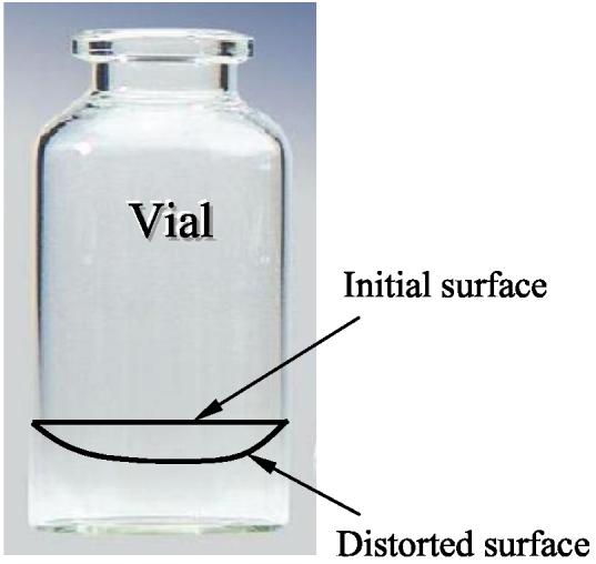
Schematic illustration of initial and distorted surfaces of cryoprotectant due to different thermal contractions of vial and cryoprotectant, which still must adhere to one another (distortion exaggerated).
The confining effect of the vial wall changes the stress distribution; this was investigated with finite element calculations. While we find the stresses near the center to be well calculated by integrating Eq. (3), the stresses are elevated above this value nearer to the edge. Contour plots depicting the distribution of the circumferential stress is shown in Fig. 10. The distribution of both the radial and circumferential stresses as a function of the radius, and at the mid height of the cryoprotectant (the dotted-dashed line in Fig. 10), are shown in Fig. 11. From the modestly elevated stresses, one would predict that cracking is more likely to occur near the wall. Further, the cracks have a slightly greater tendency to be in the radial direction, because the circumferential stress is predicted to be slightly larger than the radial stress. (The circumferential stress tends to open up cracks oriented in the radial direction.) These results are consistent with the experimental observation shown in Figs. 1-3.
Figure 10.

A contour plot showing spatial distribution of circumferential stress. The continuum mechanics problem is assumed axi-symmetric, subject to a uniform cooling rate of 5°C/min below −100°C, where the material develops characteristics of a solid. The stress distribution is representative of −120°C.
Figure 11.

Radial and circumferential stress distributions along the radius, at the mid height of the cryoprotectant (along the dotted-dashed line in Fig. 10).
Note that at this point only the directions of the stresses, not on their precise magnitudes, are of interest. Based on the fracture of ice, one expects fracture to occur at stresses on the order of one to several MPa. However, until we have data on the viscosity of cryoprotectant at low temperatures, its elastic modulus, and its fracture stress (which are currently under study in our laboratory), quantitative comparisons with observations of fracture are premature. Still, the stresses are of the right general magnitude.
All stress calculations discussed thus far were based on the assumption of a uniform temperature distribution. As shown in Fig. 5, this is clearly not realistic in typical cryopreservation conditions, although it could be achieved in thin samples and in special cases. Particularly for high cooling rates, the temperatures are quite non-uniform. Efforts are underway to develop the capability of predicting stresses when the temperatures are non-uniform (there are challenges in doing this when the viscosity changes by fourteen orders of magnitude during cooling). However, the dominant effect can be surmised with the following argument. As seen from the heat transfer simulations reported above, rapid cooling results in much colder temperatures in the cryoprotectant near the vial walls, and warmer temperatures near the center. As this liquid is cooled down, the outer portion will develop stress earlier, since its viscosity will be higher while the center portion is still comparatively low. Thus, under conditions of rapid cooling, one expects stresses to be significant in the outer portions and thus to cause cracking there first.
Summary
The cryomacroscope, presented first in Part I of this report, was used in this second part to investigate macrofractures in cryoprotectant samples contained in glass vials that are brought down to cryogenic temperatures. Observations of macrofractures at different cooling rates are contrasted, as are observations for different cryoprotectants. With rapid cooling, cracks appear in the outer regions of the cryoprotectant and move progressively inward with decreasing temperature. By contrast, at slow cooling rates, cracks appear nearly uniformly in the cryoprotectant. The appearance of cracks in cryoprotectant cocktail DP6 was far more common than in VS55. Either way, a distinct radial orientation is observed for fractures in the great majority of studied cases.
It is demonstrated in this study that fracture formation during cooling promotes crystallization during rewarming. Even in cases where fractures appear to heal during rewarming, crystals formed along prior fracture sites, at an advanced stage of rewarming. Although only a few images from three experiments are presented in this report, this study included 17 experiments which exhibited fractures, most of which are displayed in an accompanying web site [21]. In a few cases, crystals formed only along prior fracture sites.
Heat transfer analyses were used to estimate temperature distributions within the cryoprotectant. For the case of rapid cooling, the temperature is extremely nonuniform. Analyses of successive complexity were undertaken to explain various factors that affect cracking. The critical role of the vial in constraining the thermal contraction of cryoprotectant, and thereby creating tensile stress, was highlighted with a simple model of an elastic disk on a substrate. Next, the role of viscous deformation, or stress relaxation, was addressed; it was shown that negligible stresses arise even down to −100 °C, although this is dependent on the precise variation of viscosity with temperature. Finally, it is shown that the confining effect of the vial wall, and the non-uniformity in temperature, are both consistent with observations of cracking to be radial and to occur first in those portions of the cryoprotectant nearer to the vial wall. The concepts used in this paper to explain cracking are directly applicable to situations in which the cryoprotectant occupies a more substantial region. In addition, these concepts can be useful as one contemplates improved designs for cryopreservation protocols; for example, specimens may be vitrified in confining materials that more closely match the thermal expansion of cryoprotectant.
Acknowledgment
This study has been supported in part by NHLBI, grant number R01 HL069944. We would like to thank Dr. John R. Walsh and Mr. Shailendra Jain, Organ Recovery Systems, Inc., for obtaining some of the experimental data reported in this paper.
References
- 1.Brower WE, Freund MJ, Baudino MD, Ringwald C. An hypothesis for survival of spermatozoa via encapsulation during plane front freezing. Cryobiology. 1981;18:277–291. doi: 10.1016/0011-2240(81)90099-7. [DOI] [PubMed] [Google Scholar]
- 2.Diller KR, Cravalho EG. A microscope for the study of freezing and thawing processes in biological cells. Cryobiology. 1971;7:191–199. doi: 10.1016/0011-2240(70)90021-0. [DOI] [PubMed] [Google Scholar]
- 3.Fahy GM, Saur J, Williams RJ. Physical problems with the vitrification of large biological systems. Cryobiology. 1990;27:492–510. doi: 10.1016/0011-2240(90)90038-6. [DOI] [PubMed] [Google Scholar]
- 4.Ferry JD. Viscoelastic Properties of Polymers. 3rd ed. Wiley; New York: 1980. [Google Scholar]
- 5.Ishiguro H, Rubinsky B. Mechanical interaction between ice crystals and red blood cells during directional solidification. Cryobiology. 1994;31:483–500. doi: 10.1006/cryo.1994.1059. [DOI] [PubMed] [Google Scholar]
- 6.Korber CH, Scheiwe MW, Wollhover K. Solute polarization during planar freezing of aqueous solutions. J. Heat and Mass Trans. 1983;26:1241–1253. [Google Scholar]
- 7.Kroener C, Luyet BJ. Formation of cracks during the vitrification of glycerol solutions and disappearance of the cracks during rewarming. Biodynamica. 1966;10(201):47–52. [PubMed] [Google Scholar]
- 8.Luyet BJ, Rapatz G. An automatically regulated refrigeration system for small laboratory equipment and a microscope cooling stage. Biodynamica. 1957;7(154):337–345. [PubMed] [Google Scholar]
- 9.Mazur P, Leibo SP, Chu EHY. A two-factor hypothesis of freezing injury. Exp. Cell Res. 1972;71:345–355. doi: 10.1016/0014-4827(72)90303-5. [DOI] [PubMed] [Google Scholar]
- 10.Mehl P. Nucleation and crystal growth in a vitrification solution tested for organ cryopreservation by vitrification. Cryobiology. 1993;30:509–518. doi: 10.1006/cryo.1993.1051. [DOI] [PubMed] [Google Scholar]
- 11.Menz JL, Luyet BJ. A study of the lines of fracture observed in the freeze-drying of aqueous solutions crystallized into spherulites. Biodynamica. 1965;191:265–275. [PubMed] [Google Scholar]
- 12.Pegg DE, Wusteman MC, Boylan S. Fractures in cryopreserved elastic arteries. Cryobiology. 1997;34(2):183–192. doi: 10.1006/cryo.1996.1997. [DOI] [PubMed] [Google Scholar]
- 13.Pegg DE. Ice crystals in tissues and organs. In: Pegg DE, Karow AM, editors. The Biophysics of Organ Cryopreservation. Plenum Press; 1987. pp. 117–140. [Google Scholar]
- 14.Plitz J, Rabin Y, Walsh Y,JR. The effect of thermal expansion of ingredients on the cocktails VS55 and DP6. Cell Pres. Tech. 2004;2(3):215–226. [Google Scholar]
- 15.Rabin Y, Olson P, Taylor MJ, Steif PS, Julian TB, Wolmark N. Gross damage accumulation in frozen rabbit liver due to mechanical stress at cryogenic temperatures. Cryobiology. 1997;34:394–405. doi: 10.1006/cryo.1997.2010. [DOI] [PubMed] [Google Scholar]
- 16.Rabin Y, Shitzer A. Numerical solution of the multidimensional freezing problem during cryosurgery. ASME J. of Biomech. Eng. 1998;120(1):32–37. doi: 10.1115/1.2834304. [DOI] [PubMed] [Google Scholar]
- 17.Rabin Y, Taylor MJ, Wolmark N. Thermal expansion measurements of frozen biological tissues at cryogenic temperatures. ASME J. Biomech. Eng. 1998;120(2):259–266. doi: 10.1115/1.2798310. [DOI] [PubMed] [Google Scholar]
- 18.Rabin Y, Steif PS. Thermal stress modeling in cryosurgery. Int. J. Solids and Struc. 2000;37:2363–2375. [Google Scholar]
- 19.Rabin Y, Plitz J. Thermal expansion of blood vessels and muscle specimens permeated with DMSO, DP6, and VS55 in cryogenic temperatures. Annals of Biomedical Engineering. 2004 doi: 10.1007/s10439-005-5364-0. submitted. [DOI] [PubMed] [Google Scholar]
- 20.Rabin Y, Taylor MJ, Walsh JR, Baicu S, Steif PS. Cryomacroscopy of vitrification, Part I: A prototype and experimental observations on the cocktails VS55 and DP6. Cryobiology. 2005 doi: 10.1089/cpt.2005.3.169. submitted. [DOI] [PMC free article] [PubMed] [Google Scholar]
- 21.Cryomacroscopy of vitrification: selected experiments on DP6 and VS55. http://www.me.cmu.edu/faculty1/rabin/CryomacroscopyImages01.htm 2005
- 22.Rall WF. Factors affecting the survival of mouse embryos cryopreserved by vitrification. Cryobiology. 1987;24:387–402. doi: 10.1016/0011-2240(87)90042-3. [DOI] [PubMed] [Google Scholar]
- 23.Rubinsky B, Ikeda M. A microscope using directional solidification for the controlled freezing of biological material. Cryobiology. 1985;22:55–68. [Google Scholar]
- 24.Schichman SA, Amey RL. Viscosity and local liquid structure in dimethyl sulfoxide - water mixtures. J. of Phys. Chem. 1971;75(1):98–102. [Google Scholar]
- 25.Song YC, Khirabadi BS, Lightfoot FG, Brockbank KGM, Taylor MJ. Vitreous cryopreservation maintains the function of vascular grafts. Nature Biotech. 2000;18:296–299. doi: 10.1038/73737. [DOI] [PubMed] [Google Scholar]
- 26.Taylor MJ, Song YC, Brockbank KGM. In: Vitrification in tissue preservation: New developments, in: Life in the Frozen State. Fuller BJ, Lane N, Benson EE, editors. CRC Press; New York: 2004. [Google Scholar]
- 27.Thom F, Matthes G. Deformation of the cell membrane at low temperatures. I: A cryomicroscopical technique. Cryo-Letters. 1988;9:300–307. [Google Scholar]
- 28.Thom F. Deformation of the cell membrane at low temperatures. II: Elastical deformability of the erythrocyte membrane. Cryo-Letters. 1988;9:308–315. [Google Scholar]
- 29.Williams RJ, Carnahan DL. Four modes of nucleation in viscous solutions. Cryobiology. 1989;26(6):568. [Google Scholar]
- 30.Williams RJ, Carnahan DL. Fracture faces and other interfaces as ice nucleation sites. Cryobiology. 1990;27(5):479–482. doi: 10.1016/0011-2240(90)90036-4. [DOI] [PubMed] [Google Scholar]
- 31.Boley BA, Weiner JH. Theory of Thermal Stresses. Wiley; New York: 1960. [Google Scholar]
- 32.Linfor JJ, Meyers SA. Detection of DNA damage in response to cooling injury in equine spermatozoa using single-cell gel electrophoresis. Journal of Andrology. 2002;23(1):107–113. doi: 10.1002/j.1939-4640.2002.tb02603.x. [DOI] [PubMed] [Google Scholar]
- 33.Fahy GM, Wowk B, Wu J, Paynter S. Improved vitrification solutions based on the predictability of vitrification solution toxicity. Cryobiology. 2004;48:22–35. doi: 10.1016/j.cryobiol.2003.11.004. [DOI] [PubMed] [Google Scholar]
- 34.de Freitas RC, Diller KR, Lakey JRT, Rajotte RV. Osmotic behavior and transport properties of human islets in a dimethyl sulfoxide solution. Cryobiology. 1997;35:230–239. doi: 10.1006/cryo.1997.2045. [DOI] [PubMed] [Google Scholar]