Abstract
This paper presents the methods used for three-dimensional (3D) reasoning about anatomic structures affected by penetrating trauma in TraumaSCAN-Web, a platform-independent decision support system for evaluating the effects of penetrating trauma to the chest and abdomen. In assessing outcomes for an injured patient, TraumaSCAN-Web utilizes 3D models of anatomic structures and 3D models of the regions of damage associated with stab and gunshot wounds to determine the probability of injury to anatomic structures. Probabilities estimated from 3D reasoning about affected anatomic structures serve as input to a Bayesian network which calculates posterior probabilities of injury based on these initial probabilities together with available information about patient signs, symptoms and test results. In addition to displaying textual descriptions of conditions arising from penetrating trauma to a patient, TraumaSCAN-Web allows users to visualize the anatomy suspected of being injured in 3D, in this way providing a guide to its reasoning process.
Keywords: Decision support, 3D modeling, Expert systems
1. Introduction
Penetrating trauma is a medical and social problem that affects most regions of the United States. United States penetrating trauma statistics from the Centers for Disease Control and Prevention (CDC) between 1999 and 2002 show a 10.35% crude death rate (number of deaths per 1000 people) from firearm injuries (a total of 117,352 deaths) and a 0.88% crude death rate from stab injuries (a total of 9951 deaths) [1]. An examination of the leading causes of death in the US between 1999 and 2002 shows that homicides and/or suicides feature among the top 10 leading causes of death in the US for people between the ages of 1 year and 64 years. Deaths from firearms make up a significant portion of these deaths, with more than 55% of deaths by homicide occurring from firearms in persons between the ages of 10 years and 44 years, and more than 35% of all deaths by suicide occurring from firearms in persons between the ages of 10 and 64 years of age [2].
To explore the ways in which computer-based decision support could be beneficial in managing penetrating trauma cases, TraumaSCAN was developed [3]. TraumaSCAN is a computer system for assessing chest and abdominal penetrating trauma. It computes the probability of injury to anatomic structures and the probability of consequent conditions, such as pneumothoraces and hemothoraces, using geometric reasoning about anatomic structure involvement and probabilistic reasoning with Bayesian networks. In a retrospective assessment of 26 gunshot wound cases utilizing external wound location, bullet location, and other patient findings as input, TraumaSCAN was shown to have good sensitivity and specificity, with areas under the ROC curve ranging from 0.835 (in the worst case) to 0.992 (in the best case) for 11 conditions present in the cases assessed [4]. While the Bayesian network and approach used for probabilistic reasoning in Trauma-SCAN have been described in detail elsewhere [4], the anatomic reasoning approach has not.
TraumaSCAN was developed in C and C++ and ran only on Silicon Graphics machines (to take advantage of that platform’s dedicated graphics hardware). Advances in graphics hardware now make it feasible to perform 3D graphics computations in real-time on a desktop PC or lap-top, though many graphically intensive programs run slower on these computers. Since these advances present an opportunity for increased dissemination and deployment, a platform-independent version of TraumaSCAN called TraumaSCAN-Web [5] has recently been developed at the Decision Systems Group to replace the original. TraumaSCAN-Web utilizes Java, Java3D (an application programmer interface created by Sun for programming complex 3D graphics scenes in Java) and Open-GL (an open-source graphics library that is a standard for developing portable 3D graphics applications). It utilizes a Bayesian network model that updates the number of penetrating trauma related conditions that can be assessed and corrects an error discovered in the previous model and described in an earlier paper [4]. TraumaSCAN-Web also incorporates new methods for geometric reasoning about injuries to anatomic structures from gunshot and stab wounds. A recent analysis of TraumaSCAN-Web’s performance on retrospective multi-center data was performed. Of the 23 conditions modeled in TraumaSCAN-Web, the patient data contained 19. The 23 conditions modeled in Trauma-SCAN-Web cover damage to chest and abdominal soft organs (e.g., the lungs, heart, diaphragm, liver, stomach, kidneys, and intestine), some major blood vessels, and common conditions arising from these injuries such as pneumothoraces, hemothoraces and cardiac tamponade. Injuries to skeletal structures and minor blood vessels are not explicitly assessed. Areas under the ROC curve (AUCs) for this data ranged from 0.519 to 0.975 for gunshot injuries and from 0.701 to 1.0 for stab injuries [6]. This paper examines in detail the methods used in TraumaSCAN-Web for anatomic reasoning about ballistic and stab injury to chest and abdominal structures.
2. Related work
Related work on computer based systems for assessing penetrating trauma includes TraumAID [7,8], an expert system for assisting physicians with the diagnosis and treatment of conditions arising from penetrating trauma to the chest and abdomen. TraumAID uses a rule-based reasoner to identify diagnostic and therapeutic goals that are appropriate for a particular patient’s state and provides textual feedback to the user. It does not explicitly model anatomy and anatomic relationships, and so cannot provide the deeper reasoning about anatomic involvement in injury that TraumaSCAN-Web does.
Work on probabilistic modeling of the consequences of penetrating trauma includes Hirshberg et al. ’s [9] study of neural networks as a means of predicting the need for damage control in abdominal gunshot injuries. Their study shows that bullet trajectory information and blood pressure findings are important predictors of outcomes for patients with abdominal gunshot wounds. It complements results observed for TraumaSCAN-Web, which incorporates mechanism of injury information via geometric models of damage to anatomic structures. TraumaSCAN-Web also utilizes patient findings related to blood pressure values, such as hemodynamic shock, in its Bayesian network model, which is used to produce a more diagnostically refined assessment of the effects of thoracoabdominal penetrating trauma.
Related research on understanding the effects of gunshot injuries on humans includes: utilizing 3D graphics methods for determining the paths taken by projectiles [10]; estimating the incapacitation to humans caused by different types of projectiles [11]; examining approaches for reducing ballistic casualties [12]; modeling and simulating penetrating injury to the extremities [13]; examining how missiles interact with tissue [14]; and, using high-speed video photography to analyze the wounding mechanics of a variety of low-velocity projectiles [15]. These studies examine the effects of projectiles on tissue through simulation and other means to assess the magnitude of resulting injuries. These approaches provide a wealth of information on ballisticpenetration paths, utilizing explicit knowledge of the types of projectiles used, projectile velocities and directions of entry into tissue. TraumaSCAN-Web, on the other hand, is designed to approach the assessment of penetrating trauma using only those details that would ordinarily be available to health care providers presented with a trauma patient. Thus, the process of assessing injury effects in Trauma-SCAN-Web is implemented in such a way that the system proceeds in the absence of detailed information on projectiles and their characteristics, as this information is rarely available to providers prior to treating a trauma patient.
3. Methods: geometric reasoning in traumaSCAN-Web
Reasoning about the consequences of penetrating injury should take into account the mechanism of injury and the structures of the body to which injury occur. As described above, TraumaSCAN-Web’s reasoning about injury consequences has to proceed in the absence of information about bullet type, bullet velocity, or direction of entry. The fact that there may be limited information available about the mechanism of injury is one of the uncertainties associated with assessing the effects of penetrating trauma.
In the case of stab wounds, reasoning about injury consequences is complicated by the fact that the direction and penetration depth of a weapon may be unknown. For multiple gunshot wounds, there are different complications. One is that it is not always possible to tell whether a wound is an entry or an exit wound. This implies that two external wounds that are in reality both entry wounds (or both exit wounds) might be hypothesized as being an entry-exit pair, and incorrect inferences about affected structures may result. Another complication is that many different pairings are possible among entry and exit wounds or entry wounds and bullets lodged in the body. Different pairings may correspond to different hypotheses about internal injuries for the same set of external wounds and bullets.
TraumaSCAN-Web is meant to use information about the mechanisms of injury, anatomical structures affected by injury, and patient findings to determine a patient’s diagnoses. To assess anatomic injuries for a given patient, several issues must be addressed, including:
modeling the regions of damage associated with a particular mechanism of injury,
devising strategies for identifying injured structures and for calculating the probability of injury to these structures.
The approaches used for tackling these issues will be discussed in detail in the sections that follow.
TraumaSCAN-Web utilizes a three-dimensional model of a torso that includes 3D models of internal soft and skeletal structures to assess the effects of thoracoabdominal penetrating trauma. The outer boundary of a three dimensional object can be represented by a closed 3D mesh of polygons (a polygon is a planar region that is fully enclosed by three or more lines). Polygon meshes are often used for modeling 3D objects because they are easy to specify and manipulate. Although objects that are not smoothly curved (such as pyramids, cubes, and some chairs and tables) can be represented exactly using polygon meshes, 3D objects that are smoothly curved (such as internal organs) can only be approximated. In many cases, by increasing the number of polygons used, it is possible to obtain a more accurate polygon mesh model of a 3D object. TraumaSCAN-Web uses polygon meshes referred to as polygonal surface models for representing 3D objects. However, increasing the number of polygons in a model may also increase the time required to display the model and perform computations with it. Since some computations involving a 3D object’s polygonal surface model require examination of each individual polygon, there is a necessary trade-off between the level of detail required to satisfactorily represent an object and the computational expense that results from having a large number of polygons. Fig. 1 shows coarse and fine wireframe polygonal surface representations of the same sphere.
Fig. 1.
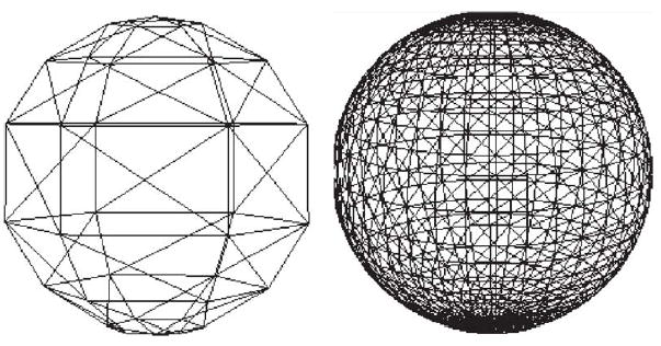
Low resolution (left) and high-resolution (right) polygonal surface models of a sphere.
The organs, skeleton, and skin for the three-dimensional torso model used by TraumaSCAN-Web are polygonal surface models developed at Viewpoint DataLabs (New York, NY) and converted to VTK [16] format for use in TraumaSCAN-Web. Polygonal surface models of some major blood vessels (descending aorta, carotid and subclavian arteries, etc.) were developed based on reconstructions from CT-scan data using SPAMMVU [17] and descriptions from anatomy texts [18–20]. All 3D models were triangulated (each polygon broken down into triangles so that the surface is approximated by these triangles) to ensure that each polygon’s vertices lie in the same plane, to facilitate intersection computations, and because graphics rendering hardware is often optimized for triangle primitives. Polygon counts for some of the anatomic structures utilized by TraumaSCAN-Web are given in Table 1 below.
Table 1.
Some structures and their polygon counts in TraumaSCAN-Web
| Anatomic structure | Polygon count |
|---|---|
| Heart | 1116 |
| Left lung | 288 |
| Right lung | 288 |
| Liver | 274 |
| Diaphragm | 412 |
| Stomach | 534 |
| Pancreas | 358 |
| Trachea | 1768 |
| Gallbladder | 412 |
3.1. Modeling regions of damage for an injury mechanism
In assessing the effect of a projectile, TraumaSCAN-Web takes into account the possible paths traced by the projectile and the fact that injury results not only from the direct path made by a projectile, but also from cavitation effects. The model for approximating the region of damage associated with a projectile reflects these observations. Based on studies of cavitation associated with ballistic injury, a conjoined cone model is used for these injuries (see illustration in Fig. 2). For injury assessment, the damage model is oriented in such a way that one apex corresponds to an entry wound location and the other to an exit wound or bullet location. The ratio of each damage model’s length to its maximum diameter is fixed at 100:18, based on values obtained from [21,22] of the dimensions of length to maximum diameter for permanent and temporary wound cavities produced in injuries involving high velocity projectiles. Projectile ricochet is not directly modeled by the system.
Fig. 2.
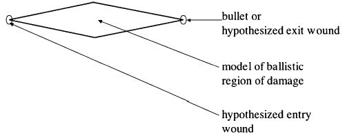
Model of ballistic region of damage.
For stab assessments, there is often no information about the direction in which a blade used penetrates the body, or the depth of entry of the blade. A truncated ellipsoidal model that captures uncertainty about the direction of entry of a blade is used for these injuries (see Fig. 3). Also, a default penetration depth that covers 80% of the length from the chest to the back of TraumaSCAN-Web’s torso model is used. This means that for superficial stab injury cases, the geometric reasoning model will likely overestimate injury to structures. TraumaSCAN-Web’s design: coupling geometric reasoning with diagnostic reasoning based on Bayesian networks, ensures that initial injury probability estimates derived from the geometric reasoning step are refined based on information about the presence or absence of patient signs and symptoms. This coupled design moderates the over- or under-estimation of injury to structures. For superficial stab injury cases, the absence of patient findings that would be expected in cases involving injury to internal structures would cause probabilities of injury to be revised downward.
Fig. 3.
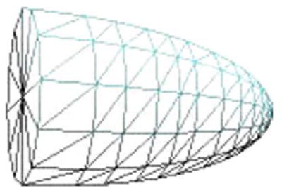
Model of stab region of damage.
3.2. Injury assessment methods
This section describes the methods used for identifying possibly injured anatomic structures and for determining a structure’s probability of injury. To aid the reader in understanding the rationale behind the assessment approach employed for ballistic injuries, some of the factors that complicate the assessment of ballistic injuries are described next.
For a patient with multiple external wounds and possibly bullets lodged in the body, there may be different plausible hypotheses for the paths taken by projectiles. Each hypothesis involves specifying connections between entry wounds and exit wounds or bullets. To illustrate this, I use the following example: A patient presents with four external wounds to the chest: two anterior (left and right) and two posterior (left and right). It is not known which of the wounds are entry or exit wounds and the assumption is that the patient was shot twice and each bullet entered and exited the body, producing two through-and-through wounds. In this case, there are three1 possible hypotheses (Fig. 4):
Fig. 4.

Three different wound track hypotheses corresponding to a set of external gunshot wounds.
The left anterior wound and the left posterior wound are part of the same wound track, similarly for the right side (i.e., the wound tracks are parallel from anterior to posterior—see Fig. 4A).
The left anterior wound and the right posterior wound are part of the same wound track, and the right anterior and left posterior wounds belong to the same wound track (i.e., the wound tracks cross—see Fig. 4B).
The left anterior wound and the right anterior wound belong to the same wound track, similarly for the left and right posterior wounds (i.e., the wound tracks are parallel from right to left—see Fig. 4C).
These three hypotheses could produce markedly different consequences for a patient. The hypothesis associated with Fig. 4C might result in mainly superficial injuries, whereas that for Fig. 4A might involve injury to the lungs and abdomen. In the case corresponding to Fig. 4B, there could be injury to the lungs, heart, abdomen, and major blood vessels.
Given a gunshot case involving a single entry wound and no exit wound, only one possibility exists: there must be a bullet lodged somewhere in the body. In this case, a single path can be postulated from the entry wound to the bullet and there is just one wound track hypothesis. With two external gunshot wounds, one of the wounds might be an entry wound and the other an exit wound (resulting in a through-and-through wound track), or the wounds could be two separate entry wounds linked to two bullets retained in the body. Generalizing this, if there are i external gunshot wounds and j through-and-through wound tracks involving 2j of the i wounds, then the number of hypotheses produced is
| (1) |
For a few values of i, Table 2 gives the number of hypotheses possible for i external wounds, j through-and-through wound tracks (j may be 0), and b bullets found internally (where b = i − 2j), based on Eq. (1). Blank values in the table represent combinations the TraumaSCAN-Web system would reject as inconsistent, for example, having the total number of external wounds and bullets sum to an odd number. As can be seen from Table 2, the number of possible ballistic injury hypotheses increases exponentially as the number of external wounds and bullets increases.
Table 2.
Hypotheses given i external wounds, b bullets, and j through-and-through wound tracks (where b = i − 2j)
| b = 0 | b = 1 | b = 2 | b = 3 | b = 4 | b = 5 | b = 6 | |
|---|---|---|---|---|---|---|---|
| i = 1 | 1 | ||||||
| i = 2 | 1 | 2 | |||||
| i = 3 | 3 | 6 | |||||
| i = 4 | 3 | 12 | 24 | ||||
| i = 5 | 15 | 60 | 120 | ||||
| i = 6 | 15 | 90 | 360 | 720 | |||
| i = 7 | 105 | 630 | 2520 | ||||
| i = 8 | 105 | 840 | 5040 | 20,160 | |||
| i = 9 | 945 | 7560 | 45,360 | ||||
| i = 10 | 945 | 9450 | 75,600 | 456,300 | |||
| i = 11 | 10,395 | 103,950 | 831,600 | ||||
| i = 12 | 10,395 | 124,740 | 1,247,400 | 9,979,200 |
Although an exploration of all possible hypotheses would be desirable in assessing multiple gunshot wound cases, this is clearly infeasible due to the amount of time that would be required and the desire to keep Trauma-SCAN-Web interactive. A two-pronged approach is used to handle gunshot injury assessment in TraumaSCAN-Web. For four or fewer external wounds, all hypotheses are explored fully (for a maximum of 24 hypotheses). This is based in part on evidence from penetrating trauma data collected at Brigham and Women’s Hospital and MCP-Hahnemann University that the majority of gunshot cases that make it to the hospital involve four or fewer wounds. For five or more wounds, a hypothesis is chosen at random from the space of possible hypotheses and fully explored. This approach exploits the fact that as the number of external wounds increase, there are common external wound pairings that occur across different hypotheses to be explored, and thus similar structures injured for these different hypotheses. In other words, as the number of external wounds for a patient exceeds four, we begin to see that different hypotheses for the same set of external wounds include many of the same wound tracks and consequently, many of the same injuries, so it may not be necessary to explore each hypothesis in turn.
To generate the set of possible hypotheses for four or fewer wounds, we make use of the knowledge that solving the problem for i wounds and b bullets involves solving sub-problems for i − 1 wounds and b − 1 (i ≥ 2, b ≥ 2) bullets. Using dynamic programming, we create a table of the possible wound pairings for each hypothesis. The pairings represented in the table are utilized in the assessment of different ballistic injury cases.
3.2.1. Identifying injured anatomic structures and calculating injury probabilities
In TraumaSCAN-Web, to determine which anatomic structures may have been injured for a given patient, once external wound (and where appropriate, bullet) locations are identified, all intersections between the 3D region of damage models corresponding to a mechanism of injury and the 3D models of anatomic structures are computed. The polygonal surface models of anatomic structures and regions of damage used by TraumaSCAN-Web may contain hundreds or thousands of polygons (the polygon count varies from one 3D model to another and depends on the model’s resolution). To reduce computational overhead, intersection computations take place in two steps, with the first step being a quick way of reducing the set of anatomic structures that need to be considered for the second, more computationally intensive step.
First, the smallest axis-aligned bounding boxes that enclose each anatomic structure and each region of damage model are computed. (Fig. 5 shows the bounding box for the polygonal surface representation of a diaphragm.) If a vertex of the bounding box for an anatomic structure lies within the bounding box for a damage model or vice-versa, the structures enclosed by these boxes are noted as candidates for intersection. All anatomic structures that are determined to intersect a region of damage model in this step are stored for the second step. The use of bounding boxes in the first step ensures that at most eight vertex comparisons occur for a given anatomic structure (as opposed to hundreds or thousands of comparisons in the worst case). Since bounding boxes give at best a rough estimate of the shape and size of a figure, the first step may yield false positives, detecting bounding box intersections in cases where the actual structures enclosed by these boxes are not intersecting. For example, the bounding box for the diaphragm is much larger than the actual figure due to the concavity of the diaphragm, and as a result, bounding box intersection computations involving the diaphragm may yield false positives. The first step does not yield false negatives: it will not omit from further consideration any organs that could intersect with a given region of damage model.
Fig. 5.
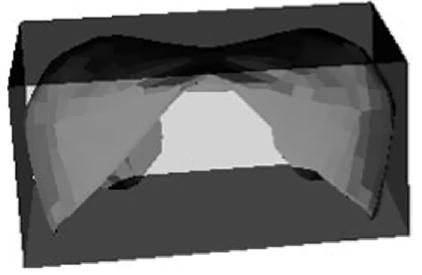
Bounding box for the polygonal surface representation of a diaphragm.
The second step involves more detailed intersection checks for the anatomic structures identified as possibly intersecting a damage model by the previous step. The polygon vertices and edges that make up each 3D damage model are checked for intersection with the polygon vertices and edges that comprise the identified anatomic structures. Computational geometry algorithms for fast intersection computations [23,24] are used in this step to identify those anatomic structures that intersect the region of damage models. To check intersection of two triangles t1 and t2 belonging to two different anatomic structure models, the fast intersection methods involve computing the plane equation for each triangle and calculating the signed distance from each vertex of triangle t1 to the plane in which triangle t2 lies. If all distances are nonzero and have the same sign, triangle t1 does not intersect t2. This process is repeated for triangle t2’s vertices and the plane in which triangle t1 lies. If triangles t1 and t2 are not rejected for non-intersection after calculating their vertices’ signed distances, we determine the line L representing the intersection of the planes in which the two triangle lie. We then check each triangle edge’s intersection with L. Each edge intersection for triangles t1 and t2 forms an interval on L. If the intervals from the different triangles overlap, t1 and t2 intersect. When the triangles are coplanar (the signed distances measured in the first step are zero), we project both triangles onto the same plane and perform a 2D triangle–triangle overlap test to determine whether they intersect.
Once each anatomic structure suspected of being injured has been identified in the second step, the probability that the structure is injured can be computed. For both gunshot and stab wounds, we can relate the probability of an anatomic structure being injured to the proportion of the structure’s cross-sectional area that intersects the cross-sectional area of the associated region of damage model. The cross-sectional slices of a ballistic or stab region of damage models (for example, as seen when looking from one apex of the conjoined cone model to the other apex) would be a series of concentric circles (see Fig. 6A). For each anatomical structure determined to intersect a region of damage, one could project the cross-sectional slices of the structure and damage model onto a 2D plane (e.g., see Fig. 6B). For different cross-sectional slices of a region of damage model, the ratio of the proportion of an anatomic structure’s cross-sectional area that intersects the region of damage cross-section can be calculated. The injury probability for the anatomical structure would then be the maximal ratio calculated since that would correspond to the greatest amount of injury. A 3D approach that is equivalent to the steps outlined above is what we actually use for injury probability calculations and is described below.
Fig. 6.
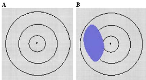
Region of damage model cross-sections projected onto a 2D plane.
The injury probability, or hit probability, for a given anatomic structure is calculated by casting a number of rays randomly from one end of the region of damage that intersects the structure to another and checking how many of the rays generated intersect the structure in question (see Fig. 7). Each ray generated either intersects a structure (a hit) or does not (a miss). The total number of rays that intersect an anatomic structure is represented by the binomial random variable X with parameters n and p, where n is the total number of rays generated and p the probability of a hit. The sample hit probability for the anatomical structure, , is defined as the mean number of hits for the particular number of rays generated, and is the maximum likelihood estimator for p (the true hit probability). Confidence bounds for a given hit probability are determined using a normal approximation to the binomial distribution [25,26].
Fig. 7.
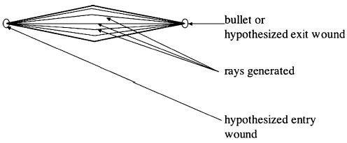
Ballistic region of damage model featuring generated rays.
The amount of computation time required to calculate the sample hit probability of an anatomic structure increases linearly with the number of rays generated. A goal is to increase precision in estimating p while minimizing computation time. This goal can be achieved by estimating the smallest number of random rays generated that ensure a 95% confidence interval for , which implies that
Since the denominator is fixed, the largest possible value for the numerator is used. Table 3 shows that p(1 − p) is maximal when p = 0.5.
Table 3.
Number of rays to be generated for hit probability estimation
| p | ">p(1 − p) | Number_of_rays |
|---|---|---|
| 0.0 | 0.00 | 0 |
| 0.1 | 0.09 | 139 |
| 0.2 | 0.16 | 246 |
| 0.3 | 0.21 | 323 |
| 0.4 | 0.24 | 369 |
| 0.5 | 0.25 | 385 |
| 0.6 | 0.24 | 369 |
| 0.7 | 0.21 | 323 |
| 0.8 | 0.16 | 246 |
| 0.9 | 0.09 | 139 |
| 1.0 | 0.00 | 0 |
The number of rays generated to estimate an anatomic structure’s probability of injury is thus 385. Note that a larger number of rays can still be generated to enhance the precision of estimated probabilities (at the expense of an increase in computation time).
For gunshot cases, each ray generated extends from one apex of the region of damage to the other and is generated based on two randomly produced angles, θ and φ. The angle θ determines a ray’s deviation from a straight line path (Fig. 8) and the angle φ specifies the amount of rotation about a damage model’s apex (see Fig. 9).
Fig. 8.

Angle theta (θ).
Fig. 9.
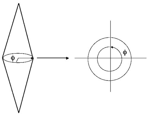
Angle phi (φ).
Both θ and φ are produced using pseudo-random number generators. For gunshot cases, the probability that a structure is hit increases based on its proximity to the center of the region of damage model. This is incorporated into the geometric reasoning methods by generating rays that are more likely to occur close to the center of the model than close to its boundaries (i.e., rays are more likely to follow a straight line path than deviate). To test the impact of this hypothesis on trauma assessment, θ was generated according to a normal, triangular, and uniform distributions for assessing a set of 26 patient cases. (With the normal and triangular distributions, rays generated are more likely to follow a straight line path than deviate.) The results of evaluating 26 trauma cases showed that assessments made using a θ generated according to the normal distribution produced the best diagnostic assessments relative to the gold standard (actual penetrating trauma diagnoses recorded in patient charts) [3].
The approach to assessing stab injury probabilities is very similar to that just outlined for gunshot wound cases (generating rays and determining the sample hit probabilities for each anatomic structure that intersects a stab region of damage model). For multiple stab and multiple gunshot injury cases, there is the added step of finding the overall hit probability for anatomic structures that may have been injured more than once. I will illustrate this process with a multiple stab wound example though the same methods would apply to finding the overall hit probability for a structure given one gunshot injury hypothesis.
When a patient case involves multiple stab injuries, TraumaSCAN-Web uses independent stab regions of damage models to represent each stabbing. Each independent intersection of a region of damage model with a structure contributes to the structure’s overall probability of being injured. If there are k region of damage models present, the overall hit probability for an anatomic structure is given by
where is the sample hit probability of the anatomic structure for the ith region of damage model, and is the probability that none of the region of damage models present affects the anatomical structure. In other words, determining the overall hit probability for a structure involves calculating the overall probability that it is not injured, and finding the complement of that value. To illustrate this with a concrete example, imagine an injury scenario in which a patient is stabbed four times. There are four stab region of damage models (S1, S2, S3, and S4) and three of the four have been determined to penetrate the heart. If the hit probability for the heart given S1 is 1.0 (that is, there is absolute certainty that the heart is hit in this case), for S2 is 0.75, for S3 is 0.35, and for S4 is 0.0, we would expect the overall hit probability for the heart to be 1.0, since we are absolutely certain that the heart was hit. Using the formula above, we get an overall probability of 1 − [(1 − 1) × (1 − 0.75) × (1 − 0. 35) × (1 − 0.0)] = 1, as expected.
3.3. System illustration
To assess outcomes for a patient, a user inputs external wounds from gunshots or stabbings onto a rotatable 3D model of a human torso by selecting the appropriate menu option and clicking over the desired location on the torso (a 3D marker of the wound location appears on the selected area of the torso). The user can then begin the reasoning process to determine possible injury to anatomical structures for the wounds entered by selecting appropriate menu options (see Figs. 10–14 below).
Fig. 10.
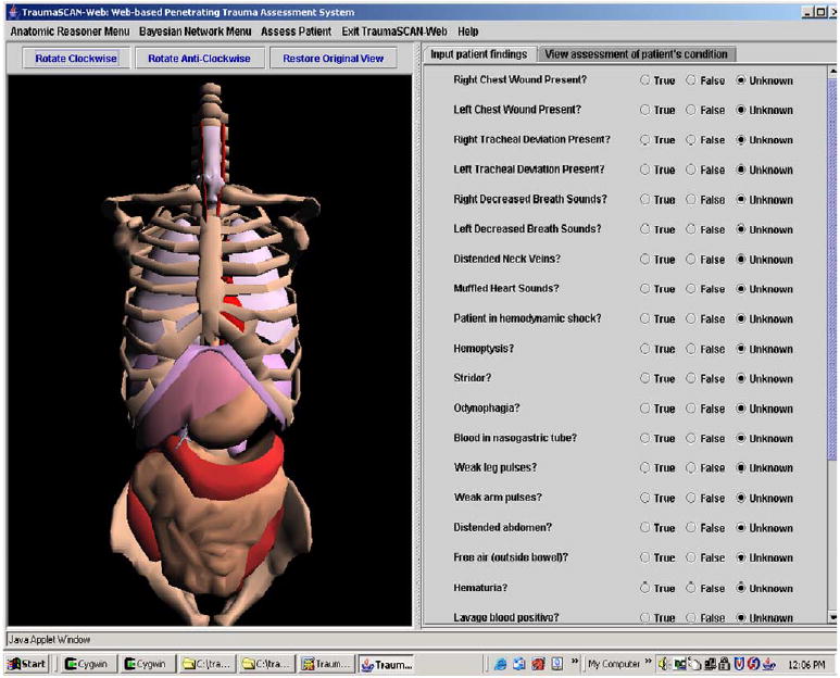
TraumaSCAN-Web user interface display. (For interpretation of the references to colors in this figure legend, the reader is referred to the web version of this paper.)
Fig 14.
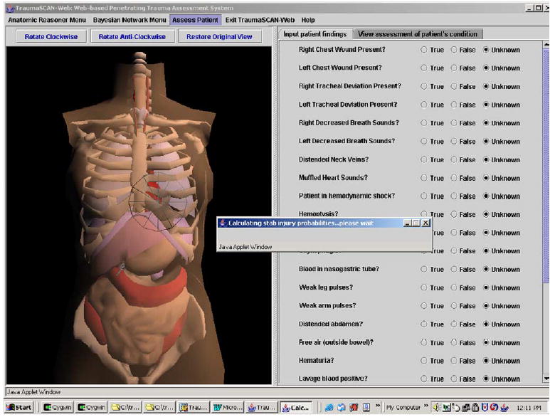
Assessing a stab injury.
The TraumaSCAN-Web display has the elements corresponding to the geometric reasoner on the left, and buttons indicating the presence or absence of different patient findings (utilized by the Bayesian network for probabilistic reasoning) on the right.
Fig. 11 shows the process of ballistic external wound placement on the torso’s skin (the red circle that appears on the left is the external wound). The user can specify that a wound is an entry wound, an exit wound, or that its role in injury is unknown.
Fig. 11.
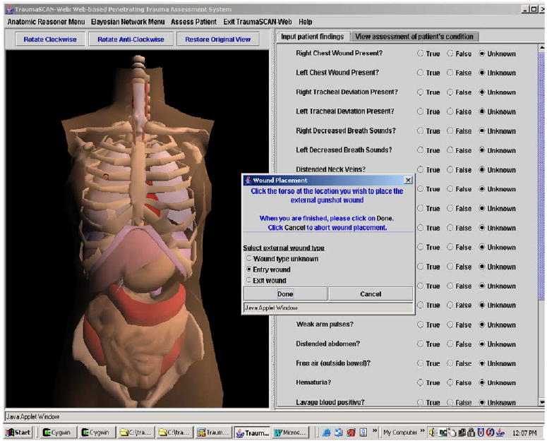
Marking external gunshot wounds on the torso. (For interpretation of the references to colors in this figure legend, the reader is referred to the web version of this paper.)
Fig. 12 illustrates three-dimensional bullet placement within the torso. The bullet is at the center of the red cross-hairs.
Fig. 12.
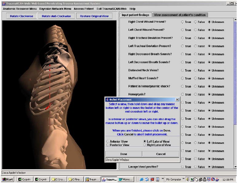
Placing a bullet within the torso. (For interpretation of the references to colors in this figure legend, the reader is referred to the web version of this paper.)
Fig. 13 shows the results of a ballistic injury assessment: posterior probabilities of injury and various conditions are displayed in the text area on the right, while the anatomic structures on the left are highlighted based on the posterior probabilities calculated by the diagnostic reasoner’s Bayesian network. Table 4 relates the color shading utilized to posterior probabilities of organ injury calculated by the Bayesian network. This provides the user with immediate visual cues about the degree of injury to different anatomic structures.
Fig. 13.
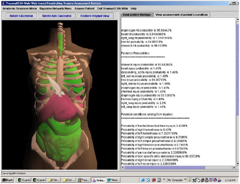
Ballistic trauma assessment results. (For interpretation of the references to colors in this figure legend, the reader is referred to the web version of this paper.)
Table 4.
Color shading based on posterior probabilities
| Posterior probability of injury (range) (%) | Color shading |
|---|---|
| [0, 24] | Green |
| [25, 49] | Yellow |
| [50, 74] | Orange |
| [75, 100] | Fuchsia |
4. Discussion
This paper has described the methods used for geometric reasoning in TraumaSCAN-Web, a Java based system that utilizes geometric reasoning about anatomic involvement in injury and probabilistic reasoning about injury consequences to assess thoraco-abdominal penetrating trauma from gunshot and stab wounds.
Potential limitations of TraumaSCAN-Web that arise as a result of uncertainty inherent in the problem to be solved are its treatment of projectile ricochet and variances in bodily proportions across individuals.
Ricochet occurs when a projectile is deflected from its original course through the body as a result of hitting a dense mass (such as bone). With ballistic injuries, projectiles may ricochet off bone, but it is not in general possible to predict when and how this will happen. It would thus be very difficult to try to assess the effects of ricochet for a primary projectile or for secondary projectiles such as bone fragments and fragments of primary projectiles. For this reason, ricochet is not treated directly within the framework of geometric modeling. Although ricochet may not occur frequently, the consequences are unusual enough that physicians who have had to deal with such cases tend to remember them more than other cases and as such, attach a lot of significance to them. The diagnostic reasoner may be able to assist with reasoning about cases involving projectile ricochet when patient signs and symptoms are present that help indicate effects of projectiles beyond the geometric reasoner’s projected ballistic paths.
Individuals vary with respect to their shapes and proportions and with respect to the sizes and placement of their internal organs. This means that there are potential differences in the scope of damage for people with similar external wounds. Modeling differences in individuals with respect to the body volume occupied by their chest or abdominal cavities could be done by scaling the geometric representation of the skin so that the space between the skin and internal structures approximates this. While it might be possible to create geometric models of humans that make use of anthropometric data, in general, it may not be possible to obtain information about an individual’s internal structure prior to system use, and so there is really no means of dynamically adapting our geometric models to fit an individual’s exact profile. However, this does not mean that the system’s output will be irrelevant: in the same way that standard anatomical models are of use in conveying information about anatomy (a case in point is the fact that medical students learn much about anatomy from standardized models and descriptions given in textbooks), It should be noted that two patients of markedly different sizes with the same external injury locations may have different signs, symptoms and test results, and these differences will influence the posterior probabilities of injury calculated byTraumaSCAN-Web. Thus, TraumaSCAN-Web may still be of use in presenting information about potential consequences of injury. The promising results obtained from evaluating TraumaSCAN-Web on multi-center patient data appear to bear out this view.
Currently in progress is a retrospective study of TraumaSCAN-Web’s effect on the penetrating trauma diagnoses of Brigham and Women’s Hospital emergency department residents. Future areas of interest include development and evaluation of PDA-based versions of the system that could be used by EMTs to relay detailed patient information prior to arriving at a hospital’s emergency department.
Acknowledgments
This work has been supported by Grant No. R01 LM07167-01 from the National Library of Medicine.
Footnotes
It is not necessary to account for the direction in which a projectile traveled.
References
- 1.Centers for Disease Control and Prevention. WISQARS Injury Mortality Reports, 1999–2002. <http://webappa.cdc.gov/sasweb/ncipc/mortrate10_sy.html>.
- 2.Centers for Disease Control and Prevention. WISQARS Leading Causes of Death Reports, 1999—2002. <http://webapp.cdc.gov/sasweb/ncipc/leadcaus10.html>.
- 3.Ogunyemi O. TraumaSCAN: Assessing Penetrating Trauma with Abductive and Geometric Reasoning [PhD Thesis]. Philadelphia: University of Pennsylvania; 1999.
- 4.Ogunyemi OI, Clarke JR, Ash N, Webber BL. Combining geometric and probabilistic reasoning for computer-based penetrating-trauma assessment. J Am Med Inform Assoc. 2002;9(3):273–82. doi: 10.1197/jamia.M0979. [DOI] [PMC free article] [PubMed] [Google Scholar]
- 5.http://dsg.harvard.edu~oogunyem/traumascan/ Accessed on March 21, 2005>.
- 6.Matheny ME, Ogunyemi OI, Rice PL, Clarke JR. Evaluating the Discriminatory Power of a Computer-based System for Assessing Penetrating Trauma on Retrospective Multi-Center Data. Proceedings of the American Medical Informatics Association Annual Fall Symposium 2005:500–4. [PMC free article] [PubMed]
- 7.Rymon R, Webber BL, Clarke JR. Progressive horizon planning—planning exploratory-corrective behavior. IEEE Trans Syst Man Cybernetics 1993;23(6).
- 8.Webber B, Rymon R, Clarke JR. Flexible support for trauma management through goal-directed reasoning and planning. Artif Intell Med. 1992;4(2):145–63. [Google Scholar]
- 9.Hirshberg A, Wall MJ, Mattox KL. Bullet trajectory predicts the need for damage control an artificial neural network model. J Trauma Inj Infect Crit Care. 2000;52:852–8. doi: 10.1097/00005373-200205000-00006. [DOI] [PubMed] [Google Scholar]
- 10.Wind G, Finley RW, Rich NM. Three-dimensional computer graphic modeling of ballistic injuries. J Trauma Inj Infect Crit Care. 1988;28(Suppl 1):S16–20. doi: 10.1097/00005373-198801001-00006. [DOI] [PubMed] [Google Scholar]
- 11.Eisler RD, Chatterjee AK, Burghart GH, O’Keefe JA. Casualty assessment of penetrating wounds from ballistic trauma. Technical Report MRC-COM-R-93-0402(R1), Mission Research Corporation, 1993.
- 12.Eisler RD. Integrated ballistic casualty reduction and protection model: Phase I. Technical Report NATICK/TR-91/020L, U.S. Army Natick Research, Development and Engineering Center, 1992.
- 13.Eisler RD, Chatterjee AK, Burghart GH. Simulation and modeling of penetrating wounds from small arms. Health Care Inf Age. 1996;29:511–22. [PubMed] [Google Scholar]
- 14.Fackler ML, Bellamy RF, Malinowski JA. The wound profile Illustration of missile tissue interaction. J Trauma Inj Infect Crit Care. 1988;28(Suppl 1):S21–9. doi: 10.1097/00005373-198801001-00007. [DOI] [PubMed] [Google Scholar]
- 15.Yoganandan N, Pintar F, Kumaresan S, Maiman D, Hargarten S. Dynamic analysis of penetrating trauma. J Trauma 1997;42(2). [DOI] [PubMed]
- 16.The Visualization Toolkit Users Guide. Kitware, Inc. May 2001 edition.
- 17.Axel L, Bloomgarden D, Chang CN, Kraitchman D, Young AA. SPAMMVU a program for the analysis of dynamic tagged MRI [abstract] Soc Mag Res Med. 1993;2:724. [Google Scholar]
- 18.Anson BJ. Atlas of human anatomy. Philadelphia: W.B. Saunders; 1950.
- 19.Grant JC. Grant’s Atlas of anatomy. In: Anderson E, editor. Baltimore: Williams and Wilkins; 1983.
- 20.Gray, H. Gray’s Anatomy, 37th edition, Peter L. Williams, ed. C. Livingstone, Edinburgh, 1989.
- 21.Celens E, Pirlot M, Chabotier A. Terminal effects of bullets based on firing results in gelatin medium and on numerical mode ling. J Trauma Inj Infect Crit Care. 1996;40(3):S27–30. doi: 10.1097/00005373-199603001-00005. [DOI] [PubMed] [Google Scholar]
- 22.DiMaio V. Gunshot wounds—practical aspects of firearms, ballistics, and forensic techniques. New York: Elsevier; 1985.
- 23.Möller T. A fast triangle–triangle intersection test. J Graph Tools. 1997;2(2):25–30. [Google Scholar]
- 24.Antonio F. Faster line segment inter section. In: Kirk D, editor. Gems III. San Diego: Graphics Academic Press; 1992. p. 199–202.
- 25.Larsen RJ, Marx ML. An introduction to mathematical statistics and its applications. New Jersey: Prentice-Hall, Englewood-Cliffs; 1986.
- 26.Milton JS, Arnold JC. Introduction to probability and statistics: principles and applications for engineering and the computing sciences. New York: McGraw-Hill; 1990.


