

Abstract
DNA helicases are ubiquitous molecular motors involved in cellular DNA metabolism. They move along single-stranded DNA (ssDNA) and separate duplex DNA into its component strands, utilizing the free energy from ATP hydrolysis. The PcrA helicase from Bacillus stearothermophilus translocates as a monomer progressively from the 3′ end to the 5′ end of ssDNA and is one of the smallest motor proteins structurally known in full atomic detail. Using high-resolution crystal structures of the PcrA-DNA complex, we performed nanosecond molecular dynamics simulations and derived potential energy profiles governing individual domain movement of the PcrA helicase along ssDNA. Based on these profiles, the millisecond translocation of the helicase along ssDNA was described through Langevin dynamics. The calculations support a domain stepping mechanism of PcrA helicase, in which, during one ATP hydrolysis cycle, the pulling together and pushing apart of domains 2A and 1A are synchronized with alternating mobilities of the individual domains in such a fashion that PcrA moves unidirectionally along ssDNA. By combining short timescale (nanoseconds) molecular dynamics and long timescale (milliseconds) stochastic-dynamics descriptions, our study suggests a structure-based mechanism of the ATP-powered unidirectional movement of PcrA helicase.
INTRODUCTION
DNA helicases are ubiquitous motor proteins which separate duplex DNA into their component strands using energy released from ATP hydrolysis (1–5). The helicases are involved in almost all aspects of DNA metabolism, including transcription, replication, and recombination. Defects in helicase functioning in humans can lead to genomic instability and predisposition to cancer (6). To achieve their functions, helicases move in a unidirectional manner along single-stranded DNA (ssDNA) (7); when a helicase continues its translocation along ssDNA encountering a junction formed by duplex DNA, the duplex DNA becomes unwound.
In their functional forms, helicases assemble as hexamers, tetramers, dimers, or monomers (1,3,4). PcrA helicase from Bacillus stearothermophilus (B. stearothermophilus) has been proposed to work as a monomer (8). Belonging to the superfamily 1 (SF1) helicases (5,9), monomeric PcrA (∼80 kDa) is composed of four domains (1A, 2A, 1B, and 2B), resembling other SF1 helicases in their monomeric forms, e.g., Rep and UvrD, although Rep and UvrD are oligomers in their functional forms (10–12). The PcrA, Rep, and UvrD monomers exhibit ∼40% sequence identity, and all have been demonstrated in experiments as being capable of translocating progressively 3′ to 5′ on ssDNA (13–16).
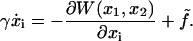
PcrA helicase from B. stearothermophilus has been crystallized and resolved at high resolution (8), in both a substrate (with ATP bound) and a product (without ATP/ADP bound) state. The structures, as shown in Fig. 1, were crystallized in the presence of a DNA junction, i.e., duplex DNA flanked by a piece of 3′ ssDNA, with the duplex bound to the side of domain 2B and an elongated piece of ssDNA crossing above the two RecA-like domains 2A and 1A. Domains 1A and 2A, conserved among a class of helicase-like proteins (2,9), are proposed to play the most essential role in the translocation. ATP binds into a cleft between domains 2A and 1A, the binding site being lined by amino acids that are highly conserved among SF1 helicases (5,9). Two of the motifs in the ATP binding site (Walker A and Walker B) are highly conserved among all ATPases. Indeed, superimposing the ATP binding pocket of PcrA helicase with that of F1-ATPase shows that the ATP binding sites have high structural identity, suggesting that a closely related ATP hydrolysis mechanism may be at work (17).
FIGURE 1.

Schematic view of a PcrA helicase-DNA complex with ATP bound (a) and without ATP/ADP bound (b). (Top, left) Shown are the protein domains (in cartoon presentation: red, 2A domain; green, 1A domain; blue, 2B domain; yellow, 1B domain) along with DNA (van der Waals presentation: red, oxygen; cyan, carbon; blue, nitrogen; tan, phosphorus; white, hydrogen); the duplex DNA is bound to the top left of PcrA and is flanked by a 3′ ssDNA that crosses through the middle of PcrA from left to right. (Top, right) Shown is an enlarged view of the ssDNA crossing through PcrA together with key amino acids. The DNA is shown in both licorice and (transparent) van der Waals (hydrogens not shown for clarity) presentation; amino acids (in licorice presentation) are color-coded (green, polar; white, nonpolar; blue, positively charged; red, negatively charged). Note that the DNA strand is negatively charged. (Bottom, right) The top figures are summarized into a schematic view highlighting the key elements, including the numbering of the ssDNA units (nucleotides) directly involved in binding. (bottom, left) The individual potentials of the two PcrA domains moving along ssDNA are introduced; the red and green disks correspond to the position of the domains 2A and 1A, respectively; the corresponding potential energy profiles are given in red and green; one can recognize that in the (substrate) state (a) with ATP bound, domain 2A is supposed to experience lower energy barriers than domain 1A, while in the (product) state (b) after ADP and phosphate dissociate, domain 1A is supposed to experience lower energy barriers than domain 2A. We use in this figure and other figures the one-letter code for amino acids.
The study reported in this article seeks to identify through a computational modeling approach the molecular mechanism underlying the fundamental function of helicase, the ATP hydrolysis powered unidirectional translocation along an ssDNA track. Such an approach was employed in previous studies, for example, in Chennubhotla et al. (18), Aksimentiev et al. (19), Ma et al. (20), and Wang and Oster (21) for molecular machines. PcrA helicase is selected here, since it is one of the smallest linear motors with full atomic scale structures available as well as experimental information on velocity and step size. The helicase system also involves protein-DNA interaction and recognition in a very confined space. Understanding the basic mechanism of PcrA helicase may facilitate understanding of more complex molecular motors.
Prior theoretical work investigated helicase function in a generic framework employing certain mathematical models that can describe helicase unwinding duplex DNA (22–24). This work proved very useful for this study, yet it postulated ad hoc the fundamental steps in helicase motor function, namely, different forward and backward translocation rates. The authors also addressed only generic helicases, not any particular one. In contrast, the present work seeks to establish the helicase motor mechanism from the structural and physical properties of a particular helicase, PcrA, the relevant physical properties being established through molecular dynamics (MD) simulations.
We based our study on the crystallographic structures reported in Velankar et al. (8) and mentioned above. We assume that the two structures, one with an ATP (analog) bound and one without ATP/ADP, present key states lying along the pathway of the PcrA translocation process. This is by no means certain since artifacts, in particular due to crystal packing, might shift the protein away from its mechanistically relevant conformations. The goal of our study was to identify through molecular dynamics simulations the mechanism of PcrA translocation. Two main translocation models had been discussed in the literature, an active rolling model, suggested actually for a dimeric helicase (25), and an inchworm model (26). As long as PcrA translocates as a monomer, the inchworm model is presently the only candidate. Our study assumes that PcrA works as a monomer and, hence, it focuses only on the inchworm model. This model was also proposed by the crystallographers who solved the structure of PcrA (8). According to the model, PcrA moves by alternating affinities between its translocation domains (2A and 1A) and ssDNA. So far, however, the inchworm model, while eminently insightful, was based on intuition, i.e., it is mainly qualitative and does not result from quantitative physical properties of PcrA derived from its crystallographic structures. Our study seeks to provide the missing physical basis for the inchworm model.
Experimental data showed that the translocation speed of PcrA along ssDNA is ∼50 nucleotides (nt) per second, presumably consuming one ATP for 1-nt distance (13). Based on this information, we propose a schematic model (see bottom left panels of Fig. 1, a and b), in which the substrate state exhibits lower energy barriers for domain movement of 2A along ssDNA (red curve) and higher ones for 1A (green curve), while the product state exhibits lower energy barriers for domain movement of 1A along ssDNA and higher ones for 2A; coupling these changes in mobilities to attraction (upon ATP binding) and repulsion (upon ADP+Pi dissociation) between the two domains leads to directed translocation. This model followed from the molecular dynamics (MD) simulations reported here, from which we derived the potential for individual domain (2A and 1A) motions along ssDNA as shown in Fig. 1. For this model we develop then a stochastic dynamics description of PcrA translocation. Our study suggests that the unidirectional translocation (3′ to 5′) of PcrA is a direct consequence of alternating high and low energy barriers experienced by 2A and 1A during each ATP hydrolysis cycle. Our work provides microscopic justification for the alternating affinities between domains and ssDNA proposed by the inchworm model (8).
In the following, we first introduce in Methods the stochastic model for the millisecond domain movements of PcrA. Then we describe a scheme to determine from MD simulations the potentials that govern the domain movements. The potentials obtained from MD simulations are provided in Results, followed by the demonstration that the potentials coupled to the ATP hydrolysis cycle lead to unidirectional movement. We finally identify the key amino-acid residues coordinating the unidirectional translocation in PcrA helicase, and provide further evidence for dynamic asymmetries of PcrA domains with bound ssDNA.
METHODS
Naturally, one would like to simulate the processive motion of PcrA along ssDNA entirely by MD simulations. Such simulations should employ nothing but the crystallographic structure of PcrA, heuristic information on atomic level interactions of biopolymers, and the laws of classical mechanics, i.e., the approach taken should be unbiased in regard to the translocation mechanism. Unfortunately, such an approach is computationally too demanding since MD simulations can cover at best microsecond timescales, i.e., they are at least a factor-1000 too slow for the present problem. To investigate the mechanism of PcrA we take a different route, approaching the description of PcrA from the short timescale by means of MD and from the long timescale by means of stochastic dynamics, both approaches being specified below. The stochastic dynamics method is based partially on results from short time MD simulations, partially on observed properties like ATP hydrolysis rate or PcrA translocation speed. This permits one to bridge the time gap between the MD description and the actual function of PcrA. In the following, we outline first the long-time stochastic dynamics approach and subsequently the short-time MD approach.
Stochastic dynamics description of PcrA translocation
Here we seek to describe the translocation of PcrA along ssDNA by means of stochastic dynamics theory. For this purpose, we will assume two limiting scenarios, expecting that the most realistic model falls between the two limits. We envision that the sliding of PcrA along ssDNA comes about through an inchworm motion involving separate, but coupled translocations of its 2A and 1A domains as suggested in Velankar et al. (8). Three factors govern the linked motion of domains 2A and 1A:
There exist geometrical constraints that forbid the domains to pass each other as well as to separate too far.
Binding of ATP favors a narrower separation between domains 2A and 1A while unbinding of ADP favors a wider separation between the domains (as revealed from the crystallographic structures).
Depending on the state of PcrA (substrate s/product p) the domains experience different effective potentials characterizing the energetics of individual domains translocating along ssDNA, e.g., in the ATP bound state (s) 2A can glide easily (low energy barriers) and 1A can hardly glide (high energy barriers).
Below we introduce two scenarios that demonstrate how 1–3 can endow PcrA with unidirectional motion.
The motion of domains 2A and 1A translocating along ssDNA (coordinates x1 and x2, respectively) is a stochastic process, that, on the relevant timescale, can be described by means of a Langevin equation in the strong friction limit (27,28),
 |
(1) |
Equation 1 holds in a particular state of PcrA, e.g., the s or p state. Here γ is the friction coefficient;  is the fluctuating force, represented through so-called Gaussian white noise (29,30); W(x1, x2) is the potential governing the movement of domains 1A and 2A along ssDNA; xi, i = 1, 2, are defined through
 |
(2) |
where  and
and  are the coordinates of the centers of mass of domains 1A and 2A along ssDNA, 〈⋯〉p denotes the average in the p state, and l0 is defined as 1-nt distance (∼6.5 Å). We note that −x defines the forward, i.e., toward the DNA junction, direction. The Langevin equation, Eq. 1, ignores possible memory effects; at this exploratory stage of the investigation the neglect of memory effects seems to be justified. The approach, of course, would be wrong for extreme memory effects, e.g., if translocation in step 1, 3, … follows a different mechanism from translocation in steps 2, 4, ⋯. The dynamics adopted ignores also hydrodynamic effects of the domain motions and translocation.
We define potentials, Uiσ(xi), governing individual (i = 1,2 for 1A and 2A, respectively) domain motions in the s and the p states (σ = s, p); the interaction potential between the two domains is written Vσ′(x1, x2) (σ′ = s, p). The values σ and σ′ are independent indices, i.e., below we will combine Uiσ and Vσ′ with different indices (states) σ, σ′. The value W(x1, x2) in Eq. 1, labeled by indices σσ′, is then decomposed into three contributions:
 |
(3) |
The individual potentials Uiσ(xi) are derived from MD simulations (described below) and are shown in insets of Fig. 2.
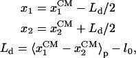
FIGURE 2.

Site energies of ssDNA units (nucleotides) and individual domain potentials for PcrA with ATP bound (a) and without ATP bound (b). Solid diamonds represent the relative binding free energies of ssDNA units, i.e., the weighted sum of electrostatic and vdW energies between protein and individual nucleotides, with the separate contributions indicated through open triangles and open pentagons, respectively. A smooth site energy function Eb(x) is drawn through the solid diamonds using a third-order polynomial interpolation (with the parameter δ = 0; see Supplementary Material). The corresponding positions of nucleotides are shown along x, the ssDNA path; i for each position xi labels the nucleotide. The inset shows the potential Uiσ(Δx) experienced by domain 2A (red solid curve) and 1A (green solid curve) as the domains move along ssDNA; the length scale is in units of 1-nt distance (6.5 Å). Uiσ(Δx), defined in the text, is derived from the site energy Eb(x) in the figure; the dashed line represents the difference between the green and the red curve.
In the first scenario, referred to as the weak coupling case, domains 2A and 1A move without interaction, i.e., we set Vσ′(x1, x2) = 0. Therefore, there are only two independent Langevin equations (Eq. 1) for the p and s states, respectively. Geometrical constrains (1) (see above) still apply, e.g., it holds that 0 < x1 – x2 ≤ l0; the condition is satisfied through reflection boundaries. Starting from the p state, once 1A gets close enough to 2A, e.g., x1 – x2 < l0/3, PcrA can change rapidly to the s state (ATP bound); starting from the s state, once 2A moves far enough from 1A, e.g., x1 – x2 > 2l0/3, PcrA can change back rapidly to the p state (no ATP/ADP bound).
In the second scenario, referred to as the strong coupling case, the domains are pulled together when ATP binds and then are pushed apart when ADP and Pi unbind by means of the interaction potential Vσ′(x1, x2). This potential is modeled through
 |
(4) |
where the force constant k adopts a value of 1 kBT/Å2, empirically determined from MD simulations; the equilibrium length lσ′ for σ′ = s, p is chosen as lp = l0 and ls < lp, e.g., ls = l0/3. The form of the potential in Eq. 4 is the simplest choice and has been adopted due to lack of more detailed information. To improve the description, one might sample intersubunit distances for both crystal structures, but such sampling is presently unfeasible given the expected microsecond-to-millisecond timescale of the domain motion.
As mentioned above, σ′ (in Vσ′) and σ (in Uiσ) are independent indices; hence combinations of them (in Wσσ′) can represent four different states. In the equilibrium substrate (or product) state σ = σ′ = s (or p) holds, which will be labeled ss (or pp). For σ = s and σ′ = p, the system is in transition from the equilibrium substrate to the product state. We will refer to the intermediate state as sp; similarly we call the intermediate state from the product to the substrate state ps (σ = p and σ′ = s). Correspondingly, there are four independent Langevin equations (Eq. 1) for these four states.
Transition from the pp state to the intermediate ps state is triggered by arrival of ATP and transition from the ss state to the intermediate sp state is triggered by the formation of ADP+Pi (through ATP hydrolysis). The two transitions happen at certain rates as specified below. For transitions from the intermediate ps or sp state to the equilibrium ss or pp state to happen, geometrical criteria were applied, such that ps transits to ss when the domain separation x1–x2 shrinks below ls while sp transits to pp as x1–x2 elongates beyond lp.
The Langevin equation (Eq. 1) can be solved numerically (28) when one assumes discrete time-steps Δt, adopting the scheme
 |
(5) |
Here Z is a normal (Gaussian) random variable (29) (with mean 0 and variance 1); D is the diffusion coefficient, according to the fluctuation dissipation theorem (30) related to the friction coefficient γ through D = kBT/γ; and D is expected to assume a value ∼104 Å2/μs (corresponding to a typical diffusion coefficient of a 3 nm-radius protein in solution (27)). Coupling between equations is achieved through a random process which we describe now.
In case of weak coupling, the transitions between states s and p (right after the domain motion) are assumed to be fast compared to the domain motion described by Eq. 1. Once x1–x2 satisfies the criteria for state transitions mentioned above, transitions are induced through a Poisson process using rate constants specified below. In the strong coupling case, the transitions between states ss and sp or between states pp and ps are assumed to be slow compared to the stochastic motion in Eq. 1 and are also described through a Poisson process with rate constants specified below. Poisson processes are simulated by generating uniformly distributed random numbers Y (Y ∈ [0,1]) and adopting the transition in the case Y ≤ ωΔt (ωΔt ≪ 1), where ω is the rate constant for the transition and Δt is the discrete time step in Eq. 5.
The stochastic method adopted is related to the so-called kinetic and dynamic Monte Carlo scheme widely adopted in physics and chemistry (31–34). The simple choice of reaction coordinate x (path along ssDNA) could be improved by determining a reaction coordinate accounting for the forward reptation of ssDNA in PcrA by means of a so-called reaction path method (for a review see (35)), e.g., the ones suggested in Elber (36) and Straub (37).
Nucleotide binding site energies and the site energy function
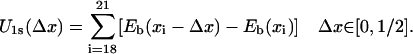
A key task in our study is the derivation of the potential Uiσ(xi) in Eq. 1, governing the movement of domains 1A and 2A. Since the translocation of helicase along ssDNA arises through ssDNA units (nucleotides) binding and unbinding sequentially to the domain surfaces, one strategy for determining the potential is to calculate the binding free energies Eb for individual nucleotide binding sites and then use these energies to obtain Uiσ(xi). The calculation of the binding free energy from MD simulations can be achieved by a method (38,39) which is based 1), on the linear response approximation for electrostatic forces; and 2), on linear scaling between solvation energies and average van der Waals (vdW) energies. The method evaluates the absolute free energy solely from the difference between the average interaction energy between nucleotide and protein+water+ion (bound state) and the average interaction energy between nucleotide and water+ion (free state). The value Eb, for a given binding site located at xi, is given as a weighted sum of the electrostatic and the vdW interaction energy,
 |
(6) |
with weight coefficients α and β discussed further below. Here Δ denotes the difference between average energies (stemming from simulations) of the bound and the free states, i.e.,
 |
(7) |
In the present case, we will need only relative energies, not absolute ones, e.g., Eb(xi) − Eb(xj). Since, in the free state (nucleotides with water + ion, but without protein), the nucleotide-solvent interaction energies Eele/vdW(free, xi) should not vary along ssDNA (poly-thymine), i.e., be independent of xi, it is not necessary to actually calculate Eele/vdW(free, xi) and we set these energies to zero. We introduce a further approximation in evaluating Eele/vdW(bound, xi). For this purpose we split the energy terms as follows:
 |
(8) |
For nucleotides buried inside PcrA, we assume that the contributions  are independent of xi; therefore, we also set these energies to zero and count only nucleotide-protein interactions in evaluating Eb(xi). On the side of the protein all amino acids were added in calculating the relevant energies.
The weight coefficient α in Eq. 6 was shown to be 0.5 (38,39) while β could adopt values from 0.15 to 1.0, depending on the hydrophobicity of the binding sites (the more hydrophobic a site, the larger β) (40). Since the (ssDNA) nucleotide binding sites are buried inside the protein, i.e., are less exposed to water, we adopted β = 1.0 (slight variation of β does not affect our major conclusions). The energies Eele and EvdW were calculated (with a cutoff distance of 60 Å) from MD trajectories, sampling every 100 ps and averaging over 2 ns, beginning after the first 1 ns of equilibration.
The weighted sums of Eele and EvdW for individual ssDNA nucleotide binding sites, calculated according to Eq. 6, are presented in Fig. 2 by discrete site energies Eb(xi), where xi, i = 15/14 (in s/p), …, 21, are positions of corresponding nucleotides (numbered in the same way as in Fig. 1). To relate the energies Eb(xi) to a process in which ssDNA nucleotides move collectively, in a continuous way, across the surface of domain 1A or 2A, one needs a continuous site energy function Eb(x) connecting the discrete Eb(xi) values, x being the path length along an imaginary line going along the backbone of the ssDNA bound by PcrA. Since the Eb(xi) should represent energy minima or at least marginally stable points for the ssDNA nucleotides, the functional values of a continuous energy function Eb(x) between points xi represent the roughness of the energy surface, the roughness determining the overall speed of ssDNA motion and, hence, of PcrA. The roughness effect can be adjusted effectively at a later stage of the calculation (through a parameter δ, see Eq. 13) and, hence, we assume Eb(x) to be represented by a smooth curve interpolating the Eb(xi) values. Accordingly, Eb(x) was constructed using a third-order polynomial interpolation; the construction scheme is detailed in Appendix A. The resulting curve is shown in Fig. 2. As one can see, the construction assigns to the boundary sites (exposed to solvent) x15/x14 (in s/p) and x21 equal energy values.
The interpolation scheme constitutes a significant assumption in our description. One may suggest to replace Eb(x) by a potential of mean force derived through umbrella sampling (41) or steered MD (SMD) (42) linked to use of the Jarzynski identity (43,44). However, such an approach is unfeasible because of the complex degrees of freedom orthogonal to x; these degrees of freedom might participate also very specifically in the translocation, e.g., through base flipping—requiring then a new reaction coordinate and in any case, would be slow to relax.
Potentials governing individual domain motions along ssDNA
With the knowledge of Eb(x) one can estimate the potentials Uiσ(xi) governing individual motions of individual domains. We assume that PcrA translocates during one ATP hydrolysis cycle one nucleotide (nt) as suggested by experiment (13). Then the total energy of PcrA moving along ssDNA (to which Uiσ is but one contribution) should have period-one (1-nt distance); we will impose, however, the more stringent condition that both U1σ and U2σ have period-one.
We want to estimate now Uiσ from the binding energies Eb(x) considering first the s state. When domain 2A moves forward (to the left in Fig. 1 a), nucleotides 19 and 20 (and those beyond 20) remain in the same binding sites; however, nucleotide 15 will move toward 16, 16 toward 17, then 17 toward a new site, A (which would be occupied by 17 in the p state; see Fig. 1 b), and 18 will move toward another new site, B (which would be occupied by 18 in the p state; see Fig. 1 b), anchored into the pocket formed by side chains Tyr-257 and Phe-64. The potential energy governing this motion of 2A, U2s, is equal to the sum of site energy differences connected with moving nucleotides 15, 16, 17 and 18 (and those beyond 15, which along with 15 are assumed to be of equal energy) backward, as indicated by colored arrows in Fig. 2. This energy is
 |
(9) |
In our description we assume that U2s(Δx) adopts a symmetrical form around Δx = 1/2, the position of an energy barrier separating the states before (Δx = 0) and after (Δx = 1) an ATP hydrolysis half-cycle. This assumption also applies to other Uiσ(Δx) derived below.
Now we can determine the boundary energy at site x15. The emergence of the two new sites at Δx = 1 (as the system moves to the p state), A and B, arises effectively from the disappearance of the middle site at x18 and the boundary site at x15; therefore, it holds that  , with
  and
and  being the (unknown) binding energies at sites A and B, respectively. Since A and B are sites close to x17 and x18,
  might be approximated by Eb(x17) + Eb(x18); the periodicity condition U2s(0) = U2s(1) = 0 thus yields Eb(x15) = Eb(x17).
One can apply a similar reasoning to the backward (to the right in Fig. 1 a) motion of domain 1A and derive Eb(x21) = Eb(x17). In this case, nucleotides 16 and 17 (and those to the left beyond 16) will occupy their original binding sites while nucleotide 21 moves toward 20, 20 toward 19, 19 toward the new site B, and 18 toward the new site A. Thus, one can conclude
 |
(10) |
Similarly, we consider the energies for the p state, i.e., Uip. When domain 2A moves backward (to the right in Fig. 1 b), nucleotides 19, 20 … remain at the same binding sites while nucleotide 15 moves toward 14, 16 toward 15, 17 toward 16, and 18 toward the new site C (which was occupied by 18 in the s state, see Fig. 1 a). Following the reasoning for the s state above, the energy U2p(Δx) is
 |
(11) |
The periodicity condition  stipulates
  . With
  approximated by Eb(x17), this gives Eb(x14) = Eb(x18). For a similar reason this condition applies also to the case that domain 1A moves forward with its energetics described by U1p. In that case, nucleotides 15, 16 occupy their original binding sites while nucleotide 17 moves toward the new site C, 18 toward 19, 19 toward 20, and 20 toward 21. The energy is
 |
(12) |
Combining the definitions of Uiσ(Δx) above, i.e., Eqs. 9–12, it can be recognized that each barrier Aiσ, defined as Uiσ(Δx) at Δx = 1/2, can be written
 |
(13) |
where Σiσ is a combination of site energy terms, stated explicitly in Eq. 14. The site energies terms are determined from MD simulations as explained above. We add here a term 4δ that controls the speed of PcrA translocation, i.e., ∼1 nt per 20 ms, consistent with observation (13). The relationship of δ, which is chosen identical for both domains (i = 1, 2) and for both states (σ = s, p), to the energy surface roughness (energy undulations) of Eb(x), is stated in Appendix A.
We emphasize that the construction and later use of the potentials Uiσ(x) hinges on particular motions of ssDNA along the domains as specified above. If the actual translocation would involve different behavior of ssDNA, the description adopted here would be called into question. The results of our study should be interpreted as proving the feasibility of the inchworm model once it is assumed.
Molecular dynamics simulations
Starting from the crystal structures of the PcrA helicase in the s (PDB code 3PJR) and p (PDB code 2PJR) state (8), we added missing residues in the protein as well as elongated both duplex DNA and ssDNA (poly-T). The ssDNA was elongated by first opening, i.e., swiveling by 30°, the 2B domain (45), adding the corresponding piece of ssDNA (five nucleotides) from the structurally homologous Rep complex (PDB code: 1UAA) (45) to the end of the original ssDNA, then swiveling the 2B domain back to its initial position by means of SMD (42), and letting the elongated ssDNA segment relax to fit to the PcrA domains.
The structures of the PcrA-DNA complex were solvated in a box of explicit water. Sodium, magnesium, and chloride ions were added to neutralize the negative charges of the PcrA-DNA complex and to control the ionic strength (0.1 M). The program Delphi (46) was used to locate positions of minimal electrostatic energies around the complex, where the water molecules were then replaced by ions. The whole simulated system of protein, DNA, water, and ions contained ∼110,000 atoms.
All simulations used the program NAMD2 (47), the CHARMM27 force field (48), with an integration time step of 1 fs, and periodic boundary conditions. VdW energies were calculated using a smooth (10–12 Å) cutoff. The particle-mesh Ewald method (49) was employed for full electrostatics, with the density of grid points at least 1/Å in all cases. The particle-mesh Ewald electrostatic forces were computed every four time steps. The simulations were performed in the NpT ensemble, using the Nośe-Hoover Langevin piston method (50,51) for pressure control (1 atm), with an oscillation period of 100 fs and a damping time of 50 fs; Langevin forces (52) were applied to all heavy atoms for temperature control (310 K) with a coupling coefficient of 5/ps.
To verify the relationship between barrier heights of individual domain motions, i.e., A2s < A1s and A2p > A1p, which were derived from equilibrium MD simulations, we carried out an independent set of SMD simulations pulling ssDNA one half-step (∼3 Å, corresponding to Δx = 1/2 in Eqs. 10–13) forward and backward along the ssDNA binding interfaces of 2A/1A in both the s and p states. For this purpose, we attached 10 harmonic springs (force constants of 2 kcal/mol Å2) to 10 phosphorous atoms of ssDNA, and pulled the ends of the springs with a constant velocity of 3 Å/ns. The SMD methodology is explained and reviewed in Isralewitz et al. (42), Izrailev et al. (53), and Sotomayor et al. (54). Each pulling simulation was repeated four times and measurements of SMD forces were averaged over the four trajectories. Sample movies of the SMD simulations are provided in Supplementary Material.
To estimate the force constant k arising in the interaction potential, Eq. 4, we monitored in our MD simulations the fluctuations of the distance L between the center of mass of two groups of atoms that represent the edges of domains 2A and 1A. We chose for these groups a helix segment (residues 369–374) from domain 2A and a helix segment (residues 76–81) from domain 1A. The MD simulations revealed a standard deviation δL ∼ 1Å in both s and p states. According to the Brownian oscillator relationship k = kBT/δL2 we estimate k ∼ 1 kBT /Å2. The simulation data are provided in Supplementary Material.
RESULTS AND DISCUSSION
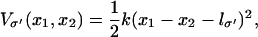
Equilibration by MD simulation
The simulated system of the solvated PcrA-DNA complex is shown in Fig. 3 a. Each MD equilibration (substrate, s, and product, p), started after 5000 steps of energy minimization and lasted for ∼3 ns. The root mean-square deviation curves for backbone atoms of protein and DNA during each equilibration are shown in Fig. 3, demonstrating that the system was more or less stabilized after 1 ns.
FIGURE 3.

Equilibrium MD simulations of the PcrA-DNA complex. The simulation system is shown on the left, with the PcrA-DNA complex (protein in dark blue, DNA in magenta) solvated in an explicit water box (light blue), together with ions (sodium in yellow, magnesium in green, and chloride in light blue); ATP, colored in red, is present in the system. Shown on the right are the root mean-square deviation value of protein and DNA backbone atoms with (top) and without (bottom) ATP bound.
The equilibrated configuration of double-stranded DNA is more regular and less distorted by the helicase in the s state than that in the p state (see Fig. 1), as evidenced by fewer contacts between double-stranded DNA and domain 2B in the s state. The binding between the translocation domains and ssDNA is illustrated in enlarged views in Fig. 1. One can recognize that nucleotide 18 points its base upward in the s state (Fig. 1 a) and downward into a binding pocket in the p state (Fig. 1 b). The pocket, formed by the side chains of Phe-64 and Tyr-257, is closed in the s state and open in the p state.
By monitoring an angle formed by two protein helices, residues 360–374 from 2A and residues 66–81 from 1A, during equilibration, it was found that the ATP binding cleft in-between domain 2A and 1A is ∼10° wider in the p state than in the s state. The opening and closing of the ATP binding cleft in different states (binding of ATP favors a narrower separation between domains 2A and 1A while unbinding of ADP and Pi favors a wider separation between the domains) turn out to be the most important structural feature directly supporting the PcrA translocation, as discussed below.
Potentials Uiσ from MD simulation
Utilizing the equilibrium MD trajectories, we obtained the binding energies Eb(xi) of individual ssDNA nucleotides. The results, based on Eq. 6, are shown in Fig. 2 for the s and the p state, specifying both the electrostatic and the vdW contributions. It can be recognized that electrostatic energies, only due to the protein, differ significantly for individual nucleotides between s and p states, whereas the vdW energies do not. The standard deviation of the average value of the electrostatic (vdW) energy for each nucleotide is ∼2–4 kcal/mol (0.5 kcal/mol). For each state, the continuous site energy function Eb(x) (also shown in Fig. 2) connecting the discrete binding free energy values was constructed.
Eb(x) permits one to derive the potential Uiσ(xi) governing the motion of individual domains along ssDNA (see Eqs. 9–12). The potential Uiσ(Δx) is shown in the insets of Fig. 2. One can recognize that in the s state the barrier height (A2s) in the potential U2s for 2A motion is lower than the barrier (A1s) in U1s; the opposite is true in the p state. The barrier heights Aiσ can be expressed explicitly in terms of the site energy differences of nucleotides
 |
(14) |
where δ is a tunable parameter (see Appendix A). Although the barrier heights Aiσ individually depend on δ, the difference between barrier heights of competitive (1A vs. 2A) domain motions in each state is independent of δ, i.e., the value A1s – A2s ∼9 kcal/mol in the s state and A2p − A1p ∼12 kcal/mol in the p state are independent of δ. The difference between barrier heights actually governs the timescale separation between the competing domain motions. From Eq. 14, one can recognize that A2σ − A1σ, after canceling identical terms in A2σ and A1σ, is determined by energy imbalances (combined energy differences between neighboring sites) among some specific nucleotide binding sites, which are indicated in Fig. 2.
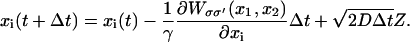
This difference between barriers A2σ and A1σ for domain motions is a key result of our study and was verified by us. In our analysis we accounted only for protein-DNA interactions without explicit solvent contributions. To partially verify the result we carried out an independent set of SMD simulations (sample movies of the SMD simulations are provided in Supplementary Material), pulling ssDNA one half-step forward and backward, along the protein-ssDNA interface across the helicase domains. The forces needed to pull the relevant nucleotides were monitored and are reproduced in Fig. 4. The results show that in the s state, the average force needed to move nucleotides 15–18 rightward (corresponding to 2A motion toward the left) is smaller than that needed to move nucleotides 18–21 leftward (corresponding to 1A motion toward the right); vice versa, in the p state, the average force needed to move nucleotides 15–18 leftward (corresponding to 2A motion toward the right) is larger than the force to move nucleotides 17–20 rightward (corresponding to 1A motion toward the left). This is consistent with the Uiσ(Δx) potentials shown in Fig. 2. We note that the SMD simulations took into account interactions of ssDNA with both protein and solvent (water/ions) as well as the short time part of the entropic effect.
FIGURE 4.

Comparisons of SMD forces arising in ssDNA pulling simulations in PcrA with ATP bound (a) and without ATP bound (b). The green/red curve represents the average force needed to move relevant nucleotides (indicated by green/red arrows), corresponding to the movement of domain 1A/2A in the opposite direction. The thin curves were measured directly from simulations, while the thick curves were smoothed over every 10 data points. The results show that in panel a, the average force needed to shift the relevant nucleotides, corresponding to the domain movement of 2A, is smaller than the average force needed to shift the relevant nucleotides corresponding to the domain movement of 1A; the opposite is true in panel b.
Langevin dynamics of PcrA translocation in two scenarios
The goal of our study is to explain the physical mechanism underlying the unidirectional translocation of PcrA along ssDNA. Individual translocation steps per ATP hydrolysis require ∼20 ms (13). Our MD simulations cover, however, only nanoseconds. As explained above, the timescale gap can be overcome through a stochastic, i.e., Langevin, dynamics description that builds on the potentials Uiσ (see Eq. 3 and 9–12) estimated from the MD simulations. As explained in Methods, we simulated the millisecond domain movements of PcrA through Eq. 1 in corresponding states employing the potential function defined in Eq. 3. In case of the weak coupling scenario we choose for Vσ′ a vanishing potential; in case of the strong coupling scenario, we describe Vσ′ through Eq. 4. Our description includes random transitions between states. The results of this description are provided in Fig. 5.
FIGURE 5.

Langevin simulation of ssDNA translocation in PcrA in the weak coupling scenario (a) and in the strong coupling scenario (b). (Left) Shown are trajectories of the two domains, 1A (green) and 2A (red), moving along ssDNA; the time is given in units of ATP hydrolysis cycles (one cycle is ∼20 ms). (Right) Illustrated are the individual potentials Uiσ experienced by domain 1A (green) and domain 2A (red) moving along ssDNA in different states (p, s or pp, ps, ss, and sp defined in Methods), or configurations (1′, 2′, 3′, and 4′, which are defined for the convenience of later discussions; see Fig. 6). Transitions which do not involve domain movements (and are simulated by a Poisson process; see Methods) are labeled by double arrows in both scenarios. In the weak coupling scenario, two domains are shown as being connected by a rod, corresponding to the geometric constraint; in the strong coupling scenario (b), the domains are shown as being connected by an elastic spring with variable equilibrium lengths, corresponding to the nonvanishing interaction Vσ′.
Weak coupling scenario
This case is presented in Fig. 5 a. The left panel of Fig. 5 a shows the stochastic trajectories of domains 2A and 1A along ssDNA. Over the period of 10 hydrolysis cycles, i.e., 200 ms, the positions of 2A and 1A change by ∼70 Å, reflecting 11 translocation steps with variable durations (due to the stochastic nature) in between. One can recognize that the domains move in a nearly synchronous fashion along the −x-direction (see movie provided in Supplementary Material). Underlying this motion is the scenario shown in the right panel of Fig. 5 a. The system traverses sequentially configurations 1′ → 2′ → 3′ → 4′ → 1″ as identified in the figure. The configurations are also identified through state labels p and s, introduced earlier. In configuration 1′, PcrA is in the p state, domains 2A and 1A are separated by 1-nt distance and move according to potentials U2p and U1p, respectively; 1A experiences a low barrier and can move readily, while 2A experiences a high barrier and is essentially stuck. When 1A has moved forward (to the left) close enough to domain 2A (e.g., by l0/3, see Methods) it reaches configuration 2′. In this configuration the system has a high probability to transit to the s state (in reality this corresponds to the approach of domains 2A and 1A, leading to an optimal binding geometry for ATP), reaching configuration 3′. In the s state, however, the potentials U2s and U1s differ qualitatively, in that now 2A is easy to move and 1A becomes stuck. When 2A moves forward (to the left) far enough from domain 1A (e.g., by 2l0/3), PcrA reaches configuration 4′. In this configuration the system has a high probability of transiting to the p state (this corresponds to ATP hydrolysis/dissociation of ADP and Pi), reaching the configuration 1″. Since PcrA has now moved 1-nt distance to the left compared to the original configuration 1′, we denote the new configuration by 1″.
In the weak coupling scenario, the barrier-crossing domain movements (governed solely by potential Uiσ) are assumed rate-limiting. The barrier heights in configurations 1′ and 2′ assume the values A2p = 24.7 kcal/mol, A1p = 12.8 kcal/mol and in configurations 3′ and 4′ assume the values A2s = 10.7 kcal/mol, A1s = 19.4 kcal/mol (see Eq. 14). The values were chosen through their δ-dependence in Eq. 14 (δ = −0.62 kcal/mol) such that the simulated speed of translocation agrees with the observed speed (13).
Strong coupling scenario
The random motion of PcrA along ssDNA in the strong coupling scenario is presented in Fig. 5 b. The left panel of Fig. 5 b presents the corresponding stochastic motions of domains 2A and 1A. The motions are qualitatively similar to those in the weak coupling case. Over the period of 10 hydrolysis cycles the positions of domains 2A and 1A change by ∼65 Å, reflecting 10 translocation steps. One can recognize again that the domains move in a nearly synchronous fashion toward the −x-direction (see movie provided in Supplementary Material). The scenario underlying this motion is shown in the right panel of Fig. 5 b. The system traverses again sequentially configurations 1′ → 2′ → 3′ → 4′ → 1″ as identified in the figure. The configurations are also characterized through state labels pp, ps, ss, and sp introduced earlier. In configuration 1′, PcrA is in the pp state, domains 2A and 1A are separated by 1-nt distance (lp in Vp, see Eq. 4), and are both essentially “stuck” in potential Uip exhibiting high barriers. Arrival of ATP for binding leads to configuration 2′ and the intermediate ps state. In this state, domains 2A and 1A experience the interaction potential Vs (corresponding to a harmonic spring, with ls ≤ lp) while individual potentials Uip maintain the pp state form. As a result, 1A experiences a lower barrier (combination of U1p and Vs) and can move readily; 2A also experiences a reduced barrier, but a higher one than 1A and still remains stuck. As Vs quickly draws the domains 2A and 1A close to each other (through the motion of 1A, but not 2A), PcrA relaxes to the 3′ configuration that corresponds to the ss state. In this configuration, both domains are stuck by Uis exhibiting high barriers. In the 3′ configuration, ATP hydrolysis can take place. Once this happens and the hydrolysis products ADP and Pi start dissociating, configuration 4′, corresponding to the sp state, is reached. In configuration 4′ the interaction potential changes from Vs back to Vp while individual potentials Uis retain the prior form. As a result, domain 2A experiences a lower barrier (combination of U2s and Vp) and can move readily; 1A also experiences a reduced barrier, but a higher one than experienced by 2A, and remains stuck. The relaxation of PcrA under Vp moves 2A to the left and brings the system back to configuration 1′. However, since PcrA has now moved 1-nt distance to the left compared to the original configuration 1′, we denote the new configuration by 1″.
In the strong coupling scenario, the barrier-crossing domain movements (under potential Uiσ and Vσ′) are not rate-limiting. In the present case, the transitions 1′ → 2′ and 3′ → 4′ corresponding to the arrival of ATP and occurrence of ATP hydrolysis are assumed to be much slower than the domain motions and, therefore, are rate-limiting for the overall translocation process. This provides us with more leeway in the choice of the barriers Aiσ. In fact, δ-values in the range between −1.2 and 0.4 kcal/mol give reasonable Aiσ values such that translocation occurs with a speed consistent with observation (13). We used δ = 0 kcal/mol, which gives barrier heights A2s = 13.2 kcal/mol, A1s = 21.9 kcal/mol, A2p = 27.2 kcal/mol, and A1p = 15.3 kcal/mol (see Eq. 14).
The intrinsic mechanism of unidirectional translocation
Fig. 5 demonstrates that both suggested PcrA translocation mechanisms, involving weak coupling and strong coupling, lead to unidirectional motion along ssDNA. This behavior is described through the solution of coupled Langevin equations. Here we seek an alternative description in terms of rate equations that provide a more systematic explanation for the unidirectional PcrA translocation as well as a convenient mathematical formulation to represent the associated translocation velocity. Our approach is closely related to the generic description developed in Betterton and Jülicher (23). We account for the motion of PcrA in terms of the average position x of its two domains 1A and 2A, defining x = (x1 + x2)/2. The description needs to also attribute to the moving PcrA the various states and configurations underlying the translocation process. These states and configurations are defined for both scenarios in Fig. 5 (right panels). The linking between x and states/configurations is presented in the schematic diagram in Fig. 6, again separately for the two scenarios. We begin with Fig. 6 a, which shows the weak coupling scenario (see Fig. 5 a). The figure places the states/configurations along the position axis. The states correspond to discrete values of position x, namely  . For the sake of better presentation, the states/configurations are arranged in two tiers, I and II. The correspondence with the configurations 1′, 2′, 3′, 4′, 1″ in Fig. 5 a is indicated in Fig. 6 a: 1′ corresponds to point (j, I), 2′ to point (
 , I), 3′ to point (
 , II), 4′ to point (j – 1, II), and 1″ corresponds to point (j – 1, I). The configurations capture the cyclic translocation dynamics of PcrA and repeat themselves along the position axis. For example, configuration 1″, located at (j – 1, I), is shifted by one unit along the position axis from configuration 1′. The translocating PcrA cycles through the states/configurations by undergoing transitions between them. The transitions are indicated in Fig. 5 a and include, for example,
  ,
,  ,
,  , and
, and  . The transitions will be described mathematically by linear rate equations and associated rate constants. The rate constants r1, r2 (s1, s2) correspond to the forward (backward) motion of domains 1A and 2A, respectively (we note that the forward direction in Fig. 6 is to the left); transitions starting from tier I and II to the other are described by rate constants ωI, ωII; reverse transitions are denoted by primes, e.g., r′1 and ω′II. In the weak coupling scenario the transitions denoted by ωI, ωII, i.e., transitions that do not translocate PcrA, are fast relative to the transitions that do translocate PcrA; this is also indicated in Fig. 6 a. The latter transitions are governed by the potentials Uiσ. The corresponding energy barriers are drawn in Fig. 6 a to indicate which transitions are feasible (only those connected with low barriers).
FIGURE 6.

Schematic energetics of PcrA translocating along ssDNA in the weak coupling scenario (a) and in the strong coupling scenario (b). Shown schematically are total energy profiles (in both I and II) projected along the position of PcrA (average position of domain 2A and 1A) on ssDNA in units of l0, i.e., one-nt distance (∼6.5 Å). Configurations 1′, 2′, 3′, 4′, and 1″ (see Fig. 5), etc., and transitions connecting these configurations as well as the associated rate constants are labeled (see text for detail). Fast and slow steps in each scenario are also denoted.
As stated in Table 1, the average time for the transition 1′ → 2′, which corresponds to domain 1A moving forward and is governed by potential U1p, i.e., 1/r1, is estimated in Appendix B to be ∼19 ms; the average time for the transition 1′ → 2, which corresponds to domain 2A moving backward, i.e., 1/s2, is estimated likewise to be ∼106 s. We note that 1A, in principle, can move both forward and backward facing the same low barrier height; however, due to the geometric constraint (x1 – x2 ≤ l0, see Methods), 2A and 1A cannot be separated too far and since the initial separation between 2A and 1A in configuration 1′ is large (x1 – x2 ∼ l0), only the forward motion of 1A is allowed. Values for transition rates (times), 1/r2 and 1/s1, are also stated in Table 1. One can recognize that 1/r1 + 1/r2 assume a value of ∼20 ms as we fit it to the observed speed (13). The values r′i and s′i (i = 1, 2) are not listed and they assume the same values (in the weak coupling scenario) as ri and si, respectively. The transition rates between tiers I and II are unknown in this case; however, since the transitions denoted by ωI and ωII are relatively fast, i.e., 1/ωi ≪ 20 ms (i = I, II), and should be much faster than the reverse transitions (primed), we concluded ωi ≫ ω′i and used 1/ωi = 100 ns and ω′i = 0, accordingly.
TABLE 1.
Transition times estimated for PcrA translocation in two limiting scenarios
| Time | Physical correspondence | Weak coupling | Strong coupling |
|---|---|---|---|
| 1/r1 | 1A moving forward | 19 ms | 0.3 ms |
| 1/s2 | 2A moving backward | 3 × 10⁶ s | 4 × 10⁴ s |
| 1/r2 | 2A moving forward | 0.8 ms | 0.03 μs |
| 1/s1 | 1A moving backward | 6 × 10² s | 14 ms |
| 1/ωI | No domain movement | 100 ns (assumed) | 15.4 ms |
| 1/ωII | No domain movement | 100 ns (assumed) | 4.6 ms |
The corresponding domain movements (or lack of movement) of the associated transitions are stated.
We now consider the strong coupling scenario depicted in Fig. 6 b. The presentation is analogous to that for the weak coupling scenario; the numbering of configurations corresponding to Fig. 5 b (right panel) is: 1′ corresponds to point (j, II), 2′ to point (j, I), 3′ to point ( , I), and 4′ to point (
 , II). However, in this case the domains experience an interaction described by Vσ′(x1, x2), which leads to an important variation. After transition 1′ → 2′, corresponding to the arrival of ATP, domains 2A and 1A are still separated (by lp = l0) while the potential Vs(x1, x2) with a short equilibrium length (ls = l0/3) is switched on, placing the system in an energized state. This is depicted in Fig. 6 b by placing configuration 2′ upwards on the energy profile by ΔE ∼ k(lp – ls)2/2. Likewise, configuration 4′, corresponding to PcrA with ATP just hydrolyzed, is depicted in an upward position on the energy axis again by ΔE, where domains 2A and 1A are close while the potential Vp(x1, x2) with a large equilibrium length (lp = l0) is switched on. Therefore, the transitions 2′ → 3′ and 4′ → 1″, which correspond, respectively, to domain 1A and 2A moving forward, are energetically favorable and happen fast.
The associated rate constants (times) for the transitions involving domain movements in Fig. 6 b are also provided in Table 1, with the values estimated in Appendix B. The primed rate constants, not shown in the table, are estimated as in Betterton and Jülicher (23): r′i = ri exp(−ΔE/kBT) and s′i = si exp(−ΔE/kBT), thus r′i and s′i (i = 1, 2) assume much smaller values than ri and si. For transitions between tiers I and II (not involving domain movements), ω′I = ωI is used assuming an isoenergetic transition  (55). We use ω′II = ωI for simplicity; ω′II and ωII are related by ωII = ω′II exp(μ – 2ΔE/kBT) due to the free energy changes, where μ is the chemical energy generated in one ATP hydrolysis cycle (with μ = 20 kBT used). Since now the transitions between tiers I and II are rate-limiting, 1/ωI + 1/ωII has to assume a value of 20 ms according to the observed translocation speed (13).
The transitions shown in Fig. 6 capture the coupling of ATP binding and hydrolysis/dissociation to the translocation of PcrA. The transitions can be cast into a rate equation that describes the probabilities of finding PcrA in the configurations 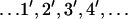 shown in Fig. 6 . For example, in the strong coupling scenario, the rate equation of the associated probabilities P1′, P2′, etc., reads (
 ),
),
 |
(15) |
as can be verified from inspecting Fig. 6 b. The quantities Jμν with μ, ν = 1′, 2′, etc., are probability fluxes defined through
 |
(16) |
The fluxes obey the property Jμν = – Jνμ. Here  are rate coefficients that can be identified from Fig. 6. For example, in the weak coupling scenario
  and
and  (= 0).
The rate equation can be cast into the form
 |
(17) |
where P is the infinite-dimensional probability vector (written here in transposed form),
 |
(18) |
(we assume for the sake of simplicity that the ssDNA is infinitely long). K is a matrix of rate coefficients that can be established from Eqs. 15 and 16. As often done in solving kinetic equations, we actually describe the steady state of translocating PcrA, which is characterized through  . For such steady state, the probability vector (18) should assume a spatially periodic form, namely
 |
(19) |
The probabilities  obey then the four-dimensional linear equation
 |
(20) |
as well as the condition P1 + P2 + P3 + P4 = 1. The matrix M is
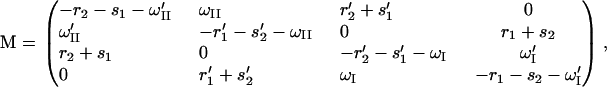 |
(21) |
which follows from Eqs. 15 to 17. A solution for Eq. 20 exists since the condition det M = 0 is satisfied (the sum of the rows of M vanishes). The unique (null space of M has dimension 1) solution can be obtained through a numerical algorithm as provided, for example, in the Mathematica (56) package.
One can now determine the translocation velocity of PcrA along ssDNA. For this purpose we note first that the stationary condition gives the identities J3″2″ = J2″3′ = J3′2′ = J2′3 = J32… = JI and J4″1″ = J1″4′ = J4′1′ = J1′4 = J41… = JII. This is because, in the steady state, the probabilities PT in Eq. 19 are translational invariant along ssDNA; the flux Jμν, which is only a combination of probabilities according to Eq. 16, should also be translational invariant. The corresponding translocation velocity is v = l0(JI + JII) (28). One can obtain, e.g., using a symbolic programming language like Mathematica (56), an explicit expression for v in terms of the rate constants shown in Fig. 6, a and b. One finds
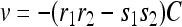 |
(22) |
where C is positive; its analytic form is given in Appendix C.
The previous calculations provide both the probabilities to find PcrA in the configurations 1–4 as well as the translocation velocity v. For the weak coupling scenario we determined the numerical values (P1, P2, P3, P4) ∼ (0.85, 0.0, 0.15, 0.0), implying that 85% of the time PcrA is in configuration 1 and 15% of the time it is in configuration 3 (see Fig. 5 a); configurations 2 and 4 are short-lived transition states. This behavior, i.e., that the system is predominantly in configuration 1 (equilibrium product state p), can be recognized in Fig. 5 a (left panel) as well as in a movie (showing the actual Langevin dynamics description) supplied in Supplementary Material. The calculated velocity is v ∼ 6.5 Å/20 ms, a value that results from adjusting the δ-parameter appropriately.
In the strong coupling case the probabilities for the configurations 1–4 defined in Fig. 5 b are (P1, P2, P3, P4) ∼ (0.23, 0.01, 0.76, 0.0), implying that 76% of the time PcrA is in configuration 3 and 23% of the time it is in configuration 1. This behavior, i.e., that the system is predominantly in configuration 3 (equilibrium substrate state ss) can be recognized also in Fig. 5 b (left panel) as well as in a movie (showing the actual Langevin dynamics description) supplied in Supplementary Material. The calculated velocity is again v ∼ 6.5 Å/20 ms, since it resulted again from the adjustment of the δ-parameter.
Although the numerical value of v stems from the choice of δ, the analytical expression for v, given in Eq. 22, reveals that the direction of translocation depends on the rates r1, r2, s1, s2 through the factor −(r1r2 – s1s2) (negative velocities correspond to the forward direction). The rate constants r1, r2, s1 and s2, denoted in Fig. 6, correspond to the motions of 1A moving forward, 2A moving forward, 1A moving backward, and 2A moving backward, respectively (see Table 1). The values of r1, r2, s1, and s2 are dictated, respectively, by the barrier heights A1p, A2s, A1s, and A2p introduced before. One can recognize that condition A2p > A1p and A2s < A1s results in the forward motion of PcrA (v < 0, i.e., from 3′ to 5′). Obviously, by switching the barrier heights to A2p < A1p and A2s > A1s, one can reverse the translocation direction (to v > 0, i.e., from 5′ to 3′). In the case A2p > A1p and A2s > A1s, or A2p < A1p and A2s < A1s, translocation may be unidirectional, but is slow or may get stalled. We note that. in addition to the barriers, geometric constraints between domains as well as transitions between tiers I and II (in Fig. 6) also play important roles in coordinating the unidirectional translocation.
It is not clear which scenario, weak or strong coupling, PcrA realizes. From studies of F1-ATPase and the close structural homology between F1-ATPase and PcrA (17), it is proposed that ATP binding is linked to a power stroke (20,57,58); likewise, in the strong coupling scenario, binding of ATP induces a power stroke, corresponding to an energetically enforced transition (2′→3″ in Fig. 6 b). Single-molecule experiments (S. Myong, I. Rasnik, T. Lohman, and T. Ha, unpublished) suggest that ADP dissociation is the rate-limiting step of Rep helicase translocation. However, ADP dissociation is a fast step in our strong coupling scenario due to release of energy ΔE (4′→1″ in Fig. 6 b). Accordingly, it seems likely that PcrA translocation employs a mixed (strong and weak coupling) scenario: ATP binding linked to 1A motion follows a strong coupling scenario, while ATP hydrolysis or ADP+Pi dissociation linked to 2A motion follows a weak coupling scenario. A mixed scenario for the translocation of PcrA along ssDNA will be discussed in Conclusion.
Key amino-acid residues affecting the unidirectional translocation
As demonstrated above, it is the relative height of barriers for domain motions, namely, A2p > A1p and A2s < A1s, that dictates the 3′ to 5′ translocation of PcrA. Now we want to show how this condition is achieved through the PcrA-DNA complex structure and identify key amino-acid residues that contribute prominently to the barriers. According to our procedure for deriving the domain potential Uiσ (Eqs. 9–12), we can track the components of the corresponding barrier Aiσ down to the interaction energy contribution from individual amino acids to the nucleotide binding sites. Eq. 14 shows that the barrier difference A2σ − A1σ, which dictates the timescale separation of the competing domain motions (and hence the unidirectional translocation), is actually brought about by site energy imbalances of several involved nucleotides. For each state (σ = s and p), the right panel of Fig. 7 shows the interaction contributions, in both electrostatic and vdW energies, from individual amino acids to A2σ − A1σ. The residues that contribute most are labeled and the atomic details of the involved amino acids and nucleotides are shown in the left panel of Fig. 7.
FIGURE 7.

Contribution from individual amino-acid residues to the barrier difference |A2σ–A1σ| of domain motions of PcrA with ATP bound (a) and without ATP bound (b). (left) Shown is a detailed view of ssDNA units (nucleotides, in licorice presentation) and relevant amino acids in its vicinity (in both licorice and transparent vdW presentations). The important amino acids, which energetically contribute most, are labeled. The same color code is used as in Fig. 1. Note that Arg-260 and Lys-385 contribute most prominently to the barrier difference A1s–A2s in panel a and A2p–A1p in panel b, respectively; Lys-385 is located in a loop region, shown in transparent tube presentation, colored yellow. The black dashed curve circles around the ATP binding pocket. (Right) Shown are the contributions from individual amino acids to the barrier difference A1s–A2s in panel a and A2p–A1p in panel b, separating electrostatic (top) and vdW (bottom) contributions.
In the s state, A1s − A2s = Eb(x19) − Eb(x16) − 2Eb(x17) holds, with x16, x17, and x19 denoting the binding sites of nucleotides 16, 17, and 19 (see Fig. 2 a and Fig. 7 a). From the right panel of Fig. 7 a, one can recognize that Arg-260 contributes most prominently through both electrostatic (32 kcal/mol) and vdW (5 kcal/mol) energies, to A1s − A2s. In the p state, A2p − A1p = Eb(x15) − Eb(x16) + Eb(x17) − 2Eb(x18) + Eb(x20) holds, with x15, x16, x17, x18, and x20 denoting the binding sites of nucleotides 15, 16, 17, 18, and 20 (see Fig. 2 b and Fig. 7 b). If Arg-260 contributed similarly in the p state as it does in the s state, it would have contributed a large negative component to A2p − A1p. However, Arg-260 contributes little in the p state. On the other hand, Lys-385, which contributes little in the s state, exhibits a prominent contribution in electrostatic energy (53 kcal/mol) to A2p − A1p in the p state.
Close examination shows that the conformations of Arg-260 in the s and p states are quite different. Without the conformational change of Arg-260, the barrier for domain 1A, A1σ, may be always higher (or lower) than that for domain 2A, A2σ; accordingly, domain 1A (2A) cannot move in either state such that PcrA is stuck on the ssDNA. Thus, Arg-260 is key for the unidirectional translocation of PcrA. The observation is consistent with experimental data that mutation R260A abolishes the helicase function of PcrA (60).
Lys-385 located on a loop region linking domains 2A and 2B is highly conserved among PcrA helicases. In the p state it interacts closely with nearby Pi on ssDNA. A test simulation (data not shown) pulling ssDNA through PcrA showed that every time a phosphate group passed by Lys-385, a tight interaction with Lys-385 occurs. Interestingly, in the s state, Lys-385 moves away from the ssDNA binding region by flipping ∼180° from its position in the p state, accompanied by distortion of the loop. During MD equilibration in the s state, the side chain of Lys-385 fluctuated violently, but remained in the area far from the ssDNA binding region. It seems that without flipping of Lys-385 and without the simultaneous loop deformation (to facilitate the flipping), the translocation of PcrA may not be sustained. Therefore, Lys-385 is another key residue in coordinating the unidirectional translocation of PcrA. This amino-acid residue has not been identified before as playing a key role in PcrA translocation, but we propose that mutation of Lys-385 also strongly affects helicase function.
Further evidence for alternating motional asymmetry in PcrA
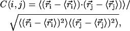
Key for the inchworm model of PcrA translocation are the alternating domain mobilities reflected in the potentials Uiσ(x) as shown in Fig. 2. To investigate this alternating asymmetry further we calculated the cross-correlation matrix of the PcrA-DNA complex. The matrix element is defined through
 |
(23) |
where  is the position of atom i (Cα in protein and P in DNA) obtained from an MD simulation and where 〈⋯〉 denotes the time average over the MD simulation. The correlation maps (colored according to the amplitude of C(i, j)) for substrate (s) and product (p) states are shown in Fig. 8 a. One can recognize that in state s the motion inside domain 1A is more strongly correlated than that inside domain 2A, while the opposite is true in state p. This character suggests that domain 1A is more rigid and less mobile than 2A in state s and becomes less rigid and more mobile than 2A in state p.
FIGURE 8.

Correlation analysis based on MD simulations (a) and a so-called dynamical coupling analysis based on an elastic network model (61) (b). The correlation maps in panel a are colored according to the amplitude of the cross correlation matrix element C(i, j) defined in the text. The matrices were calculated from 3-ns MD simulations for both the s and p states. In the s state, the average amplitude of cross correlation is ∼0.71 inside domain 1A and ∼0.68 inside domain 2A; in the p state, the average amplitude of cross correlation is ∼0.58 inside domain 1A and ∼0.63 inside domain 2A. The PcrA-DNA complexes in panel b are colored according to the dynamical coupling of residues to the fluctuations of the ATP binding pocket in both the s and p states. The dynamic coupling is probed (see (61)) through perturbation of a residue's spring constant and monitoring the ensuing effect on the vibrational fluctuation 〈δr2〉 of the ATP binding site. The protein, DNA, and ATP are shown in surface, licorice, and vdW presentations, respectively.
We also investigated the PcrA-DNA complex based on an elastic network model employing the method suggested in Zheng and Brooks (61) and provided as a web service (Web Server, AD-ENM. http://enm.lobos.nih.gov/). Following Zheng and Brooks (61), we calculated the residue contribution to the fluctuation of the ATP binding pocket in both the s and p states. The binding pocket includes altogether 80 residues on the seven conserved motifs (5,9), located between domains 1A and 2A; the residue contribution describes how the elastic motions of all residues are coupled to these 80 residues (for details, see (61)). One can see in Fig. 8 b that in the s state ssDNA nucleotides 15–17 are more strongly coupled, while in the p state ssDNA nucleotides 17–19 are more strongly coupled. We note here that nucleotides 15–17 are directly involved in the forward movement of domain 2A initiated from the s state, while nucleotides 17–19 are directly involved in the forward movement of domain 1A initiated from the p state (see above). The alternating coupling strength between ssDNA segments and ATP binding pocket also suggests alternating affinities between ssDNA segments and PcrA domains. Besides, it is interesting to notice that the analysis also identifies an important region, the loop containing Lys-385, contributing prominently to the fluctuation of ATP binding pocket, as shown in Fig. 8 b.
These results corroborate further the picture that binding of ATP to a PcrA-DNA complex alters essential global dynamic properties of domains 1A and 2A and of the ssDNA segments. The calculations reveal a certain dilemma of the present investigation: one sees from the stochastic model that alternating mobilities along with relative domain motions can explain PcrA translocation; yet, the mobilities are actually difficult to identify on the nanosecond timescale of MD simulations. But the combined evidence from nucleotide binding energies, steered molecular dynamics (SMD), cross correlation, and dynamic coupling analyses all point to a clear alternation of domain-ssDNA behavior that appears to be fundamental for PcrA translocation.
CONCLUSION
Combining nanosecond MD simulation and millisecond stochastic modeling, we studied monomeric PcrA helicase translocating along ssDNA. Based on structural information on the PcrA-DNA complex and equilibrium interaction energetics sampled from MD simulation, we derived the potential governing the movement of PcrA domains and simulated the stochastic dynamics of the translocation in two limiting scenarios. The advantage of utilizing MD simulation here is that we can estimate more realistically the potential and at the same time, trace the energy contribution to individual amino acids/nucleotides.
According to the derived potentials, the two translocating domains, 1A and 2A, in turn experience lower and higher energy barriers during the ATP hydrolysis cycle, so that the domains alternatively move along ssDNA, each in the same direction. Two limiting scenarios are proposed for PcrA translocation. In the weak coupling scenario, there is no interaction potential between domains; the domain experiencing the lower energy barriers in one state will move forward purely through random thermal motion; once the domain movement happens, some physical event, e.g., ATP binding, hydrolysis, or ADP+Pi dissociation, is stabilized or triggered. This in turn causes the conformation of the protein to be converted to that of the other state, in which only the other domain can move forward; in this scenario, the domain movements are rate-limiting.
In the strong coupling scenario, the two domains are facing relatively high barriers so that without interaction potential, neither can move; the interaction potential is driven by physical events such as ATP binding or ADP + Pi dissociation, which reduces the barriers so that the domain experiencing the lower reduced barrier quickly moves forward; the rate-limiting step in this scenario is any transition not involving domain movements.
Although it is not clear which scenario PcrA employs in reality, evidence suggests that PcrA works in a mixed scenario, in which ATP binding serves as a powerstroke facilitating the forward movement of domain 1A (and assists PcrA conformational change so that 1A cannot move backward), while ATP hydrolysis or ADP +Pi dissociation triggers the thermally agitated forward movement of domain 2A (and also assists PcrA conformational change to prevent 2A from moving backward). This scenario is shown schematically in Fig. 9.
FIGURE 9.

Five-step PcrA translocation cycle. The figure shows schematically a translocation cycle for a mixed scenario (weak coupling as well as strong coupling; see text) involving configurations 1–5 as well as configuration 1′, which is equivalent to configuration 1, except moved forward by one nt. The mixed scenario involves both a loaded spring (nonzero potential Vσ′(x1, x2), transition 2→3) and a step with a random thermal motion (vanishing potential Vσ′(x1, x2), transition 4→5). In configurations 1, 2, and 1′, domain 1A (green) moves more readily than domain 2A (red), while it is the opposite for configurations 3–5. The inset figures show how the domain and ssDNA base motions are coupled to the chemistry at the ATP binding site: upon the approach of domains 2A and 1A, Arg-287, and Arg-610 move close to the γ-phosphate of ATP; Gln-254 is linked closely to Tyr-257, which forms a key binding pocket for an ssDNA base, but squeezes out the base when the domains approach each other in binding ATP; Gln-254 has been identified as a key participant in ATP hydrolysis along with the mentioned arginines (17). The suggested mechanism therefore involves three steps: 1), binding of ATP that pulls domain 1A toward domain 2A; 2), insertion of Arg-287 and Arg-610 into an optimal (for hydrolysis) position in the ATP binding pocket along with Gln-254 linked to a key ssDNA interaction site; and 3), rapid hydrolysis of ATP that initiates separation of domains 2A and 1A through movement of 2A alone.
Fig. 9 depicts one PcrA translocation cycle involving five steps. In the first configuration, domains 2A and 1A are separated without ATP or ADP bound. The bases of the ssDNA track are shown in the insert to the left, revealing a base inserted between side groups Tyr-257 and Phe-64. Domain 1A can move more easily along ssDNA than can domain 2A. At this point ATP arrives at the binding site and begins to insert itself. The binding of ATP exerts an attractive force between the domains that consequently approach each other, but through motion of domain 1A, rather than 2A, leading to configuration 3. The close approach of domains 1A and 2A pushes Tyr-257 and Phe-64 together and, thereby, squeezes the ssDNA base out, it moving from its former position to a new position as indicated by the arrows in the inserted figures. The close approach of 2A and 1A brings Arg-610 and Arg-287 into close contact with the γ phosphate of ATP; the movement of Tyr-257 is transmitted to Gln-254. QM/MM calculations have shown that the three mentioned side groups, Arg-610, Arg-287, and Gln-254, control the hydrolysis of ATP in PcrA (17). In configuration 3 the juxtaposition of the three side groups presumably is optimal for hydrolysis of ATP to ADP + Pi, PcrA quickly reaching configuration 4. At this point the mobility of domains 2A and 1A has reversed, 2A being the one to move more easily. Thermal fluctuations leads 2A to separate then from 1A reaching configuration 5, permitting release of ADP and Pi, reaching configuration 1′. PcrA has advanced by one step and is ready, after binding another molecule of ATP, to continue its unidirectional movement.
In any scenario, the unidirectional translocation of PcrA is controlled by the barrier difference between two competing domain motions and alternating high and low barriers of the domain during a translocation cycle. Through this mechanism we identify key amino acids that play important roles sustaining PcrA translocation. The study may facilitate understanding not only of PcrA and other helicases, but also of other ATPases and molecular motors.
SUPPLEMENTARY MATERIAL
An online supplement to this article can be found by visiting BJ Online at http://www.biophysj.org.
Acknowledgments
The authors thank M. Dittrich for fruitful discussions and for sharing data from a QM/MM study of PcrA (17). Molecular images in this article were generated with the molecular graphics program VMD (64).
The present work was supported by National Institutes of Health grants No. P41-RR05969 and No. GM065367. The authors also acknowledge computer time provided through grant No. LRAC MCA93S028.
APPENDIX A: CONSTRUCTION OF CONTINUOUS SITE ENERGY FUNCTION
Having determined the relative binding free energies at individual nucleotide binding sites from MD simulations, we constructed a continuous site-energy function Eb(x) for each (s and p) state as shown schematically in Fig. 2, a and b, for the purpose of deriving the potentials Uiσ(x). The value Eb(x) represents the (relative) binding energy experienced by a nucleotide at position x. The actual curve Eb(x) is constructed by connecting the (five/six in s/p) binding free-energy values measured above through third-order polynomial interpolation, subject to the constraints (E′ = dE/dx; E″ = d2E/dx2):
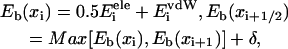 |
(24) |
 |
(25) |
 |
(26) |
The expressions xi, i = 15/14 (in s/p), …, 21, as defined in Fig. 2, are discrete positions of individual ssDNA units (for the nucleotides, numbered for convenience, see Fig. 1). The expressions x15/x14 (in s/p) and x21 correspond to boundary sites exposed to solvent. The site energy values, Eb(xi), of individual binding sites at locations xi are given in Eq. 24; the energy values, Eb(xi+1/2), at locations xi+1/2 between binding sites xi and xi+1 are also given in Eq. 24; the expression contains the term Max[Eb(xi), Eb(xi+1)] in order to mold an energy barrier into the function Uiσ(x) for a proper choice of δ as discussed in the main text. Here, δ is a single (the same for all xi) tunable parameter that controls the size of undulation of the site energy curve Eb(x). The first and second derivatives of Eb(x) at each site are given in Eq. 25. Periodic boundary conditions are enforced through Eq. 26, requiring both left and right boundary sites to have the same site energy; the value of this energy is discussed in the main text.
APPENDIX B: RATE CONSTANTS FOR DOMAIN MOTIONS
In Table 1 of the main text, we list the values of the rate constants for forward and backward barrier-crossing movements of domains 1A and 2A. Here we explain how these rate constants are evaluated. Each rate constant is evaluated as 1/τ, where τ is calculated as the mean first-passage time (9,27,63):
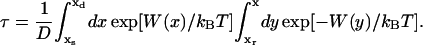 |
(27) |
Here, D is the diffusion coefficient D = kBT/γ (see Eq. 5 in Methods) assumed to be independent of x; xr is defined as a reflection boundary position, xs is the starting position of the domain motion, and xd is the destination position (values of xr, xs, and xd are listed in Table 2). We utilize the potential Wσσ′(x1, x2) (see Eq. 3 in Methods) in a specified state for only one domain to evaluate the corresponding rate constant, since the other domain remains stuck due to a high energy barrier. The explicit forms of W(x) ≡ Wσσ′(x, xfixed) in calculating τ by Eq. 27 are presented below in both the weak coupling and the strong coupling scenarios. For convenience of calculation, we use a simple sinusoidal function with amplitude Aiσ to represent the Uiσ(xi) term included in Wσσ′(x1, x2), since it is mainly the amplitude of the potential barrier that determines the value of τ in Eq. 27.
TABLE 2.
Position parameters in calculating the first-passage time, according to Eq. 27, for the corresponding domain motion
| Rate constants | Domain moving | Domain stuck | xr | xs | xd |
|---|---|---|---|---|---|
| r1 | 1A forward (x1) | 2A (x2 = 0) | l0 | l0 | l0/3 |
| s2 | 2A backward (x2) | 1A (x1 = l0) | 0 | 0 | 2l0/3 |
| r2 | 2A forward (x2) | 1A (x1 = 0) | 0 | −l0/3 | −l0 |
| s1 | 1A backward (x1) | 2A (x2 = 0) | 0 | l0/3 | l0 |
Note that the forward direction is along −x.
Weak coupling scenario
To evaluate r1 and s2 (see tier I in Fig. 6 a), which correspond to domain 1A moving forward and domain 2A moving backward, respectively, the following potentials are assumed:
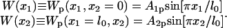 |
(28) |
To evaluate r2 and s1 (see tier II in Fig. 6 a), which correspond to 2A moving forward and 1A moving backward, respectively, the following potentials are assumed:
 |
(29) |
Strong coupling scenario
To evaluate r1 and s2 (see tier I in Fig. 6 b), which correspond to domain 1A moving forward and domain 2A moving backward, respectively, the following potentials are assumed (with parameter ls = l0/3):
 |
(30) |
To evaluate r2 and s1 (see tier II in Fig. 6 b), which correspond to 2A moving forward and 1A moving backward, respectively, the following potentials are assumed (with parameter lp = l0):
 |
(31) |
APPENDIX C: EXPLICIT EXPRESSION OF VELOCITY
In Eq. 22 of the main text, we give the expression of the velocity v for PcrA translocation along ssDNA, which is derived from a calculation of stationary probability fluxes. The value v is calculated to be −(r1r2 − s1s2)C, as given in Eq. 22; the explicit expression of C, in terms of rate constants r1, r2, s1, s2 and ωI, ωII, is given below, for both the weak coupling and the strong coupling scenarios.
In case of the weak coupling scenario, ωI = ωII = ω holds
 |
(32) |
In case of the strong coupling scenario and ωI = ω′I = ω′II = ω, with chemical potential μ and energy difference ΔE (see Fig. 6 b), holds
 |
(33) |
where
 |
(34) |
References
- 1.Lohman, T., and K. Bjornson. 1996. Mechanisms of helicase-catalyzed DNA unwinding. Annu. Rev. Biochem. 65:169–214. [DOI] [PubMed] [Google Scholar]
- 2.Bird, L., S. Subramanya, and D. Wigley. 1998. Helicases: a unifying structural theme. Curr. Opin. Struct. Biol. 8:14–18. [DOI] [PubMed] [Google Scholar]
- 3.Waksman, G., E. Lanka, and J. Carazo. 2000. Helicases as nucleic acid unwinding machines. Nat. Struct. Biol. 7:20–22. [DOI] [PubMed] [Google Scholar]
- 4.Marians, K. 2001. Crawling and wiggling on DNA: structural insights to the mechanism of DNA unwinding by helicases. Structure. 8:R227–R235. [DOI] [PubMed] [Google Scholar]
- 5.Caruthers, J., and D. McKay. 2002. Helicase structure and mechanism. Curr. Opin. Struct. Biol. 12:123–133. [DOI] [PubMed] [Google Scholar]
- 6.van Brabant, A., R. Stan, and N. A. Ellis. 2000. DNA helicases, genomic instability, and human genetic disease. Annu. Rev. Genomics Hum. Genet. 1:409–459. [DOI] [PubMed] [Google Scholar]
- 7.von Hippel, P. 2004. Helicases become mechanistically simpler and functionally more complex. Nat. Struct. Biol. 11:494–496. [DOI] [PubMed] [Google Scholar]
- 8.Velankar, S., P. Soultanas, M. Dillingham, H. Subramanya, and D. Wigley. 1999. Crystal structures of complexes of PcrA DNA helicase with a DNA substrate indicate an inchworm mechanism. Cell. 97:75–84. [DOI] [PubMed] [Google Scholar]
- 9.Hall, M., and S. Matson. 1999. Helicase motifs: the engine that powers DNA unwinding. Mol. Microbiol. 34:867–877. [DOI] [PubMed] [Google Scholar]
- 10.Cheng, W., J. Hsieh, K. Brendza, and T. Lohman. 2001. E. coli Rep oligomers are required to initiate DNA unwinding in vitro. J. Mol. Biol. 310:327–350. [DOI] [PubMed] [Google Scholar]
- 11.Ha, T., I. Rasnik, W. Cheng, H. Babcock, G. Gauss, T. Lohman, and S. Chu. 2002. Initiation and re-initiation of DNA unwinding by the Escherichia coli Rep helicase. Nature. 419:638–641. [DOI] [PubMed] [Google Scholar]
- 12.Maluf, N., C. Fischer, and T. Lohman. 2003. A dimer of E. coli UvrD is the active form of the helicase in vitro. J. Mol. Biol. 325:913–935. [DOI] [PubMed] [Google Scholar]
- 13.Dillingham, M., D. Wigley, and M. Webb. 2000. Demonstration of unidirectional single-stranded DNA translocation by PcrA helicase: measurement of step size and translocation speed. Biochemistry. 39:205–212. [DOI] [PubMed] [Google Scholar]
- 14.Brendza, K., W. Cheng, C. Fischer, M. Chesnik, A. Niedziela-Majka, and T. Lohman. 2005. Autoinhibition of Escherichia coli Rep monomer helicase activity by its 2B subdomain. Proc. Natl. Acad. Sci. USA. 102:10076–10081. [DOI] [PMC free article] [PubMed] [Google Scholar]
- 15.Myong, S., I. Rasnik, C. Joo, T. Lohman, and T. Ha. 2005. Repetitive shuttling of a motor protein on DNA. Nature. 322:1321–1325. [DOI] [PubMed] [Google Scholar]
- 16.Fischer, C., N. Maluf, and T. Lohman. 2004. Mechanism of ATP-dependent translocation of E. coli UvrD monomers along single-stranded DNA. J. Mol. Biol. 344:1287–1309. [DOI] [PubMed] [Google Scholar]
- 17.Dittrich, M., and K. Schulten. 2006. PcrA helicase, a prototype ATP driven molecular motor. Structure. In press. [DOI] [PubMed]
- 18.Chennubhotla, C., A. Rader, L.-W. Yang, and I. Bahar. 2005. Elastic network models for understanding biomolecular machinery: from enzymes to supramolecular assemblies. Phys. Biol. 2:S173–S180. [DOI] [PubMed] [Google Scholar]
- 19.Aksimentiev, A., I. Balabin, R. Fillingame, and K. Schulten. 2004. Insights into the molecular mechanism of rotation in the Fo sector of ATP synthase. Biophys. J. 86:1332–1344. [DOI] [PMC free article] [PubMed] [Google Scholar]
- 20.Ma, J., T. C. Flynn, Q. Cui, A. G. W. Leslie, J. E. Walker, and M. Karplus. 2002. A dynamics analysis of the rotation mechanism for conformational change in F1-ATPase. Structure. 10:921–931. [DOI] [PubMed] [Google Scholar]
- 21.Wang, H., and G. Oster. 2002. Ratchets, power strokes, and molecular motors. Appl. Phys. A. 75:315–323. [Google Scholar]
- 22.Betterton, M., and F. Jülicher. 2003. A motor that makes its own track: helicase unwinding of DNA. Phys. Rev. Lett. 91:258103. [DOI] [PubMed] [Google Scholar]
- 23.Betterton, M., and F. Jülicher. 2005. Opening of double nucleic-acids strands by helicases: active versus passive opening. Phys. Rev. E. 71:011904. [DOI] [PubMed] [Google Scholar]
- 24.Betterton, M., and F. Jülicher. 2005. Velocity and processivity of helicase unwinding of double-stranded nucleic acids. J. Phys. Cond. Mater. 17:S3851–S3869. [DOI] [PubMed] [Google Scholar]
- 25.Wong, I., and T. Lohman. 1992. Allosteric effects of nucleotide cofactors on Escherichia coli Rep helicase-DNA binding. Science. 256:350–355. [DOI] [PubMed] [Google Scholar]
- 26.Yarraton, G. T., and M. L. Geftner. 1979. Enzyme-catalyzed DNA unwinding: studies on Escherichia coli rep protein. Proc. Natl. Acad. Sci. USA. 76:1658–1662. [DOI] [PMC free article] [PubMed] [Google Scholar]
- 27.Howard, J. 2001. Mechanics of Motor Proteins and the Cytoskeleton. Sinauer Associates, Sunderland, MA.
- 28.Fall, C. P., E. S. Marland, J. M. Wagner, and J. Tyson, editors. 2002. Computational Cell Biology. Springer-Verlag, New York.
- 29.Gardiner, C. 2002. Handbooks of Stochastic Methods. Springer-Verlag, Berlin, Heidelberg, New York.
- 30.Kubo, R. 1966. The fluctuation-dissipation theorem. Rep. Prog. Phys. 29:255–284. [Google Scholar]
- 31.Landau, D., and K. Binder. 2000. A Guide to Monte Carlo Simulations in Statistical Physics. Cambridge University Press, New York.
- 32.Fichthorn, K. A., and W. H. Weinberg. 1991. Theoretical foundations of dynamical Monte Carlo simulations. J. Chem. Phys. 95:1090–1096. [Google Scholar]
- 33.Gillespie, D. T. 1976. A general method for numerically simulating the stochastic time evolution of coupled chemical reactions. J. Comput. Phys. 22:403–434. [Google Scholar]
- 34.Allen, R., P. Warren, and P. ten Wolde. 2005. Sampling rare switching events in biochemical networks. Phys. Rev. Lett. 94:018104. [DOI] [PubMed] [Google Scholar]
- 35.Park, S., K. S. Melih, D. Lu, and K. Schulten. 2003. Reaction paths based on mean first-passage times. J. Chem. Phys. 119:1313–1319. [Google Scholar]
- 36.Elber, R. 1996. Recent Developments in Theoretical Studies of Proteins. R. Elber, editor. World Scientific, Singapore.
- 37.Straub, J. E. 2001. Computational Biochemistry and Biophysics. O. Becker, A. MacKerell, J. Roux, and M. Watanabe, editors. Marcel Dekker, New York.
- 38.Åqvist, J., C. Medina, and J. Samuelsson. 1994. A new method for predicting binding affinity in computer-aided drug design. Protein Eng. 7:385–391. [DOI] [PubMed] [Google Scholar]
- 39.Åqvist, J. 1996. Calculation of absolute binding free energies for charged ligands and effects of long-range electrostatic interaction. J. Comput. Chem. 17:1587–1597. [Google Scholar]
- 40.Wang, W., J. Wang, and P. A. Kollman. 1999. What determines the van der Waals coefficient in the lie (linear interaction energy) method to estimate binding free energies in molecular dynamics simulations. Proteins. 34:395–402. [PubMed] [Google Scholar]
- 41.Torrie, G., and J. Valleau. 1974. Monte Carlo free energy estimates using non-Boltzmann sampling: application to the sub-critical Lennard-Jones fluid. Chem. Phys. Lett. 28:578–581. [Google Scholar]
- 42.Isralewitz, B., M. Gao, and K. Schulten. 2001. Steered molecular dynamics and mechanical functions of proteins. Curr. Opin. Struct. Biol. 11:224–230. [DOI] [PubMed] [Google Scholar]
- 43.Jarzynski, C. 1997. Nonequilibrium equality for free energy differences. Phys. Rev. Lett. 78:2690–2693. [Google Scholar]
- 44.Park, S., and K. Schulten. 2004. Calculating potentials of mean force from steered molecular dynamics simulations. J. Chem. Phys. 120:5946–5961. [DOI] [PubMed] [Google Scholar]
- 45.Korolev, S., J. Hsieh, G. H. Gauss, T. M. Lohman, and G. Waksman. 1997. Major domain swiveling revealed by the crystal structure of complexes of E. coli Rep helicase bound the single-stranded DNA and ADP. Cell. 90:635–647. [DOI] [PubMed] [Google Scholar]
- 46.Rocchia, W., S. Sridharan, A. Nicholls, E. Alexov, A. Chiabrera, and B. Honig. 2002. Rapid grid-based construction of the molecular surface and the use of induced surface charge to calculate reaction field energies: applications to the molecular systems and geometric objects. J. Comput. Chem. 23:128–137. [DOI] [PubMed] [Google Scholar]
- 47.Phillips, J., R. Braun, W. Wang, J. Gumbart, E. Tajkhorshid, E. Villa, C. Chipote, R. Skeel, L. Kale, and K. Schulten. 2005. Scalable molecular dynamics with NAMD. J. Comput. Chem. 26:1781–1802. [DOI] [PMC free article] [PubMed] [Google Scholar]
- 48.MacKerell, A. D., Jr., C. L. Brooks III, L. Nilsson, B. Roux, Y. Won, and M. Karplus. 1998. CHARMM: the energy function and its parameterization with an overview of the program. In The Encyclopedia of Computational Chemistry, Vol. 1. P. Schleyer et al., editors. John Wiley and Sons, Chichester.
- 49.Batcho, P. F., D. A. Case, and T. Schlick. 2001. Optimized particle-mesh Ewald/multiple-time step integration for molecular dynamics simulations. J. Chem. Phys. 115:4003–4018. [Google Scholar]
- 50.Martyna, G. J., D. J. Tobias, and M. L. Klein. 1992. Constant pressure molecular dynamics algorithms. J. Chem. Phys. 2:4177–4189. [Google Scholar]
- 51.Feller, S. E., Y. Zhang, R. W. Pastor, and B. R. Brooks. 1995. Constant pressure molecular dynamics simulation—the Langevin piston method. J. Chem. Phys. 103:4613–4621. [Google Scholar]
- 52.Brunger, A. T. 1992. X-PLOR, Version 3.1: A System for X-Ray Crystallography and NMR. The Howard Hughes Medical Institute and Department of Molecular Biophysics and Biochemistry, Yale University.
- 53.Izrailev, S., S. Stepaniants, M. Balsera, Y. Oono, and K. Schulten. 1997. Molecular dynamics study of unbinding of the avidin-biotin complex. Biophys. J. 72:1568–1581. [DOI] [PMC free article] [PubMed] [Google Scholar]
- 54.Sotomayor, M., D. P. Corey, and K. Schulten. 2005. In search of the hair-cell gating spring: elastic properties of ankyrin and cadherin repeats. Structure. 13:669–682. [DOI] [PubMed] [Google Scholar]
- 55.Dittrich, M., S. Hayashi, and K. Schulten. 2003. On the mechanism of ATP hydrolysis in F1-ATPase. Biophys. J. 85:2253–2266. [DOI] [PMC free article] [PubMed] [Google Scholar]
- 56.Wolfram Research, Inc. 2005. Mathematica Ver. 5.2. Wolfram Research, Champaign, IL.
- 57.Nishizaka, T., K. Oiwa, H. Noji, S. Kimura, E. Muneyuki, M. Yoshida, and K. Kinosita, Jr. 2004. Chemomechanical coupling in F1-ATPase revealed by simultaneous observation of nucleotide kinetics and rotation. Nat. Struct. Biol. 11:142–148. [DOI] [PubMed] [Google Scholar]
- 58.Shimabukuro, K., R. Yasuda, E. Muneyuki, K. Y. Hara, K. J. Kinosita, and M. Yoshida. 2003. Catalysis and rotation of F1 motor: cleavage of ATP at the catalytic site occurs in 1 ms before 40° substep rotation. Proc. Natl. Acad. Sci. USA. 100:14731–14736. [DOI] [PMC free article] [PubMed] [Google Scholar]
- 59.Reference deleted in proof.
- 60.Dillingham, M., P. Soultanas, and D. Wigley. 1999. Site-directed mutagenesis of motif II in PcrA helicase reveals a role in coupling ATP hydrolysis to strand separation. Nucleic Acids Res. 27:3310–3317. [DOI] [PMC free article] [PubMed] [Google Scholar]
- 61.Zheng, W., and B. Brooks. 2005. Identification of dynamical correlations within the myosin motor domain by the normal mode analysis of an elastic network model. J. Mol. Biol. 346:745–759. [DOI] [PubMed] [Google Scholar]
- 62.Reference deleted in proof.
- 63.Szabo, A., K. Schulten, and Z. Schulten. 1980. First passage time approach to diffusion controlled reactions. J. Chem. Phys. 72:4350–4357. [Google Scholar]
- 64.Humphrey, W., A. Dalke, and K. Schulten. 1996. VMD visual molecular dynamics. J. Mol. Graph. 14:33–38. [DOI] [PubMed] [Google Scholar]