Abstract
We report an approach for the detection of magnetic resonance imaging without superconducting magnets and cryogenics: optical atomic magnetometry. This technique possesses a high sensitivity independent of the strength of the static magnetic field, extending the applicability of magnetic resonance imaging to low magnetic fields and eliminating imaging artifacts associated with high fields. By coupling with a remote-detection scheme, thereby improving the filling factor of the sample, we obtained time-resolved flow images of water with a temporal resolution of 0.1 s and spatial resolutions of 1.6 mm perpendicular to the flow and 4.5 mm along the flow. Potentially inexpensive, compact, and mobile, our technique provides a viable alternative for MRI detection with substantially enhanced sensitivity and time resolution for various situations where traditional MRI is not optimal.
Keywords: low field, remote detection
Magnetic resonance imaging (MRI) is used in fields as diverse as medicine, material science, and geology to noninvasively extract unique information from samples ranging from human tissues to solid silicone rubber to porous rocks (1, 2). Traditional MRI is limited, however, by the use of high magnetic fields. MRI generally uses Faraday induction (which at a given initial level of polarization yields a signal with magnitude proportional to the static magnetic field) to detect the changes in magnetic flux generated by the Larmor precession of the nuclear spins in the sample (3). A superconducting magnet is typically used to provide a strong magnetic field and increase signal; the resulting cost and constrained accessibility limit the applicability of MRI. Furthermore, high fields are not favorable for certain measurements, including those involving heterogeneous samples with large magnetic-susceptibility gradients. Low-field MRI would eliminate the costs and constraints of the superconducting magnet and allow experiments that are currently inhibited by high-field susceptibility issues. Measurements in low fields are typically problematic, however, because traditional Faraday detection suffers from low sensitivity at fields much less than a Tesla.
For improved sensitivity at low fields, superconducting quantum interference devices (4–6) have been used in MRI (7, 8). Unfortunately, these devices require cryogenics, which add significant cost and exclude applications where cryogenics are not readily available, such as in open fields and space. The sensitivity to a dc magnetic field is also rather poor. Furthermore, because of fairly complicated electronics, implementation of multiple-channel detection to enhance detection sensitivity and efficiency is not convenient. A different technique is needed to overcome these limitations. Recent developments in optical atomic magnetometry (9–11), which is based on magneto-optical rotation in a “sensor” atomic vapor, have made it a viable alternative for detecting weak magnetic fields, eliminating the need for cryogenics and complicated electronics (12). Applications of atomic magnetometers have been demonstrated only with simple free induction decay of nuclear magnetization (13, 14). We here report MRI by optical atomic magnetometry.
Another major factor affecting detection sensitivity is the filling factor of the sample. When the nuclear spins are spread out over a large volume, detection becomes less sensitive. For fluidic analytes, the spins can be concentrated in a detection region and the problem can be circumvented by remote detection (15–17): a sample is first prepolarized; then it enters an encoding region where large radio frequency coils that cover the whole sample area store spectroscopic or spatial information as nuclear magnetization along the longitudinal axis; downstream the sample is concentrated and its magnetization is measured with improved filling factor.
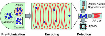
By adopting a remote-detection scheme, the sensitive detectors become immune to the encoding magnetic fields and allow measurements to be performed continuously. The possible coupling of various detection methods with remote detection is schematically illustrated in Fig. 1.
Fig. 1.
Various prepolarization and detection methods for MRI in combination with remote detection. To overcome the limited nuclear polarization in low magnetic fields, prepolarization methods can be applied, including spin-exchange optical pumping by lasers, polarization by cryogenics, and thermal polarization by permanent magnets. In the encoding stage, excitation pulses and gradient pulses are applied to store spatial information as nuclear spin magnetization. For detection, the methods of optical atomic magnetometer, radio frequency (RF) coil, and superconducting quantum interference device (SQUID) are shown.
In this article, we demonstrate the application of optical atomic magnetometry to low-field MRI, with time-resolved images of water flow obtained by using remote detection.
Results and Discussion
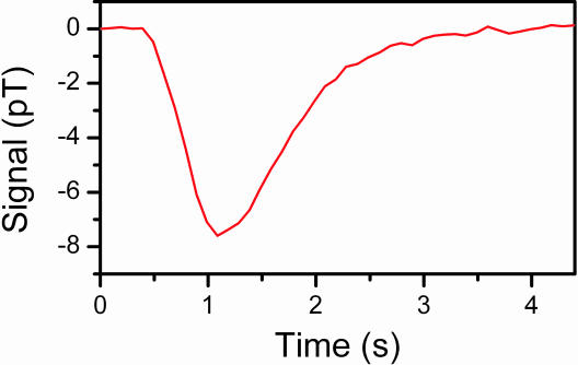
A typical flow profile (average of 30 measurements) is shown in Fig. 2. After the encoding π pulse, the signal (the absolute magnetization difference) reaches its maximum at 1.1 s, with a time dispersion of 1.0 s (full-width half-maximum). The dispersion results from time variation in the transfer of water from the encoding channels to the thinner transport tube.
Fig. 2.
Flow profile of water measured by magnetization inversion by a single π pulse.
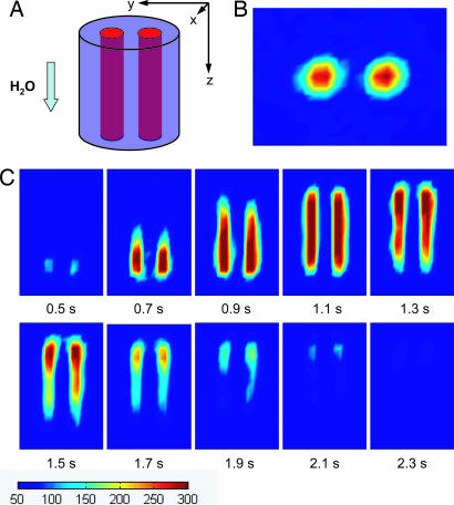
Magnetic resonance images obtained by phase encoding are demonstrated in Fig. 3. Fig. 3A shows a schematic of the encoding volume, which is composed of two parallel cylindrical channels. Fig. 3B shows the image of the cross-section (the xy plane) of the encoding volume perpendicular to the flow direction. For imaging in the plane of the flow direction, gradients Gy and Gz are applied. The resulting images are shown in Fig. 3C. The lower parts (outlet side of the encoding volume) of the images represent those portions of the sample closer to the magnetometer and therefore arriving at the detection region earlier, starting at 0.5 s. In the frame at 1.1 s, the intensity distribution shows that the detection volume is filled with the encoded water, consistent with the maximum difference signal in the flow profile of Fig. 2. Then water flows out of the detection region, with the upper parts (inlet side of the encoding volume) lasting until 2.3 s. Therefore the images demonstrate the flow behavior, temporally and spatially resolved, of the encoded water. The temporal resolution is 0.1 s. The spatial resolution of the images is 1.6 mm cross the flow and 4.7 mm along the flow direction, each being 1/5 of the overall length along the respective axis, corresponding to a detection limit of 10 μl.
Fig. 3.
Magnetic resonance images. (A) The encoding volume. The two channels are 3.2 mm in diameter and 25 mm long each, with a center-to-center spacing of 5.1 mm. (B) Image of the cross-section of the encoding volume perpendicular to the flow (xy plane) at t = 1.1 s. (C) Time-resolved images in the yz plane. Measurements were obtained with a time interval of 0.1 s. All of the images are color-mapped at the same scale, as indicated below the images. The total experimental time for these flow images is 12 h, which is dominated by the waiting time between measurements to allow the sample from the previous measurement cycle to clear the system. The overall time will be reduced to minutes with shorter travel distances.
The imaging resolution can be further improved. Currently, it is affected by the long time delay between samples leaving the prepolarization and arriving at the detection region, as the polarization of water relaxes exponentially during this period. The total time delay in the present experiments, 2.5 s, can be shortened to ≈0.1 s by reducing the travel volume, resulting in a detection limit of ≈1 μl of thermally polarized water, with a temporal resolution ≈0.1 s. In addition, the prepolarization field can be increased to 1 T with permanent magnets, bringing the detection limit into the nanoliter regime, corresponding to micrometer resolution in all three dimensions. With further optimization and improvement to the magnetometer, such as adding more detection channels decreasing distance between the rubidium cells and the sample for a better detection filling factor, we expect to gain another order of magnitude in sensitivity.
Our technique has several advantages over conventional MRI. It directly measures the magnetic field generated by the sample, as opposed to the conventional measurement in the transverse plane; because no radio frequency pulses are applied to the encoded sample for detection, signals can be continuously monitored. The time-resolved images illustrate this as we observe the complete filling and emptying process of the detection volume. Low-field detection also opens up avenues of investigations of samples that contain high magnetic-susceptibility gradients, such as the study of porous material with paramagnetic impurities and medical imaging in the presence of metal implants. This technique is also useful for samples that are too big to be introduced into the bore of a superconducting magnet. Furthermore, atomic magnetometers require no cryogenics, making MRI applicable for situations where no cryogenics are available, while dramatically reducing cost, size, and maintenance of the apparatus. Finally, the system can be designed to use an economical miniature vertical-cavity-surface-emitting laser, and the electronics and optics can be consolidated for multiple channel detection. We anticipate that the whole apparatus will become quite compact and deployable as a battery-powered portable device.
A small, highly sensitive MRI scanner will be suitable for remote microfluidic MRI recently developed in our laboratory by using high-field detection (18), making it possible to characterize noninvasively the flow and reactions in microchannels in low magnetic fields. The apparatus can be used as an in-line analytic tool where a large high-field instrument is impractical to perform measurements without disturbing ongoing chemical or biochemical reactions. Our results also show that the spatial information encoded as longitudinal magnetization is preserved during the course of travel and subsequently resolvable by detection of the magnetization in the detection region. This spatial resolution will be useful in low magnetic fields where chemical shifts are not resolvable: chemically different samples located in separate microchannels can be encoded spatially and still give chemical-specific information based solely on physical location. Spatial encoding also allows for the study of flow dynamics of multiple components simultaneously, without the need for chemical differentiation.
In conclusion, we have presented results for low-field MRI using an optical atomic magnetometer. With its outstanding sensitivity in low fields, mobility, and low cost, this technique is ideal for many situations in which conventional MRI is not feasible.
Experimental Procedures
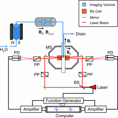
Our recently constructed apparatus, details of which will be provided elsewhere, measures time-dependent nonlinear magneto-optical rotation of the polarization of a frequency-modulated laser beam interacting with a rubidium vapor (Fig. 4). A resonance is generated when the modulation frequency equals twice the Larmor precession frequency gμB/h, where B is the magnetic field, g is the known atomic gyromagnetic ratio, μ is the Bohr magneton, and h is Planck’s constant. A bias magnetic field establishes a baseline resonance frequency and defines the detection axis of the magnetometer. When polarized nuclear spins are introduced, the change in the resonance frequency is proportional to the sample field along the detection axis. The atomic magnetometer uses two rubidium cells that form a gradiometer to cancel environmental common-mode noise. The near-dc (0.1 Hz) sensitivity of this magnetometer is 80 fT/Hz1/2.
Fig. 4.
Schematic of the experimental setup. The magnetometer consists of two rubidium (87Rb) vapor cells forming a first-order gradiometer. The cells are cubic, with a 1-cm side length, and maintained at 43°C. The beam from a single laser (whose wavelength is resonant with the rubidium D1 transition) is split equally into two, one for each cell. For each arm of the gradiometer, polarizing and analyzing prisms are oriented at 45° to each other to detect optical rotation occurring in the vapor cell. The intrinsic resonance linewidth is ≈5 Hz. A piercing solenoid provides a 0.05-mT leading field (Bl). The geometry is such that the rubidium atoms are not subject to this field. A bias field of 70 nT (Bb) gives a resonance frequency of ≈1,000 Hz for the modulation of the laser when no sample is introduced. The magnetometer measures the magnetic field change along the direction of the bias field. The magnetized sample in the detection region produces magnetic fields of opposite direction in the two cells. The frequency of magneto-optical resonance on one arm of the gradiometer is fed back to the laser modulation to maintain this arm on resonance. Thus the optical rotation in the other cell represents the difference field between the two cells, equal to twice the magnetic field produced by the sample. N, north pole; S, south pole; PD, photo diode; PP, polarization prism; MS, magnetic shield; BS, beam splitter.
During the experiments, a continuous stream of water, driven by high-pressure nitrogen (8 atm), first spends ≈15 s in a 0.3-T magnetic field for prepolarization. It then flows through two cylindrical channels in an encoding field of 3.1 mT (B0) (corresponding to a proton Larmor frequency of 132 kHz) directed parallel to the water flow. Finally, the water is delivered through a thin transport tube to the magnetometer where the magnetization is read out. The flow scheme of water is also demonstrated in Fig. 4. The polarization adiabatically follows the local magnetic field, which is the laboratory field between regions.
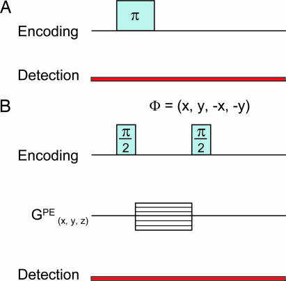
To obtain the flow profile, a π pulse was applied to invert the spins in the encoding volume, causing a change in magnetic field from the baseline magnetization produced by prepolarization (Fig. 5A).
Fig. 5.
Pulse sequences used in the experiments. (A) A π pulse used to invert the spins for measuring the flow profile. The pulse duration is 116 μs. The detection timing of the magnetometer is relative to the π pulse. (B) Phase-encoding pulse sequence for magnetic resonance imaging. The pulse duration is 58 μs for the π/2 pulses and 1.2 ms for the phase-encoding gradient pulses (GPE). The gradient step sizes were 0.3, 0.22, and 0.1 G/cm, for axes x, y, and z (flow direction), respectively. The number of steps are 10, 14, and 10 for x, y, and z, respectively.
Two-dimensional images of the water flow were obtained by using a phase-encoding pulse sequence (Fig. 5B): a π/2 pulse first rotates the magnetization into the plane perpendicular to the encoding magnetic field; the resulting transverse magnetization processes in the presence of the gradient magnetic fields; a second π/2 pulse stores one component of the phase-encoded magnetization along the longitudinal axis, which can then be remotely detected by the atomic magnetometer. Both the x and y components of the transverse magnetization are measured by performing a phase cycle on the second π/2 pulse. By incrementing the gradient amplitudes along respective spatial encoding axes, the corresponding image is obtained through Fourier transformation. The imaging sequences were repeated 16 times and averaged to create the image.
Acknowledgments
We thank Josef Granwehr, Christian Hilty, and Elad Harel for helpful discussions. This work was supported by the Director of the Office of Science (Materials Sciences Division of the U.S. Department of Energy). D.B. acknowledges support by an Office of Naval Research Multidisciplinary University Research Initiative grant.
Footnotes
Conflict of interest statement: No conflicts declared.
See Commentary on page 12657.
References
- 1.Callaghan P. T. Principles of Nuclear Magnetic Resonance Microscopy. New York: Clarendon; 1991. [Google Scholar]
- 2.Blümich B. NMR Imaging of Materials. Oxford: Oxford Univ. Press; 2000. [Google Scholar]
- 3.Hoult D. I., Richards R. E. J. Magn. Reson. 1976;24:71–85. doi: 10.1016/j.jmr.2011.09.018. [DOI] [PubMed] [Google Scholar]
- 4.Kleiner R., Koelle D., Ludwig F., Clarke J. Proc. IEEE; 2004. pp. 1534–1548. [Google Scholar]
- 5.Oukhanski N., Stolz R., Zakosarenko V., Meyer H. G. Physica C. 2002;368:166–170. [Google Scholar]
- 6.McDemont R., Trabesinger A. H., Mück M., Hahn E. L., Pines A., Clarke J. Science. 2002;295:2247–2249. doi: 10.1126/science.1069280. [DOI] [PubMed] [Google Scholar]
- 7.Wong-Foy A., Saxena S., Moulé A. J., Bitter H.-M. L., Seeley J. A., McDermott R., Clarke J., Pines A. J. Magn. Reson. 2002;157:235–241. doi: 10.1006/jmre.2002.2592. [DOI] [PubMed] [Google Scholar]
- 8.Lee S. K., Möβle M., Myers W., Kelso N., Trabesinger A. H., Pines A., Clarke J. Magn. Reson. Med. 2005;53:9–14. doi: 10.1002/mrm.20316. [DOI] [PubMed] [Google Scholar]
- 9.Cohen-Tannoudji C., DuPont-Roc J., Haroche S., Lahoë F. Phys. Rev. Lett. 1969;22:758–760. [Google Scholar]
- 10.Budker D., Gawlik W., Kimball D. F., Rochester S. M., Yashchuk V. V., Weis A. Rev. Mod. Phys. 2002;74:1153–1202. [Google Scholar]
- 11.Savukov I. M., Seltzer S. J., Romalis M. V., Sauer K. L. Phys. Rev. Lett. 2005;95:063004. doi: 10.1103/PhysRevLett.95.063004. [DOI] [PubMed] [Google Scholar]
- 12.Kominis I. K., Kornack T. W., Allred J. C., Romalis M. V. Nature. 2003;422:596–599. doi: 10.1038/nature01484. [DOI] [PubMed] [Google Scholar]
- 13.Yashchuk V. V., Granwehr J., Kimball D. F., Rochester S. M., Trabesinger A. H., Urban J. T., Budker D., Pines A. Phys. Rev. Lett. 2004;93:160801. doi: 10.1103/PhysRevLett.93.160801. [DOI] [PubMed] [Google Scholar]
- 14.Savukov I. M., Romalis M. V. Phys. Rev. Lett. 2005;94:123001. doi: 10.1103/PhysRevLett.94.123001. [DOI] [PubMed] [Google Scholar]
- 15.Moulé A. J., Spence M. M., Han S.-I., Seeley J. A., Pierce K. L., Saxena S., Pines A. Proc. Natl. Acad. Sci. USA. 2003;100:9122–9127. doi: 10.1073/pnas.1133497100. [DOI] [PMC free article] [PubMed] [Google Scholar]
- 16.Seeley J. A., Han S.-I., Pines A. J. Magn. Reson. 2004;167:282–290. doi: 10.1016/j.jmr.2003.12.018. [DOI] [PubMed] [Google Scholar]
- 17.Granwehr J., Harel E., Han S.-I., Garcia S., Pines A., Sen P. N., Song Y. Q. Phys. Rev. Lett. 2005;95:075503. doi: 10.1103/PhysRevLett.95.075503. [DOI] [PubMed] [Google Scholar]
- 18.Hilty C., McDonnell E. E., Granwehr J., Pierce K. L., Han S.-I., Pines A. Proc. Natl. Acad. Sci. USA. 2005;102:14960–14963. doi: 10.1073/pnas.0507566102. [DOI] [PMC free article] [PubMed] [Google Scholar]


