Abstract
This review presents findings made in studies of large mammalian bones, especially from racehorse training experiments (2–8 years old, third metacarpal, tarsal) and human autopsy orthopaedic femoral implant retrievals and other human biopsy and autopsy cases. Samples were cleaned to analyse mineralized matrix in three dimensions, or poly methyl-methacrylate embedded and micromilled to delete topography and study the superficial c. 0.5-µm two-dimensional section using quantitative backscattered electron imaging. With experimental implant studies in rabbits, observations were also made in vivo using confocal microscopy. Cracks in both calcified cartilage and bone may be removed by infilling with calcified matrix. This may be a general repair mechanism for calcified connective tissue crack repair. The fraction of the organ volume occupied by any form of bone tissue in equine distal third metacarpal extremities was increased in the more exercised groups by bone deposited within former marrow adipocytic space. Where deposited upon prior lamellar bone surfaces, this occurred without the intervention of prior resorption and without the formation of a hypermineralized cement line. Exercise inhibited osteoclastic resorption at external anatomical growth modelling sites where it normally occurs. Addition is not coupled to time-wasting resorption: both internally and externally, it occurs both by layering on existing cancellous surfaces and by creation of new immature scaffold, with de novo incorporation of a rich, capillary blood vessel supply. The real response within bone organs subjected to mechanical overload exercise within normal physiological limits is to make more, and to lose less, bone.
Keywords: bone, crack sealing, microfracture, osteoporosis, scanning electron microscopy
Introduction
Microdamage accumulation is widely accepted as a general phenomenon in bone and many authors assume that it, or associated osteocytic death, in some way signals a need for replacement of volumes of possibly effete bone tissue within bone organs (Burr & Stafford, 1990; Schaffler et al. 1994; Burr & Hooser, 1995; Mori et al. 1997; Noble et al. 1997, 2003; Tomkinson et al. 1997; Bentolila et al. 1998; Burr et al. 1998; Fazzalari et al. 1998a,b; Frost, 1998; Lee et al. 1998; Norrdin et al. 1998; Huja et al. 1999; Reilly & Currey, 1999; Noble & Reeve, 2000; O’Brien et al. 2000; Vashishth et al. 2000a,b; Frisch et al. 2001; You et al. 2001; Zioupos, 2001; Tami et al. 2002; Verborgt et al. 2002; Yeni et al. 2002). Evidence adduced for the existence of microdamage in vivo is sometimes questionable. There is little evidence to support an association of events – other than that older, and therefore the more likely to be cracked, bone may be eventually replaced during turnover.
Bone repair and replacement is widely assumed to be site-coupled to prior osteoclastic resorption. However, the generally used means and material for examining this relationship, particularly in older human material, are inefficient and inadequate.
I review evidence here that some cracks in bone (and bone substitute materials) may anneal and heal in situ without the removal of the damaged domain; that osteocytes withstand serious offence through iatrogenic microcracking; that osteocytes that do die, do calcify; and that much new bone that forms in response to serious exercise-induced loading forms remote from osteoblast-covered bone surfaces and without any intervening osteoclastic resorptive event.
Materials and methods
The materials used in this study are listed in Table 1.
Table 1.
List of species/sites considered/multidimensional imaging of bone in studying crack propagation in vivo and in vitro, and/or new bone formation in response to exercise or overload
| Thoroughbred racehorse treadmill and training experiments (18 months old, third metacarpal) (courtesy of A. E. Goodship, Bristol, UK; Boyde et al. 1997) |
| Thoroughbred racehorse grass track training experiments (2 years old, third metacarpal) (courtesy of E. C. Firth, Massey University Grass Exercise Study, Palmerston North, New Zealand; Boyde et al. 2001) |
| Thoroughbred racehorse, tarsal bones, 0–8 years old with known exercise histories (courtesy of A. P. Bathe, Cambridge, UK; Bathe & Boyde, 2002) |
| Thoroughbred racehorse, 0–24 years old, racetrack fracture and other post-mortem material (courtesy of C. Boyde and C. M. Riggs; Boyde et al. 1997, 1999b,Riggs & Boyde, 1999; Riggs et al. 1999a,b) |
| Human autopsy orthopaedic femoral implant retrievals (European Biomed 1 collaboration, ‘Concerted Action on Skeletal Implants’, Implant Retrieval Group; Labey et al. 1996) |
| Human biopsy and autopsy cases (adult, femoral head and neck, lumbar vertebral bodies) |
| Human iliac crest autopsy cases (courtesy of J. Dequeker, Leuven, Belgium, in European Biomed1 Collaboration, ‘Assessment of Bone Quality in Osteoporosis’; Boyde et al. 1995a) |
| Human iliac crest biopsies, 2–23 years old (courtesy of F. Glorieux, Montreal, Canada; Jones et al. 1999; Boyde et al. 1999c) |
| Human cadaver mandibles (Kingsmill & Boyde, 1998) |
| Human cranial-bone-derived graft retrieval studies (courtesy of P. and R. Hendel, USA; Boyde et al. 1990) |
| Sheep tibia, segmental replacement with large hydroxyapatite ceramic implants (courtesy of R. Cancedda, Genoa, and P. Bianco, Rome, Italy; Boyde et al. 1999a) |
| Rabbit tibia window implant studies (Wellcome Trust funded study with L. A. Wolfe; Boyde et al. 1995b) |
Bone samples were preserved in 70% ethanol, or in neutral formol saline or 2% glutaraldehyde in 0.15 m sodium cacodylate buffer for 2 days before transfer to 70% ethanol. Some were initially conserved by deep freezing after wrapping the tissue in cling film (thin plastic film used for food preservation etc.) to prevent freeze dryer in the deep freeze unit (≤ −20 °C).
For three-dimensional (3D) scanning electron microscpy (SEM) studies of bone matrix, regions of interest are best exposed by sawing with ethanol-cooled diamond saws, and by fine grinding and polishing using silicon-carbide-coated abrasive paper under ethanol. Typically, all external and internal soft tissue elements will be removed by digestion using an alkaline bacterial pronase enzyme-based detergent (Tergazyme, Alconox Inc, New York, NY, USA) and/or 10% H2O2 (one-third strength fresh concentrated stock solution), or, if in a hurry, Na2O2 solutions at 50 °C. Samples are washed, dehydrated in ethanol or acetone and air dried before carbon coating from all sides and all directions for SEM.
3D optical microscopy via oblique illumination
We have used a new rotating condenser mask method for direct view, real-time 3D viewing in a conventional light microscope (LM) to visualize cracks in wet tissue in real space and real time, with or without basic fuchsin staining, to study compact bone of the equine MC3 shaft after shock wave propagation experiments (Bathe et al. 2001; Boyde, 2002a).
Real time conventional transmitted and confocal reflected light microscopy
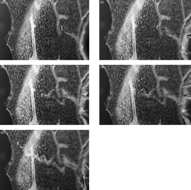
We have used both high-resolution stereo transmitted light microscopy (Fig. 1a–e) and high scan speed (video rate or higher) confocal reflection microscopy with video tape recording to study crack initiation and propagation in wet equine distal MC3 samples prepared to leave single trabeculae as test elements. Microcracks show up as high-contrast features in reflection mode confocal scanning laser microscpy (CSLM). High-resolution real-time 3D confocal microscopy is achieved with white light illumination and special objective lenses designed to give a defined range of linear longitudinal chromatic dispersion (Maly & Boyde, 1994).
Fig. 1.
Dynamic 3D LM study of fracture initiation and propagation in isolated equine Mc3 trabeculae. One side of stereo-pair images. 10× water-immersion objective, Edge 3D microscope.
2D quantitative backscattered electron SEM
For block surface techniques, samples were embedded in poly methyl-methacrylate (PMMA) after ethanol dehydration. In quantitative imaging using backscattered electrons (qBSE), the aim is to avoid the influence of topography upon the generation of image contrast. Blocks are finished by diamond polishing or micromilling and, before any SEM stage of examination, carbon coated. Variations in the mineral content are quantified by measuring the BSE signal under closely standardized conditions as previously described (e.g. Boyde et al. 1999c). Temporal aspects of tissue mineralization are studied by locating intravital calcein labels by CSLM: BSE and CSLM images are overlain. Distinction of pore space from solid bone is improved by combining BSE detectors with those for forward scattered and primary transmitted beam electrons (Boyde & Jones, 1996).
3D SEM
SEM of macerated plane parallel slices remains the most productive 3D method meeting requirements in resolution and width and depth of field for cancellous bone (Boyde, 2003). As already noted, the samples have been treated to remove unmineralized bone and cartilage matrix and cells. Residual problems due to ‘charging’ can be controlled by imaging with only high-energy BSE. Then the direction of apparent illumination and multiple detector positions can be employed to generate images in which colour is used to help in coding surface morphology. The limited depth of field in the SEM can be improved by taking series of images, moving the sample along the electron optic axis and combining these to generate a single extended-focus image. SEM imaging geometry gives a change in magnification with change of working distance, which is corrected for each image of the through-focus sequence. Excellent 3D imagery is achieved through recording and replaying a set of images taken with a small tilt angle difference (Boyde, 2003; website www.anat.ucl.ac.uk/research/boyde).
We have used both stereo-pair secondary electron (SE) SEM images and multiple viewpoint BSE projections of human lumbar vertebral trabecular bone samples tested to the inception of failure in a three line bending rig (Jayasinghe & Boyde, 1993).
Findings
Cracks and microdamage
Three-dimensional optical microscopy via oblique illumination improves the means for seeing cracks in a correct 3D context, and may be more useful in future studies than real-time conventional transmitted and confocal reflected light microscopy in monitoring crack generation in in vitro experimentation – where we can show fatigue microcrack generation after prolonged, repetitive flexing that indubitably exceeded physiological strain levels (Fig. 1a–e). These optical microscopical methods all provide the opportunity to keep the sample fully hydrated. Using them, we have searched in vain for microcracks which might have good credentials in respect of having been generated in vivo.
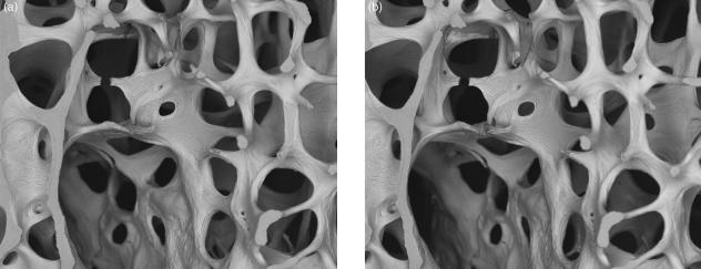
The cracks resulting from our mechanical loading tests on contrived vertebral body trabecular bone slices were generated in damp, but not dry tissue. Three-dimensional studies of the paths taken reveals a complexity that would be very frustrating to analyse (Fig. 2, stereo-pair). This probably stems from the convolution of attempts for cracks to take shortest paths, to follow potential interlamellar cleavage planes and cement lines and, as we have speculated, also non-cement cement lines, i.e. those with non-mineralized matrix in the plane of the join of newly apposed bone to a prior, well-mineralized resting surface. These latter defective ‘cement’ lines accumulate in old human bone. The surface to which new bone is attached is, in addition, very often not resorbed, so that there is also no mechanical interlock between old and new (see, for example, figures 20 and 21 in Jayasinghe et al. 1993). We sometimes see separation at such lines in 2D BSE SEM of PMMA-embedded tissue. To demonstrate a trend to an increase in this feature with age, we used a three-line bending test for stiffness of L4 slices before and after treating them with H2O2 solutions to dissolve the non-mineralized matrix in the fault planes, and showed a much greater reduction in older individuals – in keeping with the SEM evidence (Jayasinghe & Boyde, 1993; Jayasinghe et al. 1993; Boyde & Jones, 1998).
Fig. 2.
20-kV stereo pair BSE image of three-line bending test sample of fourth lumbar vertebral body trabecular bone, showing the very complex fracture path. Tilt angle difference 8°. Field width, 4.45 mm.
Crack artefacts in SEM
Extensive study of bone from wide-ranging sites in many mammalian species by backscattered electron imaging of PMMA- or other resin-embedded tissue shows cracks, all too frequently. Most of these can be safely attributed to the artefacts of sample preparation, especially shrinkage induced by ethanol dehydration. Contraction during early oligomeric stages of polymerization of an embedding resin will lead to development of cracks that are also filled with resin and also appear black in both SE and BSE imaging modes. Shrinkage in late stages of polymerization and due to the super-desiccation of imperfectly dehydrated bone tissue in the vacuum of the SEM specimen chamber leads to empty cracks without any conductive coating and which therefore charge under electron irradiation and appear anomalously bright in the SE mode. Usually, however, they will appear black in BSE mode unless the problem is exceptionally severe.
Some real cracks are infilled and appear white in BSE SEM
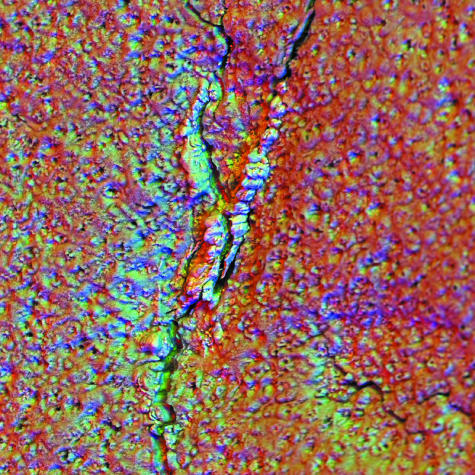
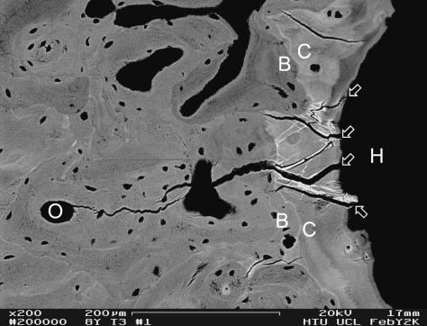
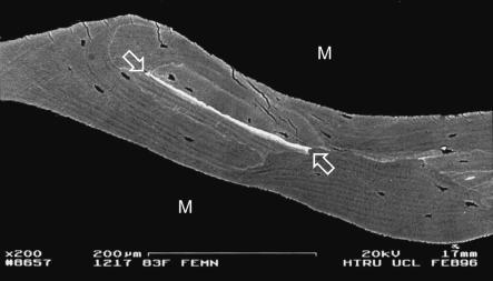
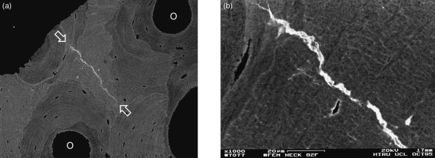
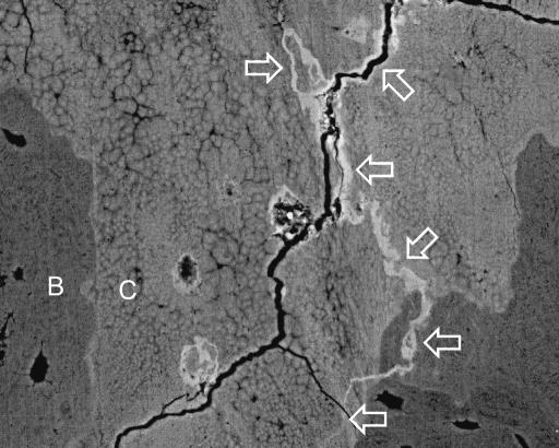
BSE SEM study of equine articular calcified cartilage (ACC Fig. 3) and aged human bone (Figs 4–9) shows cracks that developed in vivo and that they also repaired in vivo by the intercalation of densely mineralized matrix. These are seen in lamellar bone and in articular calcified cartilage (ACC) and calcified fibrocartilage (CFC). We have also seen large numbers of calcified cracks in ACC and the immediately subchondral bone (SCB) in first phalanxes, third metacarpals and metatarsals, carpals and tarsals in young and older horses subjected to overload exercise regimes. We have seen an association with such calcified cracks and sharp concavities in the ACC mineralizing front (tidemark) surface, which would tend to ‘open’ under load.
Fig. 3.
Medial condylar groove of 2-year-old Thoroughbred racehorse from MUGES training study, hyaline articular cartilage removed to the level of the mineralizing front (MF) of ACC using Tergazyme, carbon-coated, 20-kV SEM. BSE images recorded with three 90° sectors of annular solid-state BSE detector are used as RGB components (Boyde, 2003). Calcified material has filled a crack in ACC and is slightly proud of the MF. Field width, 900 µm.
Fig. 4.
20-kV BSE image of 8-year-old Thoroughbred racehorse third tarsal bone, showing MF of ACC at right-hand side. Note the (white) densely mineralized cracks within the ACC (arrows). Other post-mortem tissue processing cracks in ACC and SCB are black. Scale bar in image.
Fig. 9.
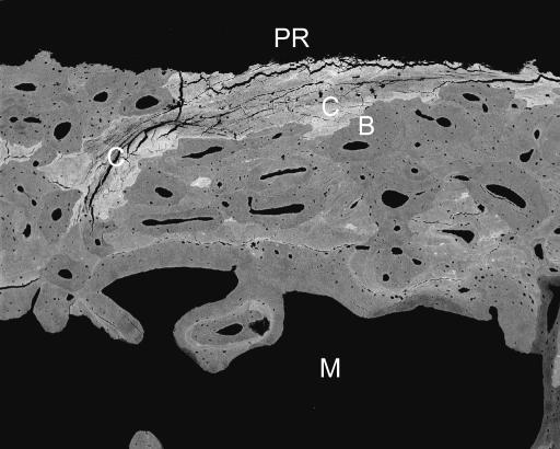
Human femur, 88-year-old female, part of large bone removed at operation from subcapital fracture case, showing calcified fibrocartilage (C) at periphery of cortex with numerous fine cracks (dark lines). 20-kV BSE of PMMA-embedded, polished, carbon-coated sample. Field width, 1780 μm.
Repair of artificial materials, autograft and allograft
In studies of repair mechanisms in large segmental defects in the sheep tibia repaired with porous hydroxyapatite ceramic (HAC) material, it was evident that the HAC was really subject to microdamage cracking during normal functional usage. These cracks were again repaired by the intercalation of new bone, but here it was mostly similar to normal bone tissue in its degree of mineralization and we presume that it has a collagen-rich matrix (see figures 3e,f and 4a in Boyde et al. 1999a). The ability of bone cells to work to produce bone seams in such confined spaces is nothing less than wonderful. The same phenomenon is also observed within compact cranial bone (external table of the parietal) grafts harvested by a special impacting, ‘bulldozing’ tool designed to generate large numbers of microcracks at acquisition. Many of these microcracks healed and sealed by bone deposition of first intent, there being no prior resorption. It is also of import that this very rough handling of the bone tissue – deliberately designed to induce microcracks so that sheets of bone could be rolled up and unrolled again (see figure 3 in Boyde et al. 1990) – did not evidently induce bone cell death: yet one current and popular mode of thinking in this field is that much less serious damage to bone matrix will damage the resident cells, and that this is in some way connected with ‘eat me’ signalling (Noble et al. 2003). However, dead bone also works well as a graft material (Wong, 2000).
Vital microscopy in the rabbit tibia
In vivo, we could see that separations that developed between an optical glass window and the titanium window frame in rabbit tibial shaft bone also showed intercalated thin films of mineralized repair material. Here, the implanted material, particularly the optically smooth glass, could separate more than once from the bony attachment studs that contacted it, and several layers of the infilling phase could accumulate in an incremental fashion (see figures 4b,e,f and 5c in Boyde et al. 1995b).
Fig. 5.
Human femoral shaft, post-mortem, compact bone adjacent to metal implant stem, showing densely mineralized crack (between arrows in b). 20-kV BSE of PMMA-embedded, polished, carbon-coated sample. Scale bar in a.
Osteocyte death and mineralization: one fate of the apoptotic cell
What can be definitively said regarding the fate of dead osteocytes? The most solid evidence that a cell is dead is that its lacuna is mineralized (Figs 10–12). Calcification of apoptotic debris (or the cell mummy) would be a rapid and effective way of removing dangerous fragmented DNA. So why do more?
Fig. 10.
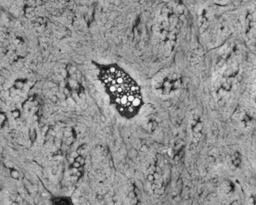
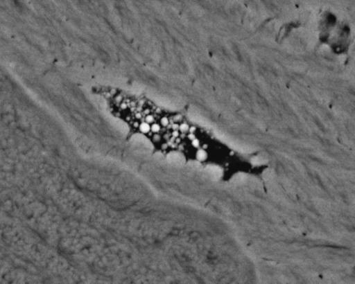
Human femoral shaft, post-mortem, compact bone adjacent to metal implant stem, showing mineralized apopototic debris in osteocyte lacuna in Sharpey fibre bone. 20-kV BSE of PMMA-embedded, polished, carbon-coated sample. Field width, 44 µm.
Fig. 12.
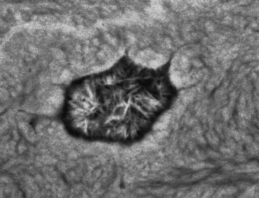
Human femoral shaft, post-mortem, compact bone adjacent to metal implant stem, showing mineralized osteocyte lacuna with large crystals. 20-kV BSE of PMMA-embedded, polished, carbon-coated sample. Field width, 22 μm.
Osteocytes die and calcify in young normal bone (see figures 9 and 14 in Jones et al. 1999) as well as in ageing bone: in the mandible, relatively large tracts of bone contain mineralized osteocytic lacunae and canaliculi (see Figure 4a–c in Kingsmill & Boyde, 1998): the same is true for auditory ossicles (Maconnachie et al. 1985), and we have a large number of other examples from post-cranial sites. Again, next to nothing is known about osteocytic mineralization mechanisms, but the phenomenon has obvious potential parallels with fine crack healing in bone and ACC.
Fig. 14.
Lumbar vertebral body trabecular bone, 89-year-old female, showing microcallus repair of trabecular microfractures. Field widths, 850 µm.
Some cracks that are not artefacts are black in BSE SEM
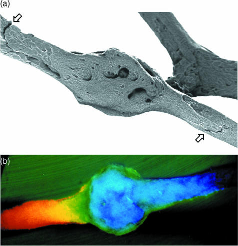
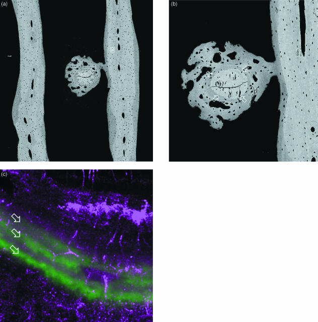
Repair of microcrack damage in over-exercised (‘trained’) equine bone trabeculae can occur by rapid deposition of local lamellar bone repair tissue ‘bandaging’ the affected part, without intervening resorption, and backed up by more frankly woven bone tissue. In the instance shown in Fig. 13, we had the good fortune to bracket the event with fluorescent (calcein) calcification markers, so that it was discovered by wide-field, real-time confocal fluorescence survey, followed by quantitative BSE imaging. The morphology is similar to single-rod trabecular ‘microfractures’ in older human material.
Fig. 13.
Fracture of transverse rod (centre) in parallel plate (each side of field) trabecular bone of 18-month-old Thoroughbred racehorse from the Bristol treadmill exercise training experiment, approximately 20 mm from distal articular surface. (a,b) 20-kV BSE SEM of central medio-lateral frontal section. (a) Field width, 1643 µm; (b) different micromilling level, old broken rod between four arrows, Field width, 530 µm. (c) Combined reflection (purple = red & blue) and fluorescence (calcein green, arrows) confocal image, showing 24-h increments of lamellar bone formed in initial repair process of this microfracture. Field width, 74 µm.
We have imaged a large number of examples of ‘bandaged microfractures’ in human trabeculae (Fig. 14a,b), but mostly in 3D in macerated samples where we cannot always prove that there was no resorption prior to formation. However, counter to the widely broadcast simplistic view, absence of site-specific coupling is in fact so much the norm in aged human bone that it would be surprising if such events were resorption coupled (Boyde, 2002b, 2003).
Densification in response to exercise in thoroughbred horse distal cannon bone
Distal parts of Mc3s were obtained from controlled training experiments in which 18-month-old or 2-year-old Thoroughbreds were subjected to strongly contrasting exercise routines. Mc3s were sliced longitudinally in parasagittal or central and dorsal- and palmar-oblique medio-lateral planes, embedded in PMMA, the blocks micromilled and carbon coated, and the bone mineralization density studied at the cubic micrometre scale using qBSE. Entire bone slices were analysed using automated scanning of subfields. For each subfield, anatomical region and whole slice, bone volume fraction (BVF) was calculated with mean and median BSE grey levels: volume fractions of 16 density phases were estimated.
We found distinct patterns of regional variations in bone density throughout the distal condyles of Mc3. Bone density was greater in specimens from exercise groups than in those from controls by computer tomography (CT), and by radiographic density of both whole bones and thick and thin slices. Precise BVFs were given by qBSE. The most important change was in the increased amount of bone deposited within antecedent marrow space in cancellous tissue in the exercise group compared with controls.
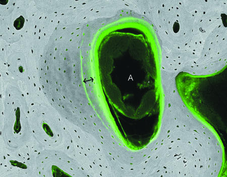
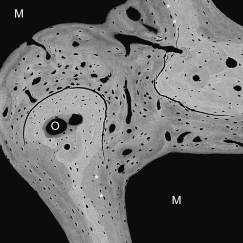
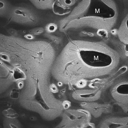
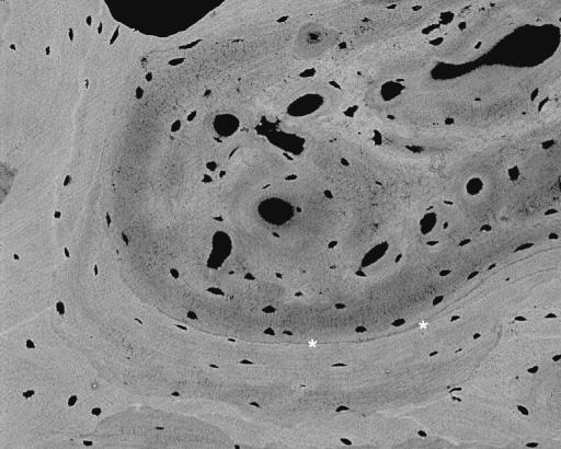
The BVF densification in the trained animals involved the new formation of lamellar bone on resting surfaces, without prior osteoclastic resorption, but was accompanied by immature bone formed in the larger compartments of prior marrow space as strands and sheets with more highly mineralized centres (Figs 15–18). The bulk of the newly formed bone had the lower density characteristic of newly mineralized lamellar bone. Thus the more loaded zones have a higher BVF, but a lower level of mineralization, implying (i) that the more solid bone fabric is, at least initially, made of a more compliant material and (ii) that clinically applicable X-ray methods will underestimate the resultant increased BVF. The large volumes of new bone filling prior marrow space formed in the exercised groups of animals were deposited rapidly and at rather short notice: they include, at the time of their formation, complexes of fine blood vessels. [Hausman et al. (2001) found that the inhibition of growth of microvasculature stopped bone wound healing.] Whereas new bone packets joined to older lamellar bone always show highly mineralized cement lines by BSE imaging, we found a poorly mineralized (dark) line to delineate the new bone: the tissues tended to part at this join in post-mortem tissue processing. It would be very interesting to know the extent to which this separation may occur in life.
Fig. 15.
20-kV qBSE image of distal third metacarpal bone from Thoroughbred racehorse from the MUGES training study: image is combined with confocal fluorescence image to show calcein label groups, 3 weeks apart (double arrow), and histology in marrow space compartment: note the large arteriolar blood vessel (A). Field width, 1.3 mm.
Fig. 18.
20-kV qBSE image of distal third metacarpal bone from Thoroughbred racehorse from the Bristol treadmill training study, showing infilling of prior marrow space with new bone, without prior resorption and with new woven bone strands in centre of prior marrow space. Tissue processing and super drying in SEM caused cracking at the junctions of new with older trabecular bone tissue. Asterisks mark poorly mineralized join lines with older lamellar bone. M = marrow space. Field width, 900 μm.
In the immediate subchondral bone zone, the open canal or marrow space was much less in the exercised groups, whereas extensive spaces representing resorption episodes that extend into the deep ACC were more easily seen in the control group.
Sclerosis of the SCB in the palmar aspect of both medial and lateral condyles may occur as an adaptive response to increase in strain associated with the onset of vigorous training. We found no evidence for the alternate view that it may represent a resorption-coupled reparative process following damage inflicted by the increased loads associated with high-speed exercise. As a consequence of the remodelling process, bone forming the distal condyles of the Mc3 is likely to be significantly stiffer than that in the sagittal ridge. The excess stiffening within the condyles due to extensive new bone formation may lead to concentration of strain at the condylar grooves and be partly responsible for incipient cracking through ACC and into the SCB, which is part of the complex leading to catastrophic fracture (Riggs et al. 1999a,b).
Periosteal regions that showed extensive and active resorption as part of the modelling through waisting of the bone showed arrest of resorption and active new bone formation. Regions where bone formation dominated in the unexercised control groups show dramatic new bone formation, with the well-known sprouting of new woven bone-centred ridges enclosing and defining primary osteonal spaces that infill with lamellar bone.
Discussion
On the difficulty of establishing any association between microcracks and resorption in compact bone
It is obvious that microcracks in bone will be removed with the bone microvolume that contains them – if and when it is resorbed – and the calcified tissue that contained the crack will be replaced by newly made tissue, which is initially perfect.
The assumption of site coupling has to be correct within compact bone, because only by removing some bone tissue can more be replaced in the same domain: if it is not replaced, then the tissue will become porous or cancellous. If cracks do happen, they are more likely to accumulate in older bone. Older bone contains domains that have been in existence for a longer time, will be more highly mineralized at the fabric level and therefore be stiffer, more brittle and more liable to crack. However, these considerations do not establish that microcracking signals any need for replacement.
Martin (2002) suggests that all resorption in compact bone may start in cracked domains. For this to be proven, there has to be some incontrovertible verification of the existence of microdamage, but any evidence must always have been removed from the scene, giving rise to an insoluble circular argument.* Martin argues that it is possible that his hypothesis is true. His case seems to rest to some extent upon the dimensions of secondary osteons in the cortices of large cylindrical bones. Unfortunately, he gives no definition of osteon. If we follow textbooks, we will most probably find a definition that includes the characters of a set of concentric layers of bone (lamellae) surrounding a (‘Haversian’) canal containing a (neuro)vascular bundle (Williams et al. Gray's Anatomy, 37th edn, 1989). Textbooks call the more transverse elements of the system of vascular channels in compact bone ‘Volkmann’s’ canals, but there is a continuum of orientations of such canals, albeit more are longitudinal than having any other definable direction. The space containing the capillary bed in compact bone is continuous, with the only expected blind ends being those of those cutting cones that are not exploiting the course of a previously existing canal, although many do follow old paths. The osteonal canals are continuous with openings at periosteal or endosteal surfaces. If trabecular (cancellous, spongy) bone is present, there is a grading of properties such that wide bore marrow spaces taper to become narrow-bore Haversian canals, so that there is no hard and fast border between compact and cancellous tissue. It is difficult to pronounce where a canal begins or ends. If the start of the definition of osteon is correct, then the end of cannot be found, and one cannot measure, and should not base mathematical theorems upon, its length. However, to offer some support for the concept of a spatially (and from the developmental aspect, temporally) limited osteon, we recognize that the unit described as a packet in cancellous bone has some reality too in compact bone. We should not threrefore argue from osteon, but from packet length. Packets are complex in compact bone (as they are too in cancellous bone), and branch at branching points of the capillary bed.
Microfractures in trabeculae are not resorbed away in the first instance: they are bandaged
In the spongy bone of human vertebral bodies and elsewhere, small transverse breaks are mended by the application of an encircling patch or bandage of either lamellar or woven bone (microcallus) tissue, and in neither case is osteoclastic resorption implicated in a first step. In the example shown in Fig. 12, the broken rod is repaired by lamellar bone, backed up by microcallus, with no resorption. It is clear that microfractures are not removed by resorption in the first instance in cancellous bone and a whole mechanism exists for consolidating cancellous bone that avoids or bypasses this potential need. This involves the dual processes, in response to strenuous load bearing exercise, of (a) lamellar bone deposition on existing non-resorbed surfaces bounding marrow spaces and (b) massive infilling, beginning as woven bone sheets and strands, continuing to become lamellar: (a) and (b) join up to obliterate the prior marrow cavity. Finally, secondary osteonal canals develop within the previous and now massive trabecular plates. ‘Cutting cones’ within prior trabeculae might eventually become sufficiently expansive that they make a new replacement marrow space within a tissue which would otherwise be too dense.
The basic fuchsin crack staining (and generating?) protocol
It would be desirable for work in this field that the sample not be subjected to any procedure that might initiate cracking. Cracks are very likely to develop during the standard basic fuchsin staining regimes used to monitor defects in mineralized bone matrix because the dye is dissolved in ethanol (Burr & Stafford, 1990; Burr & Hooser, 1995; Mori et al. 1997; Boyce et al. 1998; Burr et al. 1998; Lee et al. 1998; O’Brien et al. 2000; Frisch et al. 2001). Several authors using this method have noted improved discrimination when the stain is studied by conventional epifluorescence or confocal epifluorescence microscopy (Boyce et al. 1998; Burr et al. 1998; Fazzalari et al. 1998a; Lee et al. 1998; Huja et al. 1999; Reilly & Currey, 1999; O’Brien et al. 2000; Frisch et al. 2001; Zioupos, 2001).
There is an advantage to be expected from confocal microscopy in studying microcracks if the thin section preparation is avoided by looking at whole blocks. Aqueous must be preferred over ethanolic stain solutions. However, it is not excluded that some of the finer spaces penetrated by fluorescent dyes are none other than ‘ground substance’ space between collagen fibrils and fibre bundles, and that the dye is pumped there by repetitive loading cycles. Ultra-microcracks (Fazzalari et al. 1998a) need not be other than, perhaps exaggerated, normal fine structural boundaries within the hard tissue matrix. The better evidence for damaging effects of repetitive in vitro loading comes from changes in global mechanical properties, as demonstrated by Reilly & Currey (2000).
Measuring the deformation of unembedded blocks during preparation for LM, SEM or transmission electron microscopy (TEM) study has shown that no measurable dimensional change is to be expected when soft tissue samples are immersed in 70% (v/v) ethanol (Boyde & Maconnachie, 1979). Below this concentration, certain tissues may swell markedly – depending upon tissue and fixation type – but such swelling is minimal and transient if the first immersion is in 70%. Serious shrinkage and hardening in all tissues begins in ethanol concentrations greater than 70% by volume. In any mineralized tissue, this is constrained by the deposition of the bone salt (mineral, carbonate apatite), which replaces some of the water-filled space in the hydrated protein matrix. However, the water is never entirely replaced and the protein matrix never entirely disappears, not even in the case of fully mature dental enamel. The removal of water thus induces internal stressing within bone, and it may crack. We do not have the necessary data for bone in dilute aqueous solutions. Possibly it swells. It is, however, certain that it shrinks when the dielectric constant of the ambient liquid phase falls to values found for ethanol and many other non-aqueous solvents used in conventional tissue processing. All tissues harden ‘in spirit’. We do not have measurements for bone, but a better polish can be achieved (on ‘wet or dry’ abrasive papers) with unembedded bone slabs and slices wet with ethanol, methanol or xylene than those wet with water, and the edge finish of trabeculae is much neater, reflecting the hardening of any osteoid or superficial, less well mineralized bone. Thus we anticipate bone cracking in ethanol. We would also expect more cracking on dehydration if the bone were unequally mineralized or demineralized: intentionally, Yeni et al. (2002), or unintentionally, e.g. Schaffler et al. (1994), who ‘stained’ with lead-uranyl acetate, a demineralizing agent.
The converse: could swelling in unsalted water damage bone? Bones do not normally contact fresh water in life, but some bone-like tissues do. Mammalian teeth that have lost any protective covering of enamel have exposed oral surfaces of cementum or dentine that regularly contact water. Large surface areas of both cementum and dentine are exposed in artiodactyls, perissodactyls, elephants and odontocetes – and of course in those members of the human species ‘getting long in the tooth’. Cementum is tooth bone. In the packing and binding variety that joins tooth plates together in herbivorous mammals, the net collagen orientation is rather randomized and one would predict that it would always present a fair proportion of fibres running in such a direction as to come under tensile load and to resist any resultant swelling pressure (Jones & Boyde, 1974). In this respect, it is very like ‘average’ bone. However, in the attachment cementum, which is the type exposed at the necks of human teeth, a very different circumstance prevails. The bulk of the collagen is perpendicular to the tooth surface (Jones & Boyde, 1972). When this tissue type dries, it may crack because there is no surface-parallel collagen to resist cracking. The underlying dentine, by contrast, has a randomized collagen orientation, mostly as a feltwork with the fibres parallel with the (formative, predentine) tooth surface, and is more resistant to cracking (Jones & Boyde, 1984).
3D optical microscopy in searching for microcracks in vivo and in vitro
We have conducted two (unpublished) studies in which we have attempted to visualize microcracking using improved optical detection means. In the first, we prepared single trabeculae attached to large handles of bone, exploiting the special parallel plate trabecular zone of the equine cannon bone (Boyde et al. 1999b). This permitted us to bend the selected element back and forth whilst under inspection in a real-time direct view high-resolution 3D optical microscope. Three-dimensional still images could be recorded of the scene before and during genuine microcrack evolution in bone wet with physiological saline.
In another study, we followed the basic fuchsin staining protocol, but we prepared rather thick slices for study to minimize the risk of damage after staining. We used another means of generating the 3D image, one that uses motion parallax to display 3D information and is therefore portable to dynamic presentation using PowerPoint projection. We can see microcracks when they are there with this method, but we have been unable to find any in equine cannon midshaft. Others have shown genuine microcracks generated in in vitro situations: most of these experiments reflect supra-physiological loading regimes that would never be encountered in the normal life of a normal bone.
Not all is well in SEM
The cracking problem is common to all preparation protocols for undemineralized tissues irrespective of the mode of microscopic examination of the tissue. The results are most obvious for SEM samples, because the method generally has contrast mechanisms and resolution in hand, enabling the resulting microcracks to be visualized. A good example concerns the charging (what might euphemistically be called ‘beam-induced voltage contrast’) seen in secondary electron emission mode images of dried, unembedded bone samples. The cracks in unembedded bone matrix surfaces, which ‘charge’ in SE mode, can be made invisible by altering the surface potential to +200 V to prevent the escape of SE or by imaging with fast BSE (see figures 7.14 and 7.16, p. 289 in Boyde, 1984).
Fig. 7.
Human femoral neck, 83-year-old female, post-mortem, trabecular bone showing densely mineralized cement line material, 20-kV BSE of PMMA-embedded, polished, carbon-coated sample. Scale bar in image.
In the preparation of bone samples for qBSE imaging, bone tissue is further embedded in a polymer, the monomer of which is infiltrated into the tissue, eventually replacing that which was water or ethanol or any other intermediate solvent. Methyl methacrylate is in common use for this purpose, as well as for LM histology. Both (1) oligomerization and (2) polymerization of the monomer involve substantial contraction of the MMA. (1) Oligomerization may cause cracking, but the cracks may fill with viscous oligomer and cannot be distinguished from cracks that may have formed during ethanolic (or other) dehydration. (2) Shrinkage of the very viscous to semisolid PMMA may cause cracks that are empty in the final block. They would be expected to be unstained in the basic fuchsin LM protocol, and are simply annoying if they occur in the SEM sample. As a final problem for BSE SEM, a sample that escaped shrinkage-induced damage before it goes into the SEM can be so damaged in the SEM. This happens if the dehydration was not perfect, when firmly bound structural water of the bone collagen matrix can escape into the vacuum space, again causing empty cracks. These are recognized because they can be seen where they were not, and because they cause breaches in the continuity of the (carbon) surface conductive coating, leading to the phenomenon of island charging seen in SE images. Shrinkage of embedded samples will never be as great as that incurred in the real drying of unemebedded samples intended for 3D SEM. Although it is possible to examine fully hydrated samples in the water vapour pressure controlled sample chambers of environmental SEMs (ESEM), the sample is essentially swamped in water, which is mostly what will be seen, and the field of view is strictly limited by the pressure-limiting aperture (Boyde & Jones, 1996).
Thus, some of the authentic cracks seen in SEM may not be so genuine after all, but there is no smoke without fire. A frequent finding in BSE SEM is of microcracking within any exceptionally dense phase surrounded by normal, less dense bone, and cracking between one and the other. An important case concerns microcracking within calcified fibrocartilage residues in the external surface of the femoral neck cortex (Fig. 9), which may be very important in nucleating and propagating the initial crack, and leads on to the subcapital femoral neck fracture in the elderly osteoporotic individual. Fine crazing is seen in the CFC in the bone of the crest of the iliac crest, and generally in old hypermineralized resting cement-line surfaces and between these and the new bone deposited upon them. Another common example concerns the splitting – no doubt artefactual – that may develop between better mineralized, pre-existing trabecular bone and the less well mineralized, new lamellar bone ‘dumped’ on to it, without prior resorption, in the rapid response to overload exercise (Fig. 16).
Fig. 16.
Same block as Fig. 13, low-magnification confocal laser scanning fluorescence image to show infilling of prior marrow space with new bone, which shows a brighter fluorescence level. M = residual marrow space. Field is 7 mm deep to medial condylar groove. Field width 2 mm.
Some cracks do obey the golden rule: experimental surgery
In studies of healing of retrieved fragments of human bone grafts made with autologous transplants derived from the external table of the parietal bone, we could show clear examples of the crack exploitation. Some cracks deliberately introduced by the initial graft harvesting procedure were opened by resorption and repaired by new bone, which joined the fragments together. In many other cases, however, new bone was deposited directly on the crack surfaces (just as happens with sterile fracture fragments), thus uniting them without the intervention of resorption (Boyde et al. 1990).
Crack sealing and healing by exceptionally thin seams of highly mineralized matrix in calcified cartilage and bone
Cracks are commonly sealed and healed (annealed) by the inclusion (intrusion) of highly mineralized matrix in articular calcified cartilage and older and better mineralized bone.
Healed cracks in compact lamellar bone are particularly seen in interstitial regions of old osteonal systems. I have encountered them regularly in the femoral shaft cortex surrounding metal implant stems and in femoral neck samples from elderly individuals. Not always, but not uncommonly, regions with calcified microcracks also have calcified canaliculi and thick layers of hypercalcified material in the walls of the osteocyte lacunae.
This pattern of calcification of lacunae is distinct from others, as follows. Lacunae at any age may show calcification of apoptotic debris of the osteocyte marked by very dense spherical ‘pearls’ (Fig. 10). Some calcified lacunae are mineralized more uniformly, and it is sometimes possible to discern the morphology of the osteocyte within the calcified material in negative contrast: it is tempting to speculate that such osteocytes died without significant autolysis. In both cases, the potential danger of floating DNA fragments is avoided by wrapping it up beyond detection by calcification. Sometimes one will encounter large (nearly 1 µm wide and several micrometres long) crystals within lacunae with no evidence of morphology attributable to cell remnants (Fig. 11).
Fig. 11.
Human femoral shaft, post-mortem, compact bone adjacent to metal implant stem, showing mineralized apopototic debris in osteocyte lacuna in lamellar bone. 20-kV BSE of PMMA-embedded, polished, carbon-coated sample. Field width, 44 µm.
Healed hypercalcified cracks in ACC, beginning (or ending?) at the tidemark mineralization front (MF), are common in ‘trained and racing’ Thoroughbred racehorses. They have been encountered in all those regions of the bones that we elected to study, which include proximal first phalanx, distal third metacarpal and metatarsal, and carpal and tarsal bones. In PMMA-embedded samples studied by BSE SEM, microcracks in ACC are mostly perpendicular to the MF, i.e. parallel to the direction of the grain of the principal orientation of the cartilage collagen, although more oblique orientations are found. A common location for such cracks lies in densely mineralized patches focused in the depths of grooves in the front.
We have shown that the common distal condylar fractures of the equine third metacarpal (cannon) bones begin by the process of cracking in ACC, which is usually focused in the depths of the condylar grooves (Riggs et al. 1999a, b). When such a crack propagates inwards into the SCB, it will commonly be expanded by osteoclastic resorption prior to new bone deposition in the repair process. This leaves the bone weakened, and susceptible to catastrophic crack propagation into the parallel plate trabecular zone (Boyde et al. 1999b; Riggs et al. 1999a, b).
Natural history from surgical retrieval shows examples in which non-vital tissue fragments or fragments of implanted artificial (bio)materials are united by bone deposited into seams that are so thin that it is difficult to conceive that osteoblasts working therein would have ‘been comfortable’– at least there would have been no space for other cells and capillaries. In experiments involving the implantation of polished optical glass windows in titanium frames into the medial tibial plateau of adult rabbits, it was found that the stress-protected cortex remodelled to become spongy bone with only a few bony processes contacting the glass or Ti (Boyde et al. 1995a). These ‘feet’ occasionally detached from the stiffer implant, but were rejoined to the glass or Ti by an extremely thin layer of calcified tissue. This process could be seen to have repeated several times, leading to incremental layers of new ‘bone’ grown towards the implant.
In experiments with HAC, large cylinders replaced segmental defects in ovine mid-shaft tibia up to 35 mm long. After initial healing, functional load applied to the HAC caused microcracking, and cracked fragments were re-united with bone (Boyde et al. 1999b). Similarly, the finest nooks and crannies within packed, dead, heat-treated, cancellous bone used to ‘compact’ open cancellous bone and to generate bone within the domain of the maxillary sinus prior to placement of dental implants are filled with new bone (Wong, 2000).
So what really happens to cracks in bone?
Cracks are removed when the calcified tissue in which they reside is resorbed. Some cracks are removed from the system by becoming filled with calcified matrix. Considering that relatively older bone is more likely to have been removed during a turnover cycle, the extent to which this simpler mechanism of microdamage repair occurs may be underestimated. The chemistry of the repair matrix remains a matter of speculation, but this seems to be a general repair mechanism for calcified connective tissue crack repair. In response to overload exercise in cancellous bone, damage is prevented rather than cured through infilling the prior marrow space compartment, both appositionally and de novo, without resorption. In cortical bone, the thickness of the shaft is increased in a similar pre-emptive step. In ACC, crack and calcified crack removal is delayed by deferring resorption.
Fig. 6.
Human femoral neck, 82-year-old female, compact bone removed at operation from subcapital fracture case, showing densely mineralized crack (between arrows in a). 20-kV BSE of PMMA-embedded, polished, carbon-coated sample. Field width, 387 μm.
Fig. 8.
Human femur, 70-year-old female, bone removed at operation from subcapital fracture case, showing densely mineralized crack (arrows), mostly in calcified fibrocartilage at periphery of cortex. 20-kV BSE of PMMA-embedded, polished, carbon-coated sample. Field width, 178 µm.
Fig. 17.
20-kV qBSE image of distal third metacarpal bone from Thoroughbred racehorse from the Bristol treadmill training study, showing infilling of prior marrow space with new bone, without prior resorption and with new woven bone strands in centre of prior marrow space. Asterisks mark the poorly mineralized join line with older lamellar bone. Field width, 588 µm.
Acknowledgments
I thank SRC, MRC, SERC, EPSRC, the Wellcome Trust and the Horserace Betting Levy Board for substantial financial support, and the many collaborators listed in Table 1 for help in providing very well-documented research material. Mo Arora and Roy Radcliffe have provided excellent technical assistance and I am also deeply indebted to my colleagues Sheila Jones and Peter Howell for all their help and friendship.
Footnotes
’Secondary osteons’ form in calcified tissues other than bone, including calcified ligaments and tendons, calcified hyaline cartilage and calcified fibrocartilage and in dentine in the Pacific spinner dolphin,Stenella longirostris (A. C. Myrick, personal communication).
Labels used in illustrations
*Poorly mineralized join line between old and new bone (non-cement cement line)
A lumen of arteriole
B bone
C calcified articular cartilage or calcified fibrocartilage
H hyaline articular cartilage
M marrow space in bone
O osteonal canal space in bone
PR periosteal resorbed surface
References
- Bathe AP, Collings AS, Boyde A. Ex-vivo study into the microstructural effects of extracorporeal shock wave therapy on equine bone. Proceedings of the European College of Veterinary Surgery.2001. [Google Scholar]
- Bathe AP, Boyde A. Morphometric studies of distal tarsal bone modelling in Thoroughbred racehorses. J. Bone Min. Res. 2002;17:942. (Abstract OC2). [Google Scholar]
- Bentolila V, Boyce TM, Fyhrie DP, Drumb R, Skerry TM, Schaffler MB. Intracortical remodeling in adult rat long bones after fatigue loading. Bone. 1998;23:275–281. doi: 10.1016/s8756-3282(98)00104-5. [DOI] [PubMed] [Google Scholar]
- Boyce TM, Fyrhie DP, Glotkowski MC, Radin EL, Schaffler MB. Damage type and strain mode associations in human compact bone bending fatigue. J. Orthoped. Res. 1998;16:322–329. doi: 10.1002/jor.1100160308. [DOI] [PubMed] [Google Scholar]
- Boyde A, Maconnachie E. Volume changes during preparation of mouse embryonic tissue for scanning electron microscopy. Scanning. 1979;2:149–163. [Google Scholar]
- Boyde A. Methodology of calcified tissue specimen preparation for scanning electron microscopy. In: Dickson GR, editor. Methods of Calcified Tissue Preparation. Amsterdam: Elsevier; 1984. pp. 251–307. [Google Scholar]
- Boyde A, Hendel P, Hendel RG, Maconnachie E, Jones SJ. Human cranial bone structure and the healing of cranial bone grafts: a study using backscattered electron imaging and confocal microscopy. Anat. Embryol. 1990;181:235–251. doi: 10.1007/BF00174618. [DOI] [PubMed] [Google Scholar]
- Boyde A, Jones SJ, Aerssens J, Dequeker J. Mineral density quantitation of the human cortical iliac crest by backscattered electron image analysis: variations with age, sex and degree of osteoarthritis. Bone. 1995a;16:619–627. doi: 10.1016/8756-3282(95)00119-x. [DOI] [PubMed] [Google Scholar]
- Boyde A, Wolfe L, Maly M, Jones SJ. Vital confocal microscopy in bone. Scanning. 1995b;17:72–85. doi: 10.1002/sca.4950170203. [DOI] [PubMed] [Google Scholar]
- Boyde A, Jones SJ. Scanning electron microscopy of bone: instrument, specimen and issues. Microsc. Res. Technique. 1996;33:92–120. doi: 10.1002/(SICI)1097-0029(19960201)33:2<92::AID-JEMT2>3.0.CO;2-0. [DOI] [PubMed] [Google Scholar]
- Boyde A, Jones SJ, Radcliffe R, Arora M, Birch HL, Wilson AM, et al. Non-explosive fracture in a cannon bone: a case report. Scanning. 1997;19:209–210. [Google Scholar]
- Boyde A, Jones SJ. Aspects of anatomy and development of bone. The nm, µm and mm hierarchy. In: Zaidi M, editor. Molecular and Cell Biology of Bone. Greenwich, CT: JAI Press Inc.; 1998. pp. 3–44. [Google Scholar]
- Boyde A, Corsi A, Quarto R, Cancedda R, Bianco P. Osteoconduction in large macroporous hydroxyapatite ceramic implants: evidence for a complementary integration and disintegration mechanism. Bone. 1999a;24:579–589. doi: 10.1016/s8756-3282(99)00083-6. [DOI] [PubMed] [Google Scholar]
- Boyde A, Haroon Y, Riggs CM. Three dimensional structure of the distal condyles of the third metacarpal bone. Equine Vet. J. 1999b;31:122–129. doi: 10.1111/j.2042-3306.1999.tb03805.x. [DOI] [PubMed] [Google Scholar]
- Boyde A, Travers R, Glorieux FH, Jones SJ. The mineralisation density of iliac crest bone from children with osteogenesis imperfecta. Calcified Tissue Int. 1999c;64:185–190. doi: 10.1007/s002239900600. [DOI] [PubMed] [Google Scholar]
- Boyde A, Riggs CM, Firth EC. Densification by infilling marrow space in response to exercise in thoroughbred horse distal cannon bone. Bone. 2001;28(5 Suppl.):S110. (Abstract P44T). [Google Scholar]
- Boyde A. Scanning oblique illumination in scanning electron microscopy and light microscopy. JAnat. 2002a;200:200. (Abstract 4). [Google Scholar]
- Boyde A. Morphological detail of aging bone in human vertebrae. Endocrine. 2002b;17:5–14. doi: 10.1385/ENDO:17:1:05. [DOI] [PubMed] [Google Scholar]
- Boyde A. Improved digital SEM of cancellous bone: scanning direction of detection, through focus for in-focus and sample orientation. J. Anat. 2003;202:183–194. doi: 10.1046/j.1469-7580.2003.00146.x. [DOI] [PMC free article] [PubMed] [Google Scholar]
- Burr DB, Stafford T. Validity of the bulk-staining technique to separate artifactual from in vivo bone microdamage. Clin. Orthop. Rel. Res. 1990;260:305–308. [PubMed] [Google Scholar]
- Burr DB, Hooser M. Alterations to the en bloc basic fuchsin protocol for the demonstration of microdamage produced in vivo. Bone. 1995;17:431–433. doi: 10.1016/s8756-3282(95)00241-3. [DOI] [PubMed] [Google Scholar]
- Burr DB, Turner CH, Naick P, Forwood MR, Ambrosius W, Hasan MS, et al. Does microdamage accumulation affect the mechanical properties in bone? J. Biomech. 1998;31:337–345. doi: 10.1016/s0021-9290(98)00016-5. [DOI] [PubMed] [Google Scholar]
- Fazzalari NL, Forwood MR, Manthey BA, Smith K, Kolesik P. Three-dimensional confocal images of microdamage in cancellous bone. Bone. 1998a;23:373–378. doi: 10.1016/s8756-3282(98)00111-2. [DOI] [PubMed] [Google Scholar]
- Fazzalari NL, Forwood MR, Smith K, Manthey BA, Herreen P. Assessment of cancellous bone quality in severe osteoarthritis: bone mineral density, mechanics and microdamage. Bone. 1998b;22:381–388. doi: 10.1016/s8756-3282(97)00298-6. [DOI] [PubMed] [Google Scholar]
- Frisch T, Sorensen MS, Bretlau P. Demonstration of intravital microfissures in undecalcified plastic-embedded temporal bones with the prestaining technique. Ann. Otol. Rhinol. Laryngol. 2001;110:749–757. doi: 10.1177/000348940111000810. [DOI] [PubMed] [Google Scholar]
- Frost HM. A brief review for orthopedic surgeons: fatigue damage (microdamage) in bone (its determinants and clinical implications) JOrthopSci. 1998;3:272–281. doi: 10.1007/s007760050053. [DOI] [PubMed] [Google Scholar]
- Hausman MR, Schaffler MB, Majeska RJ. Prevention of fracture healing in rats by an inhibitor of angiogenesis. Bone. 2001;29:560–564. doi: 10.1016/s8756-3282(01)00608-1. [DOI] [PubMed] [Google Scholar]
- Huja SS, Hasan MS, Pidaparti R, Turner CH, Garetto LP, Burr DB. Development of a fluorescent light technique for evaluating microdamage in bone subjected to fatigue loading. J. Biomech. 1999;32:1243–1249. doi: 10.1016/s0021-9290(99)00047-0. [DOI] [PubMed] [Google Scholar]
- Jayasinghe JAP, Boyde A. Influence of poorly mineralised trabecular bone matrix on relative bone stiffness and strength on aging and in osteoporosis. Proceedings of the 49th Annual Session Sri Lanka Association for Advancement of Science (December 1993); 1993. p. 13. Abstract A–15. [Google Scholar]
- Jayasinghe JAP, Jones SJ, Boyde A. Scanning electron microscopy of human lumbar vertebral trabecular bone surfaces. Virchows Arch. A. Pathol. Anat. Hist. 1993;422:25–34. doi: 10.1007/BF01605129. [DOI] [PubMed] [Google Scholar]
- Jones SJ, Boyde A. A study of human root cementum surfaces as prepared for and examined in the scanning electron microscope. Z. Zellforsch. 1972;130:318–337. doi: 10.1007/BF00306946. [DOI] [PubMed] [Google Scholar]
- Jones SJ, Boyde A. Coronal cementogenesis in the horse. Archs. Oral Biol. 1974;19:605–614. doi: 10.1016/0003-9969(74)90128-9. [DOI] [PubMed] [Google Scholar]
- Jones SJ, Boyde A. Ultrastructure of dentin and dentinogenesis. In: Linde A, editor. Dentin and Dentinogenesis I. Boca Raton, FL: CRC Press; 1984. pp. 81–134. [Google Scholar]
- Jones SJ, Glorieux FH, Travers R, Boyde A. The microscopic structure of bone in normal children and patients with osteogenesis imperfecta: a BSE: SEM survey. Calcified Tissue Int. 1999;64:8–17. doi: 10.1007/s002239900571. [DOI] [PubMed] [Google Scholar]
- Kingsmill VJ, Boyde A. Mineralisation density of human mandibular bone: quantitative backscattered electron image analysis. J. Anat. 1998;192:245–256. doi: 10.1046/j.1469-7580.1998.19220245.x. [DOI] [PMC free article] [PubMed] [Google Scholar]
- Labey L, Gross U, Boyde A, Hahn M, Merolli A, Meunier A, et al. Mechanical evaluation of explanted hip prostheses: technique and first results. In: Sloten JV, Lowet G, Van Audekercke R, Vander Perre G, editors. Proceedings of the 10th Conference of the European Society of Biomechanics; NFWO – publishers. 1996. p. 116. [Google Scholar]
- Lee TC, Myers ER, Hayes WC. Fluorescence-aided detection of microdamage in compact bone. J. Anat. 1998;193:179–184. doi: 10.1046/j.1469-7580.1998.19320179.x. [DOI] [PMC free article] [PubMed] [Google Scholar]
- Maconnachie E, Reid SA, Jones SJ, Lewis A, Frootko N, Boyde A. SEM studies of auditory ossicles in man and rat. Bone. 1985;6:404–405. (Abstract). [Google Scholar]
- Maly M, Boyde A. Real time stereoscopic confocal reflection microscopy using objective lenses with linear longitudinal chromatic dispersion. Scanning. 1994;16:187–192. [Google Scholar]
- Martin RB. Is all cortical bone remodelling initiated by microdamage? Bone. 2002;30:8–13. doi: 10.1016/s8756-3282(01)00620-2. [DOI] [PubMed] [Google Scholar]
- Mori S, Harruff R, Ambrosius W, Burr DB. Trabecular bone volume and microdamage accumulation in the femoral heads of women with and without femoral neck fractures. Bone. 1997;21:521–526. doi: 10.1016/s8756-3282(97)00200-7. [DOI] [PubMed] [Google Scholar]
- Noble BS, Stevens H, Mosley JR, Pitsillides AA, Reeve J, Lanyon L. Bone loading changes the number and distribution of apoptotic osteocytes in cortical bone. J. Bone Miner Res. 1997;12(Suppl. 1):36. [Google Scholar]
- Noble BS, Reeve J. Osteocyte function, osteocyte death and bone fracture resistance. Mol. Cell Endocrinol. 2000;159:7–13. doi: 10.1016/s0303-7207(99)00174-4. [DOI] [PubMed] [Google Scholar]
- Noble BS, Peet N, Stevens HY, Brabbs A, Mosley JR, Reilly GC, et al. Mechanical loading: biphasic osteocyte survival and targeting of osteoclasts for bone destruction in rat cortical bone. Am. J. Physiol. Cell Physiol. 2003;284:C934–C943. doi: 10.1152/ajpcell.00234.2002. [DOI] [PubMed] [Google Scholar]
- Norrdin RW, Kawcak CE, Capwell BA, McIlwraith CW. Subchondral bone failure in an equine model of overload arthrosis. Bone. 1998;22:133–139. doi: 10.1016/s8756-3282(97)00253-6. [DOI] [PubMed] [Google Scholar]
- O'Brien FJ, Taylor D, Dickson GR, Lee TC. Visualisation of three-dimensional microcracks in compact bone. J. Anat. 2000;197:413–420. doi: 10.1046/j.1469-7580.2000.19730413.x. [DOI] [PMC free article] [PubMed] [Google Scholar]
- Reilly GC, Currey JD. The development of microcracking and failure in bone depends on the loading mode to which it is adapted. J. Exp. Biol. 1999;202:543–552. doi: 10.1242/jeb.202.5.543. [DOI] [PubMed] [Google Scholar]
- Reilly GC, Currey JD. The effects of damage and microcracking on the impact strength of bone. J. Biomech. 2000;33:337–343. doi: 10.1016/s0021-9290(99)00167-0. [DOI] [PubMed] [Google Scholar]
- Riggs CM, Boyde A. Effect of exercise on bone density in distal regions of the equine third metacarpal bone. A study in 2 year old Thoroughbreds. In: Jeffcott LB, editor. Equine Exercise Physiology 5. Newmarket, UK: Equine Veterinary Journal Ltd; 1999. pp. 555–560. [DOI] [PubMed] [Google Scholar]
- Riggs CM, Whitehouse GH, Boyde A. Structural variation of the distal condyles of the third metacarpal and third metatarsal bones. Equine Vet. J. 1999a;31:130–139. doi: 10.1111/j.2042-3306.1999.tb03806.x. [DOI] [PubMed] [Google Scholar]
- Riggs CM, Whitehouse GH, Boyde A. Pathology of the distal condyles of the third Metacarpal and third Metatarsal bones. Equine Vet. J. 1999b;31:140–148. doi: 10.1111/j.2042-3306.1999.tb03807.x. [DOI] [PubMed] [Google Scholar]
- Schaffler MB, Pitchford WC, Choi K, Riddle JM. Examination of compact bone microdamage using backscattered electron microscopy. Bone. 1994;15:483–488. doi: 10.1016/8756-3282(94)90271-2. [DOI] [PubMed] [Google Scholar]
- Tami AE, Nasser P, Verborgt O, Schaffler MB, Knothe Tate ML. The role of interstitial fluid flow in the remodeling response to fatigue loading. J. Bone Miner Res. 2002;17:2030–2037. doi: 10.1359/jbmr.2002.17.11.2030. [DOI] [PubMed] [Google Scholar]
- Tomkinson A, Reeve J, Shaw RW, Noble BS. The death of osteocytes via apoptosis accompanies estrogen withdrawal in human bone. J. Clin. Endocrinol. Metab. 1997;82:3128–3135. doi: 10.1210/jcem.82.9.4200. [DOI] [PubMed] [Google Scholar]
- Vashishth D, Koontz J, Qui SJ, Lundin-Cannon D, Yeni YN, Schaffler MB, et al. In vivo diffuse damage in human vertebral trabecular bone. Bone. 2000a;26:147–152. doi: 10.1016/s8756-3282(99)00253-7. [DOI] [PubMed] [Google Scholar]
- Vashishth D, Verborgt O, Divine G, Schaffler MB, Fyhrie DP. Decline in osteocyte lacunar density in human cortical bone is associated with accumulation of microcracks with age. Bone. 2000b;26:375–380. doi: 10.1016/S8756-3282(00)00236-2. [DOI] [PubMed] [Google Scholar]
- Verborgt O, Tatton NA, Majeska RJ, Schaffler MB. Spatial distribution of Bax and Bcl-2 in osteocytes after bone fatigue: complementary roles in bone remodeling regulation? J. Bone Miner. Res. 2002;17:907–914. doi: 10.1359/jbmr.2002.17.5.907. [DOI] [PubMed] [Google Scholar]
- Wong K. PhD Thesis. University of London; 2000. Studies of the quality of the introsseous dental implant bed and of thermal effect in implant pathology. [Google Scholar]
- Yeni YN, Schaffler MB, Gibson G, Fyhrie DP. Prestress due to dimensional changes caused by demineralization: a potential mechanism for microcracking in bone. Ann. Biomed. Eng. 2002;30:217–225. doi: 10.1114/1.1451078. [DOI] [PubMed] [Google Scholar]
- You L, Cowin SC, Schaffler MB, Weinbaum S. A model for strain amplification in the actin cytoskeleton of osteocytes due to fluid drag on pericellular matrix. J. Biomech. 2001;34:1375–1386. doi: 10.1016/s0021-9290(01)00107-5. [DOI] [PubMed] [Google Scholar]
- Zioupos P. Accumulation of in-vivo fatigue microdamage and its relation to biomechanical properties in ageing human cortical bone. J. Microsc. 2001;201:270–278. [PubMed] [Google Scholar]


