

Abstract
Alpha helical coiled-coils appear in many important allosteric proteins such as the dynein molecular motor and bacteria chemotaxis transmembrane receptors. As a mechanism for transmitting the information of ligand binding to a distant site across an allosteric protein, an alternative to conformational change in the mean static structure is an induced change in the pattern of the internal dynamics of the protein. We explore how ligand binding may change the intramolecular vibrational free energy of a coiled-coil, using parameterized coarse-grained models, treating the case of dynein in detail. The models predict that coupling of slide, bend and twist modes of the coiled-coil transmits an allosteric free energy of ∼2kBT, consistent with experimental results. A further prediction is a quantitative increase in the effective stiffness of the coiled-coil without any change in inherent flexibility of the individual helices. The model provides a possible and experimentally testable mechanism for transmission of information through the alpha helical coiled-coil of dynein.
Keywords: physics, biophysics, allostery, coiled-coil, protein dynamics, theory
1. Introduction
Coiled-coils of alpha helices are a common structural motif in molecular biology found in several allosteric proteins as diverse as transmembrane chemotaxis receptors and the molecular motor dynein. Understanding allostery in a general coiled-coil may help explain the allosteric mechanisms of such systems. It is, therefore, of great interest to investigate how this structural motif may transmit allosteric signals in proteins. Such simple tertiary structures offer limited scope for large static conformational change. It has been suggested that information may be transmitted across a protein by changes in the internal vibrational dynamics of the protein (Cooper & Dryden 1984; Jusuf et al. 2003; Hawkins & McLeish 2004). Kern & Zuiderweg (2003) gave a recent review of evidence for such dynamic mechanisms of allostery. In the case of the DNA-binding lac repressor, a coarse-grained model gave analytically calculable changes in the lowest frequency vibrational modes on ligand binding (Hawkins & McLeish 2004). The parameters of the model were set by an atomistic simulation using optimized force-fields. The resulting changes in vibrational free energy give the dynamic part of the allosteric free energy.
In this paper we take the coiled-coil domain of the molecular motor dynein as an example system and apply the multi-scale approach outlined above to it. dynein is a molecular motor with a coiled-coil motif which transmits an allosteric signal for microtubule binding. Cytoplasmic dynein transports vesicles along microtubules and axonemal dynein is responsible for the beating of cilia and flagella. dynein is made up of one to three ‘head(s)’ with a ‘stalk’ (or ‘B-link’) which binds the (‘B’) microtubule and a ‘stem’ (or ‘tail’) which binds the cargo (or the ‘A’ microtubules in the case of flagella). The head is the central circular region made up of a ring 6 ‘AAA’ subunits. The stalk is a 15.5 nm coiled-coil which binds a microtubule at its end. The coiled-coil region is structurally conserved in all-known dynein sequences (Gee et al. 1997).
The mechanism for force generation is not entirely understood but it is thought that a conformational change due to ATP binding and hydrolysis causes a ‘power stroke’ associated with release of ADP and phosphate (Pi). The pre-power stroke is the ADP·Pi bound state and the post-power stoke state is the free (apo) one. Sliding of microtubules in flagella is also thought to be due to coordinated activity of dynein heads along the microtubules with several dynein molecules working together (Gee & Vallee 1998). The ATP binding site in the head is ∼20 nm away from the microtubule binding site at the end of the stalk, yet the binding of the microtubule is ATP sensitive. This raises the allosteric question of how the ATP binding site and the microtubule binding site communicate (Gee et al. 1997; Gee & Vallee 1998; Lindemann & Hunt 2003; Burgess et al. 2004a).
Electron microscopy images of dynein-c by Burgess et al. (2003) show differences in the conformations of the two states. They suggest an origin for the power stroke and, significantly for the present work, suggest that the stem and stalk are flexible and that the stiffness of the stalk changes depending on the nucleotide binding state. Figure 1 shows the two states of dynein with and without ADP·Vi (thought to mimic the ADP.Pi bound state pre-power stroke). Alignment of the stems in the images suggests a mean static displacement of 15 nm of the tip of the stalk. As well as this static conformational change the apparent flexibility of the stem and stalk was investigated. The stalk chord angle standard deviation in the ADP·Vi bound state is 20° compared with 11° in the apo (without ADP·Vi) state. This apo state is the state that has a higher affinity for the microtubule. One interpretation of these observed changes in standard deviation is a change in flexibility of the stalk (though there may be contributions to the scatter from artefacts of the adsorption onto the carbon surface).
Figure 1.
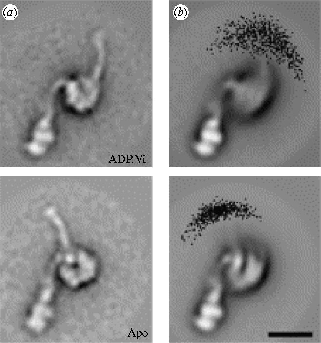
(a) Mean conformations of ADP·Vi and apo dynein-c molecules. (b) Distribution of stalk tip positions. Figure reprinted from Burgess et al. (2004a) with permission from Elsevier.
Such suggested changes in flexibility support our hypothesis that the allostery is dominated by changes in the vibrational free energy of the coiled-coil. We develop coarse-grained models, which we solve analytically to calculate these changes in vibrational free energy. We consider the relative slide of the helices, their bend and twist modes and the coupling between them. We model the binding of a ligand by a local attractive interaction between the two helices, or ‘clamping’ which restricts the degree of mutual sliding motion. The calculation shows that this increases the effective stiffness of the whole coiled-coil. In this way a small local conformational change is communicated across the long coiled-coil structure. Recent evidence supporting the idea of such a sliding mode communication has emerged from studies of the alignment of the two strands of the stalk (Gibbons et al. 2005). We use known geometrical parameters for dynein, and employ the AMBER package (Case et al. 2004) to perform computational normal mode analysis (NMA) on alpha helices to calculate values for the elastic moduli in our models.
We treat the elastic dynamics of the model in increasing detail, calculating the allosteric free energy ΔΔG in terms of the strengths of local substrate binding and the elastic properties of the helices. Section 2 introduces the overall method. Each of §§3–6 introduces another level of complexity to the problem. In §§3 and 4 we consider the simple model of two parallel rods and in the subsequent sections we consider the two rods coiled round each other. Section 3 considers sliding motion only. In §§4 and 5 we consider bending and sliding modes of vibration and in §6 we add a twisting mode. Details of parameterization are given in appendix E. At the end of the discussion (§7) we conclude by drawing out predictions and consequences of this type of modelling for experimental research programs without referring to the detailed mathematics.
2. Method
We follow the method of calculating the vibrational free energy of the lowest frequency modes of a coarse-grained model as we performed (Hawkins & McLeish 2004) for the lac repressor.
We require the elastic internal energy induced in the rods due to the strain imposed on the system by thermal fluctuations. We write this energy as , where x is a vector of all the fluctuation variables in the problem and K is a generalized elasticity matrix. Standard equations of statistical mechanics give the partition function of the fluctuating coiled-coil as
| (2.1) |
where d is the number of degrees of freedom (fluctuation variables) in the model. Note that since we are interested in free energy changes ΔG, any ‘phase-space density of states’ will cancel so they are omitted in the calculations here. The free energy is then given by
| (2.2) |
Note the second term is constant in isothermal changes so also cancels in ΔG. By comparing this free energy in different liganded states of the protein we are able to calculate the allosteric free energy communicated across the coiled-coil via the long wavelength vibrational modes. This allosteric free energy is described by ΔΔG, which we therefore calculate as
| (2.3) |
where the subscripts refer to the different liganded states as defined in §2.1.
2.1 A coarse-grained elastic model of coiled-coils
We use a coarse-grained model for a coiled-coil consisting of two alpha helices coiled round each other, which treats each alpha helix as a classical flexible rod as shown in the diagram in figure 2.
Figure 2.
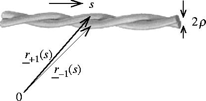
Model of coiled-coil alpha helices as two classical flexible rods with paths r±1(s) and radii ρ.
Much work has been done on the geometry and writhe of helical DNA (for example see Jülicher 1994; Marko 1998; Moroz & Nelson 1998; Rossetto & Maggs 2003) and there are clear parallels here.
In each of the following sections we write the paths of the two rods, r±1(s), as a function of the path length s along the central axis of the coiled-coil. Each rod has a Young's modulus Y and a shear modulus μ and we take the mean perpendicular separation of the centres of the helices to be 2ρ. We model the adhesive resistance to mutual sliding of the two helices with a distributed localizing harmonic potential of strength kslide(s). We restrict the form of kslide(s) to a general background constant interaction, k0 plus extra interactions at the two ligand binding sites si whose changes model ATP binding and hydrolysis at one end or microtubule binding at the other. So the force constant per unit length is given by
| (2.4) |
The force constants ki change depending on the ligand binding state in the following way:
| (2.5) |
For simplicity we set κ−1=κ1=κ. The ligand binding states are defined such that ‘++’ means both ends are ‘clamped’ (tightened) with k±1≠0 corresponding in our case to microtubule bound at the tip and ATP unbound at the other end. ‘+−’ means only the tip is clamped k1≠0 (microtubules bound) and k−1=0 due to ATP-bound. ‘−+’ means only the end attached to the head is clamped k−1≠0 (ATP unbound) but k1=0 (microtubules unbound). Finally ‘−−’ means neither end is clamped (microtubules unbound, ATP-bound). Note a ligand binding may provide the clamping or it may release the clamp depending on the details of the protein and ligand interaction in question. In the case of dynein two ligand binding sites at −l0/2 and +l0/2 give
| (2.6) |
2.2 Parameterization
We parameterize the model using values for the geometry known from electron microscopy (Burgess et al. 2003, 2004a). We estimate the Young's modulus and shear modulus from a normal mode analysis of a simple polyalanine alpha helix using the Nmode program in AMBER (Case et al. 2004; see appendix E for details). We estimate the adhesive resistance to mutual sliding k0 as being of the order typical of the hydrophobic effect. To estimate the order of magnitude of κ±1 we enhance the background hydrophobic interaction by an additional electrostatic attraction at the binding sites. The parameterization is meant to be realistic, if not necessarily exact for dynein, since details of the local interactions between the coils are not known. The goal is to calculate in principle attainable values for the allosteric free energy ΔΔG.
3. Parallel rigid rods: slide only
3.1 Model
We start very simply by considering two inextensible, rigid rods, which lie parallel side by side and are not coiled round each other. Each rod is rigid (possessing infinite bending modulus), but we allow a finite localizing potential kslide(s) between the two rods to account for adhesive resistance to relative sliding. The only fluctuation variable in this problem is the relative slide between the rods, which we call ζ. The paths of the rods are
| (3.1) |
Assuming a linear stress–strain relationship the general classical elastic internal energy of the two rods is
| (3.2) |
describing the energy due to relative displacement Δs(s) between attractive patches. The integral is over s along the path length of the coiled-coil axis. The potential due to mutual sliding is modelled by kslide(s) described in §2 (equation (2.6)). The relative local displacement between the contingent sites is in this case everywhere Δs(s)=ζ.
We then calculate the allosteric free energy from equation (2.3), giving
| (3.3) |
Calculation details are given in appendix A.
3.2 Results
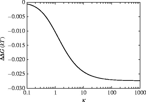
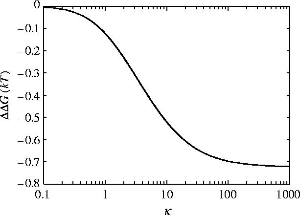
ΔΔG for parallel rigid rods (equation (3.3)) is drawn as a function of κ in figure 3 keeping all other parameters fixed for dynein from appendix E. Providing that substrate binding affects the mutual sliding potential by introducing a delta function of κ=100, significant allosteric free energies can be generated by the sliding mode alone. The electrostatic estimation of binding site attraction gives κ∼100 and ΔΔG≈−2.0kBT.
Figure 3.
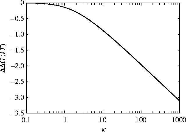
Allosteric free energy ΔΔG against clamping κ=k1/k0=k−1/k0 showing the effect of the clamping on the allosteric free energy for the model of rigid parallel rods. The values of the parameters used are those given for dynein in appendix E.
4. Parallel rods: slide and bend
4.1 Model
Now, as well as the finite potential between the rods, we allow them to bend. Each rod has a bending Young's modulus, Y. We now have two fluctuation variables c and ζ. We impose a bend fluctuation of curvature c in the positive x direction such that the rod paths become
| (4.1) |
to linear order in the fluctuation variables (see appendix B for details). Note in general there is also a bending mode in the y direction. However in this case, since it is not coupled to the sliding, it does not affect ΔG so we omit it here. Note this is not true in the coiled geometry case treated in §5.
The general classical elastic internal energy of the two rods is
| (4.2) |
where the first term describes the energy due to bending and the second terms describes the energy due to relative sliding of the two rods as in §3. Y is the Young's modulus of the rod and I is the moment of inertia about the y-axis which for circular cross-section radius ρ is . is the curvature of the rod of path ri(s). The factor of two accounts for the bending of the two rods. The integral is over s along the path length of the coiled-coil axis.
We calculate the curvature (to linear order in c) from the paths given in equation (4.1), as . The slide parallel to the rods is now the sum of the relative slide between the rods induced by the bend and that due to the slide mode itself ζ giving Δs=ζ−2ρcs.
After calculating the Hamiltonian we write it in the form , where K is a 2×2 elasticity matrix. We then calculate the allosteric free energy from equation (2.3), giving
| (4.3) |
Calculation details are given in appendix B.
4.2 Results
The dependence of ΔΔG on the Young's modulus Y is given in figure 4. The functional form (equation (4.3)) interpolates between the limit of ΔΔG≪kBT for very floppy rods (Y→0) and the parallel rigid rods result from §3 (ΔΔG=−2kBT) for very stiff rods (Y→∞). These limits themselves are independent of the geometrical parameters and depend only on the ratio of the clamping potentials which we have taken as κ=k±1/k0=100. We find that, for this non-coiled structure, a significant value of ΔΔG∼−kBT is achieved if Y is greater than ∼105 MPa. The small curvature approximation of equation (4.1) breaks down for Y<103 MPa in this parallel rod model (the persistence length of the dimerized parallel helices becomes of order 10 nm<l0). So significance should not be read into the maximum at Y≈103 MPa in figure 4. Interestingly the value for the Young's modulus we estimate for alpha helices (see appendix E) of Y=2.5×10⁹ J m−3=2500 MPa is right at the top of the steep slope. This implies that if biology is able to shift this value slightly large changes in allosteric free energy may result. By allowing the rods to bend the allosteric free energy has been reduced to a negligible value due to the value of .
Figure 4.
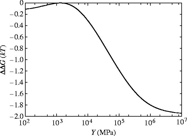
Allosteric free energy ΔΔG against the Young's modulus of each rod Y showing the effect of bending on the allosteric free energy for the model of parallel flexible rods free to slide and bend. The values of the parameters used are those given for dynein in appendix E.
Finite Y also means that ΔΔG saturates as a function of κ (figure 5) in contrast to the stiff result (equation (3.3), figure 3). For the parallel rigid rods the binding of the first ligand restricts the slide mode. The vibrations are already restricted when the second ligand binds leading to the observed divergence in ΔΔG (figure 3). However, for the flexible parallel rods though the first ligand binding restricts the slide mode the second ligand restricts the bend mode leading to the saturation behaviour for ΔΔG seen in figure 5. Figure 5 shows the effect of different values for the clamping potentials κ±1=k±1/k0, where we have set κ1=κ−1. k−1 is switched on by binding to microtubules and off by unbinding and k1 is switched on when there is no ATP-bound and switched off by ATP binding. Trivially for κ→0 the allosteric free energy ΔΔG→0. For large values of κ±1→∞ the small ΔΔG=−0.03kBT is approached for physical values of Y. The value of κ=100 is in this saturation region. Clearly to move beyond the poor allosteric properties of the simple parallel helices we need to account for the fully coiled-coil geometry.
Figure 5.
Allosteric free energy ΔΔG against clamping κ=k1/k0=k−1/k0 showing the effect of the clamping on the allosteric free energy for the model of flexible parallel rods free to slide and bend. The values of the parameters used are those given for dynein in appendix E.
5. Coiled geometry: slide and bend
5.1 Model
We now introduce the geometry of the two rods coiled round each other, as shown in figure 6. We consider the deformation to these paths under bending and relative slide ζ. We include the two perpendicular bending modes as curvature cx in the x direction and curvature cy in the y direction. These modes will be nearly but not perfectly degenerate due to the coiled geometry, so we include them explicitly. The paths become
| (5.1) |
Figure 6.
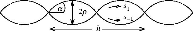
Diagram showing the geometry of two rods coiled round each other. α is the angle between the central axis and the path length along an individual rod. h is the helical pitch of the two rods coiled round each other. The distance between the centres of the rods is 2ρ.
We generalize the bending energy for a non-zero equilibrium curvature. We also include twist energy of each rod since there will be a twist induced by bend due to the coiled geometry. This gives us the internal elastic energy:
| (5.2) |
where τ is the geometrical torsion and w is the change in writhe (see appendix C for details). The factor (γ0−τ−w) is the local elastic energy-storing twist of the helices. For a rod of circular cross-section, radius ρ, we can write , where μ is the shear modulus. The factor of two is to account for the twisting of the two rods. We minimize the total Hamiltonian with respect to the writhe w to allow the system to choose the minimizing balance between slide and twist energies (see appendix C for details).
Substituting the calculated minimizing writhe w=wmin we write the Hamiltonian in the form , where K is a 3×3 elasticity matrix. We then calculate the allosteric free energy from equation (2.3).
Calculation details and results for the elements of K are given in appendix C.
5.2 Results
The dependence of ΔΔG for slide and bend modes with coiled geometry on the shear modulus μ and Young's modulus Y is given in figures 7 and 8, respectively. For rotationally stiff rods (μ→∞) the parallel rigid rods result (equation (3.3)) is approached. Similarly rods stiff to bending (Y→∞) approach this same result. The small curvature approximation of equation (5.1) breaks down for Y<103 MPa and μ<103 MPa (the persistence length becomes of order 10 nm<l0). So significance should not be read into the maxima at small μ and Y in figures 7 and 8.
Figure 7.
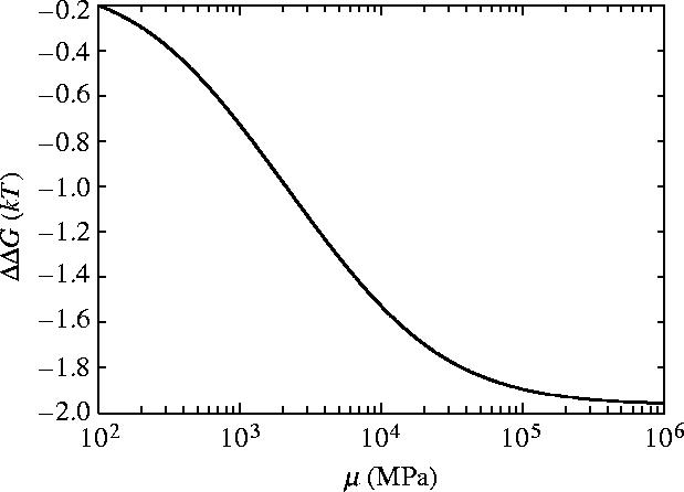
Allosteric free energy ΔΔG against the shear modulus of each rod μ showing the effect on the allosteric free energy for coiled geometry for slide and bend fluctuations.
Figure 8.
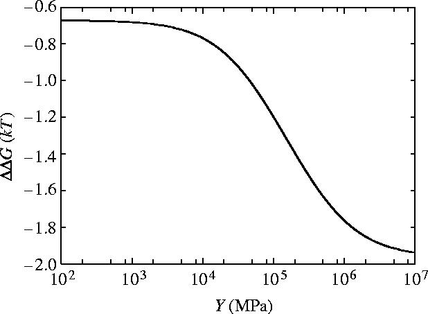
Allosteric free energy ΔΔG against the Young's modulus of each rod Y showing the effect on the allosteric free energy for coiled geometry for slide and bend fluctuations.
Figure 9 shows for coiled, flexible, inextensible rods with slide and bend fluctuations, using the parameters of appendix E, κ=100 is in the saturation region giving a free energy of
| (5.3) |
Figure 9.
Allosteric free energy ΔΔG against clamping κ=k1/k0=k−1/k0 showing the effect of clamping on the allosteric free energy for coiled geometry for slide and bend fluctuations.
From this it is clear that the coiled geometry partially restores the allosteric communication seen for rigid rods. This may be understood from the effective increase in the bending modulus achieved by coupling bending to twist of the helices by the coiled geometry.
6. Coiled geometry: slide, bend and twist
6.1 Model
We now also include a twisting mode. To introduce a fluctuation, t, in the twist, made up of some mechanical twist and some torsion, the writhe w is reduced by t due to conservation of linking number (see appendix D). We, therefore, repeat the calculation as in §5 but after we have minimized with respect to w we substitute in, not w=wmin, but w=wmin−t. Then we obtain a Hamiltonian of the form , where x=(ζ, cx, cy, t) and K is a 4×4 matrix We then calculate the allosteric free energy from equation (2.3).
Calculation details and results for the elements of K are given in appendix C.
6.2 Results
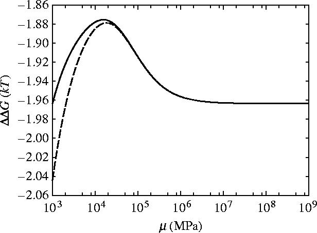
The dependence of ΔΔG for slide, bend and twist modes for coiled geometry on the shear modulus μ and Young's modulus Y is given in figures 10 and 11, respectively. For rotationally stiff rods (μ→∞) the parallel rigid rods result (equation (3.3)) is approached. For rods stiff to bending (Y→∞), however, the limit approached is this parallel rigid rods result plus an additional term which is non-zero for finite μ. Figure 12 shows that including this twist mode restores the non-saturation at high κ behaviour seen for the parallel rigid rods. This is due to the absence of slide twist coupling so twisting is allowed without sliding. The second ligand binding, therefore, does not restrict the twisting so has a much smaller effect than the first ligand binding thereby increasing the allosteric effect. Figure 10 shows the μ dependence of ΔΔG for three different values of κ=100, 500, 1000 showing the increased allosteric signal for increased values of κ. Figure 13 shows the μ dependence of ΔΔG for two different values of Y∼103, 104 MPa. The low μ behaviour is altered but the high μ saturation is unaffected by Y.
Figure 10.
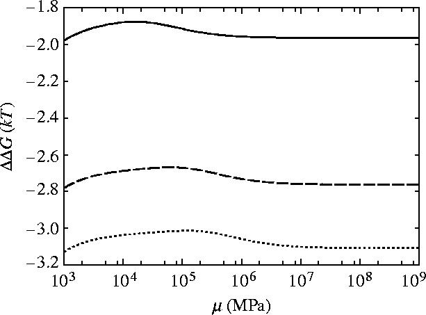
Allosteric free energy ΔΔG against the shear modulus of each rod μ showing the effect on the allosteric free energy for coiled geometry for slide, bend and twist fluctuations. Solid line is κ=100, dashed is κ=500 and dotted is κ=1000.
Figure 11.
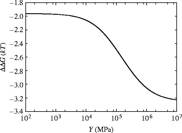
Allosteric free energy ΔΔG against Young's modulus Y showing the effect on the allosteric free energy for coiled geometry for slide, bend and twist fluctuations.
Figure 12.
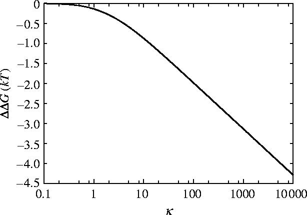
Allosteric free energy ΔΔG against clamping κ=k1/k0=k−1/k0 showing the effect of the clamping on the allosteric free energy for coiled geometry for slide, bend and twist fluctuations.
Figure 13.
Allosteric free energy ΔΔG against the shear modulus of each rod μ showing the effect on the allosteric free energy for coiled geometry for slide, bend and twist fluctuations. Solid line is Y∼103 MPa and dashed line is Y∼104 MPa.
For our physically relevant parameters (appendix E), including the twisting mode for coiled flexible rods restores the allosteric communication to the same as the rigid rods result to two significant figures (ΔΔG=−2.0kBT).
7. Discussion
We compare our calculated values for ΔΔG with experimental values for dynein affinity for microtubules. Kon et al. (2004) measure the kinetics of single headed cytoplasmic dynein binding microtubules in ATP. The wild type gives an association constant of K=3×10⁴ M−1. From ΔG=−RT ln K we obtain ΔG∼−10kBT. A mutated form which prevents ATP binding to the ‘P1’ site gives K=5×10⁶ M−1 (giving ΔG∼−15kBT). Assuming the wild type is the ATP-bound form and the mutant is the free form of dynein we obtain .
Earlier less direct work by Porter & Johnson (1983a,b) and Omoto & Johnson (1986) on a three-headed dynein under the simple assumption that the heads are independent lead to a similar but lower value than Kon et al. (2004) for the allosteric free energy. This value is consistent with the expectation that the successive binding of the three heads will actually be cooperative. Porter & Johnson (1983a) obtain a lower limit for the association constant, K∼107 M−1, from titrations of free three-headed tetrahymena dynein binding to bovine brain microtubules. This gives ΔG∼−16kBT and assuming the heads are independent we expect ΔG∼−5.4kBT for a single headed dynein. The same authors, Porter & Johnson (1983b) estimate the lower limit of the dissociation rate constant of the dynein with ATP-bound from the microtubules to be kd∼1000 s−1, from stopped flow light scattering methods. Omoto & Johnson (1986) give an association constant for ADP-bound dynein of ka=1.2×10⁴ M−1 s−1. Combining these values gives an equilibrium constant of . Since dynein binding to microtubules is unfavourable in this state, we assume this value corresponds to the affinity of one head. (Porter & Johnson (1983b) say that the kinetics they measure is not that expected for more than one ATP needed to dissociate the dynein.) This gives ΔG∼−2.5kBT. Combining these gives us a value of which is lower but of the same order as that obtained from Kon et al. (2004) of .
Comparing this with our calculations we note that if the ATP unclamps the end so that k−1=0 for the bound form compared to k−1/k0=κ−1 for the free form this corresponds to our value of ΔΔG∼−2.0kBT. This value uses an estimate of κ=100. If we use κ=1000 we obtain ΔΔG∼−3.1kBT. Our calculated values are sufficiently close to the experimental values, when a physical range of binding forces is assumed, for us to take this as quantitative evidence for our hypothesis: that dynein allostery is dominated by changes in the vibrational dynamics of the coiled-coil.
There exists static contributions to binding affinities unaffected by changes in the flexibility of the coiled-coil investigated by Mizuno et al. (2004) who measure the dissociation constant of the microtubule binding domain at the tip of the stalk (the dynein stalk head DSH) binding to microtubule giving an association constant of K=6×10⁵ M−1. This gives an indication of the static (mainly enthalpic) contribution ΔG∼−13kBT to the binding of each state. This value is consistent with the lower wild type ATP-bound association due to the large entropic cost of binding this flexible form.
Interestingly biochemical studies have also shown that there is allosteric communication in the other direction in dynein. Namely, as well as the presence of ATP determining microtubule release, after ATP hydrolysis the binding of microtubules accelerates the release of products ADP and Pi from dynein completing the ATPase cycle (Johnson 1985). This product release is thought to be coupled to the net movement of the motor (Porter & Johnson 1989). ADP release is thought to be the rate-limiting step in the dynein ATPase cycle (Holzbaur & Johnson 1989a). ADP release in the absence of microtubules has Kd=0.085 mM from Holzbaur & Johnson (1989a). ADP release from microtubule bound dynein has an equilibrium constant of Kd=0.37 mM (Holzbaur & Johnson 1989b). This gives us a value for the allosteric free energy of ADP release of . The microtubule bound dynein in our model has k1 on (clamped) making the decrease in vibrational free energy required for the k−1 clamped (free from ATP) state easier. Thus by tuning the values of κ1 and κ−1 our model can explain this back communication too.
To illustrate how our model can account for this ‘reverse allostery’ quantitatively, we can allow ADP to partially unclamp k−1 to a small value kADP rather than zero compared to the effect of ATP fully unclamping k−1=0. If we use κ1=κ−1=1000 we reproduce the allostery from the microtubules to the ADP (back communication) ΔΔG=−1.5kBT if κADP=kADP/k0=1.2.
To further test our hypothesis of this vibrational allosteric mechanism we compare calculations of the effective Young's modulus of the composite coiled-coil bending modes with that obtained from the observations of the changes in distribution of stalk tip positions from electron microscopy images of dynein-c by Burgess et al. (2003, 2004b). We calculate the effective Young's modulus of the composite coiled-coil for the bending mode in one plane from the element of our elasticity tensor, giving Yeff(ADP)=3.8×10¹⁰ J m−3 and Yeff(apo)=3.3×10¹¹ J m−3. The effective Young's modulus due to the bending mode in the plane perpendicular to this is given by giving Yeff(ADP)=3.0×10¹⁰ J m−3 and Yeff(apo)=1.6×10¹¹ J m−3. From the standard deviations of the angles (variance 〈Δθ2〉) quoted by Burgess et al. (2003), Lindemann & Hunt (2003) calculated effective spring constants for each state from the equipartition theorem keff=kBT/〈Δx2〉 where they took . Alternatively the distribution of curvatures of the stalk can be calculated and used to obtain an effective Young's modulus of the composite coiled-coil structure for each state giving Yeff(ADP)=2.7×10⁹ J m−3 and Yeff(apo)=8.9×10⁹ J m−3. These values are lower than our calculated values and show slightly less contrast between the different states. This is consistent with our parameterization of the Young's modulus for a single helix from the polyalanine calculation (appendix E) which may provide an upper bound for the less regular dynein helices, and also with the expectation that some of the apparent flexibility observed in both states is due to artefacts of the experimental method. Note the observed two dimensional images do show some information about the out of plane bending since scatter along the length of the stalk is seen in figure 1 which may be interpreted as out-of-plane bending.
We also note that the allosteric signal has a significant dependence on the number of turns i.e. the ratio of the length to the pitch (h=2π/γ0). As figure 14 shows, the phase of the coil controls the degree of coupling between twist and bend. This appears in the oscillatory nature of ΔΔG when plotted as a function of number of turns l0/h. Integral number of turns give the minimum allosteric effect with the maximum effect at half integral number of turns. This is since for integral number of turns the allosteric effect due to the bend-slide coupling cancels but is maximum for half turns. The parameters we have used (appendix E) in our calculations give the number of turns l0/h=1.2 which interestingly does not correspond to a maximum in |ΔΔG| (figure 14). It may turn out that the length of the stalk is different from previously assumed since the precise boundaries of the coiled-coil are hard to predict (Gibbons et al. 2005). Mutant forms of dynein might be used to explore this prediction by varying the length of the coiled-coil.
Figure 14.
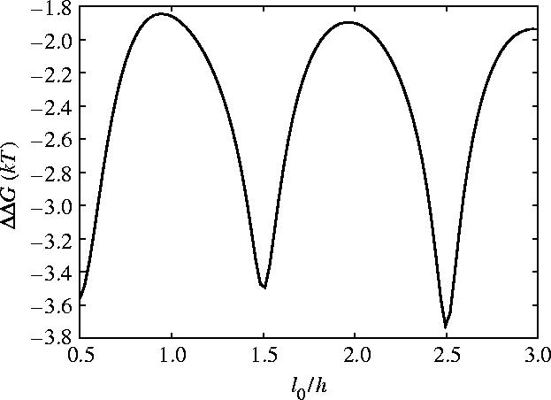
Allosteric free energy ΔΔG against the length in units of number of turns l0/h (where h is the pitch h=2π/γ0 which we fix) for coiled geometry for slide, bend and twist fluctuations.
The predictions of this work suggest a number of possible biochemical investigative experiments. The predicted allosteric free energy of ∼2kBT may be investigated by calorimetry which would show the entropic and enthalpic contributions. The predicted changes in effective Young's modulus of the dynein stalk could be investigated more accurately using cryo-electron microscopy which would avoid artefacts of absorbing to a surface. Such flexibility could also be studied by molecular dynamics simulations subject to the availability of suitable crystal structures. Mutations which alter the interactions between the helices in the coiled-coil are predicted to affect the allosteric communication due to their modulation of the slide mode. The dependence of the allosteric free energy on the number of turns suggests that coiled-coil mutants of varied lengths would show different allosteric free energies. In particular mutants adding 25% to the stalk length are predicted to substantially increase the allostery.
The slide mode may cause a rotation of the binding site at the tip of the stalk further reducing its affinity for microtubules. This would lead to an enthalpic contribution to ΔΔG emerging at this level of modelling.
In the present model the binding of ATP releases the clamp at the base of the stalk. From observing a model structure based on homologous AAA domains (Mocz & Gibbons 2001) it is conceivable that the binding of ATP could pull one helix away from the other reducing the interaction between them present in the absence of ATP. However the primary ATP binding site in the dynein head (the P1 site) is not the ATP binding site closest to the base of the stalk (Kon et al. 2004). The exact mechanism of the AAA ring is not known but it has been suggested that the AAA domains are cooperative causing ATP induced conformational and dynamics changes at the interface between the first two domains to propagate round the ring to the site of the base of the stalk (Vale 2000). The recent biochemical results on the role of the different ATP sites support the idea that the P2, P3 and P4 sites work cooperatively with the primary site (maybe with regulatory roles; Kon et al. 2004). A more sophisticated model would combine the allostery intrinsic to the coiled-coil developed here with a similar treatment of these allosteric effects within the AAA ring.
In conclusion, we find that a dynamic model of allosteric response is able to account for observed structural and thermodynamic data of the microtubule binding stalk of dynein. Furthermore, it suggests that significant allosteric free energy of ∼2kBT can be achieved quite generally by coiled-coils of 10–20 nm in length. Significantly, the coiled rather than simply parallel configuration of the helices proves essential for their allosteric function.
Acknowledgments
We thank Stan Burgess and Peter Knight for helpful discussion on dynein, Tanniemola Liverpool for discussions on the mathematical aspects and the EPSRC for finding.
Appendix A. Parallel rods: slide only
We start with a simple case by considering two inextensible, rigid rods, which lie parallel side by side and are not coiled round each other. The equilibrium paths of the upper rod, r1(s) and the lower rod, r−1(s), for two parallel rods are
| (A 1) |
Each rod is rigid (infinite bending Young's modulus), but we allow a finite potential between the two rods to account for resistance to sliding. The only fluctuation variable in this problem; is the relative slide between the rods which we call ζ. On sliding (equation (A 1)) deform to
| (A2) |
The general classical elastic internal energy of the two rods is
| (A 3) |
describing the energy due to relative sliding of the two rods. The integral is over s along the path length of the coiled-coil axis. The resistance to sliding kslide(s) is modelled by equation (2.6).
We calculate the slide parallel to the rods by taking the difference between the paths for each rod. This gives us Δs=Δrz(s)=ζ.
We substitute equation (2.6) and Δs=ζ into equation (A 3) and integrate over the path length −l0/2<s<l0/2. After performing the integration we obtain
The free energy is given by equation (2.2), where in this case of just one degree of freedom ,
We calculate the allosteric free energy from equation (2.3) and using the liganded conditions (equation (2.5)),
| (A4) |
Appendix B. Parallel rods: slide and bend
We impose a relative slide ζ of the two rods parallel to the central axis by introducing the additional term ±ζ/2 in the z direction. We now also impose a bend of curvature c in the positive x direction. This adds an additional term of cs2/2, in the x direction. Bending also induces a relative slide (−2ρcs) between the rods. We include this slide induced by bend by adding ∓ρcs to the z component, giving
| (B 1) |
to linear order in the fluctuation variables c and ζ. In general there is also a bending mode in the y direction However in this case, since it is not coupled to the sliding, it ends up not affecting ΔG so we omit it in this simple case. Bending in the y direction is not coupled to the sliding since the two rods are at the same position in y (one is above the other in x).
The classical elastic internal energy of the rods will be made up of the energy due to bending of each rod and the energy of relative slide between the rods. We combine these energies to give
| (B 2) |
where Y is the Young's modulus of the rod and I is the moment of inertia about the y-axis which for circular cross-section radius ρ is . The factor of two accounts for the bending energy of the two rods. kslide(s) is given by equation (2.6). We take the origin of bending at the centre of mass of the rod, so the rod path runs −l0/2<s<l0/2.
We can calculate the curvature from the deformed paths (equation (B 1)). We calculate the relative slide of the rods by taking the difference between the path lengths for each rod, . We thus obtain
| (B3) |
| (B 4) |
to linear order in c and ζ. The slide Δs is made up of the slide mode itself ζ and the slide between the rods induced by bend −2ρcs. This bend-slide term accounts for the coupling between bending and sliding motion.
We substitute equations (2.6), (B 3) and (B 4) into equation (B 2) and integrate over the path length −l0/2<s<l0/2.
We can write this Hamiltonian as where x=(ζ, c) and
We then obtain the free energy from equation (2.2)
Therefore, the allosteric free energy is given by
Appendix C. Coiled geometry: slide and bend
We now use helical geometry of two rods coiled round each other. In order to work out the position vector of the individual rods r±1 in the new geometry it is helpful to refer to figures 6 and 15. The x, y and z components of the position vector of an individual rod r±1(s) can be calculated from figure 15a,b, where s is the path length along the central axis of the coiled-coil (the neutral line):
| (C1) |
where γ=2π/h and h is the helical pitch. The subscripts 0 refer to these being the equilibrium paths with zero bend fluctuation. Setting γ=0 reproduces the paths for the parallel geometry in §4.
Figure 15.
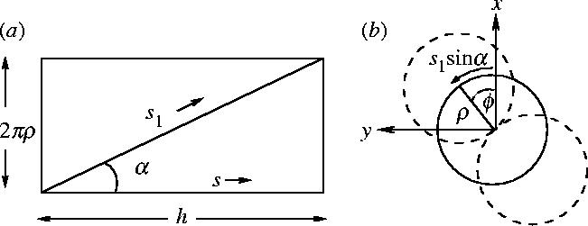
(a) Diagram showing the coil in figure 6 unrolled. ρ is the radius of the circle that the centre of one rod travels in the coil structure. Therefore the circumference is 2πρ which makes the vertical side. The horizontal side is in the direction of the arc length of the centre of the coil s ( if there is no bend) and the pitch h. The individual rod arc length, s1 is along the diagonal in the unrolled geometry. (b) Diagram showing the coil of the two rods in figure 6 end on. Again ρ is the radius the centre of one rod travels. The arc length s1 sin α marked is the component of individual rod arc length s1 along the vertical side of the unrolled geometry in (b). ϕ is the global twist angle defined as the angle between the line joining the centres of the two rods and the x-axis.
We consider the deformation to these paths under bending and relative slide ζ. Due to the helical geometry the relative slide induced by bend is now (∓ρc cos γ0s)s. We include the two perpendicular bending modes as curvature cx in the x direction and curvature cy in the y direction. These modes will be nearly but not perfectly degenerate due to the coiled geometry so we include them explicitly. Therefore we obtain . Including the relative slide ζ (ζ cos α along z) gives the z component in the deformed path (equation (C 2)):
| (C 2) |
We generalize the bending energy for a non-zero equilibrium curvature and include twist energy since there will be a twist induced by bend due to the coiled geometry. This gives us the internal elastic energy:
| (C 3) |
where τ is the geometrical torsion and w is the change in writhe (see equations (C 4) and (C 5)). For a rod of circular cross-section, radius ρ, where μ is the modulus of rigidity. The factor of two is to account for the twisting of the two rods. To obtain the mechanical twist energy we calculate , where α is the rate of change of angle of a groove marked along an untwisted rod (helicity). Part of this change in angle is due to the geometrical torsion of the geometry and part from the mechanical twist of the rod. The part due to the mechanical twist (α−τ) costs energy. The torsion can be calculated from the geometry of the paths. For two rods which can slide relative to each other α is made up of the twist of the individual rod and relative slide perpendicular to the neutral axis. We allow the system freedom to choose how much to twist and how much to slide depending on the relative energy costs of each. This balance is governed by the conservation of linking number (theorem White 1969), Lk which is made up of the writhe Wr and the twist Tw:
| (C 4) |
The linking number is conserved (ΔLk=0) for a particular topology. The microtubule binding tip is a closed loop forming the antiparallel coiled-coil and the other end is attached to the dynein head which is large in comparison with the stalk and we therefore argue will preserve the coiled-coil topology due to its large rotational diffusion constant. We therefore take ΔLk=0 for the fluctuations we consider for the dynein coiled-coil. This conserved Lk leads to the calculation
| (C 5) |
where w is the change in writhe and α−α0 is the change in helicity. α0=γ0 therefore α=γ0−w. We allow the system to choose the optimal writhe twist balance by minimizing the total elastic energy with respect to w (equation (C 13)).
To obtain the curvature of the deformed and equilibrium paths we calculate
| (C 6) |
where we have taken the approximation simplifying the z component of equation (C 2). We then obtain the curvature:
| (C 7) |
We have expanded to linear order in cx and cy only, so that the Hamiltonian is in the harmonic approximation. The curvature induced by bending the coiled-coil is dependent on cos γ0s. This means at points where rx is maximum the bending decreases the curvature. However at points where rx is minimum the bend induces an increase in curvature at this point, as expected intuitively.
The slide parallel to the neutral axis is given by calculating Δs=Δrz/cos α, where . The slide perpendicular to the neutral axis is given by the writhe angle multiplied by the radius giving ; therefore,
| (C 8) |
The torsion can be calculated from
| (C9) |
We use equation (C 6) to obtain
| (C10) |
We take up to quadratic order only, obtaining
| (C11) |
| (C 12) |
We substitute the curvature (equation (C 7)), slide (equation (C 8)) and twist (equation (C 12)) into equation (C 3), to obtain the elastic energy to quadratic order. We then minimize this with respect to w allowing the system to choose its optimal writhe, twist balance giving
| (C 13) |
Substituting this value back into the Hamiltonian gives , where x=(ζ, cx, cy) and the components of K are given as
| (C14) |
where
| (C 15) |
We then obtain the free energy and allosteric free energy from equations (2.2) and (2.3)
Appendix D. Coiled geometry: slide, bend and twist
We now also include a twisting mode. To introduce a fluctuation, t, in the twist, what we mean is a fluctuation in the helicity, α, which is made up of some mechanical twist and some torsion and is governed by the conservation of linking number.
shows us that the writhe w must decrease by t. We, therefore, repeat the calculation as in appendix C but after we have minimized with respect to w we substitute in, not w=wmin but, w=wmin−t. Then we obtain a Hamiltonian of the form , where x=(ζ, cx, cy, t) and K is a 4×4 matrix with components
| (D1) |
where a1–a9 are given by equations (C 15) and
| (D2) |
We then obtain the free energy and allosteric free energy from equations (2.2) and (2.3).
Appendix E. Parameterization
The geometry of the dynein is known from electron microscopy imaging by Burgess et al. (2003, 2004a) giving the values in equations (E 1) and (E 2). We take the pitch to be 13 nm from Offer & Sessions (1995) giving the value in equation (E 3).
The bulk elasticity Young's modulus (the ratio of stress to strain for deformation along a single axis) has typical values of Y∼109 J m−3 for non-crystalline soft matter (Boal 2002). The persistence length of a rod of isotropic elasticity and transverse moment of inertia I is lp=YI/kBT. For long alkanes lp∼0.5 nm, F-actin lp∼10 μm, and microtubules lp∼1–6 mm (Boal 2002). Therefore Y∼109 J m−3 for most filaments (Boal 2002). We expect lp and Y of an alpha helix to be less than that for microtubules and actin but more than long alkanes.
We investigated an estimate of the persistence length of an alpha helix by considering the normal modes of a simple polyalanine alpha helix with 100 residues (since the coil–coil helices in dynein are about this long). We used the Nmode program in AMBER (Case et al. 2004). We used a distance dependent dielectric constant to model solvent implicitly. We set the mass matrix to the identity to calculate the non-mass weighted eigenvalues. This gave a frequency of ν′=1.56 amu1/2 cm−1 for the lowest mode (bend). The eigenvalue is, therefore, , which is equal to the effective spring constant for the mode ksp=2.3×10⁻⁵ J m−2. Reading off the amplitude of displacement of the end atom from the eigenvector calculated by Nmode we find δe=0.066 Å, and the displacement of the middle atom is δm=0.037 Å. From geometry (see figure 16) the radius of maximally excited curvature . We use this to find R=2.9 μm. Using , where |x|2=1 Å2 (the unit eigenvector of the force constant matrix in AMBER has units of Å) we obtain Y=2.5×10⁹ J m−3, in line with our expectations. This corresponds to persistence length . A regular polyalanine helix may provide an upper bound to Y for the less regular dynein helix.
Figure 16.
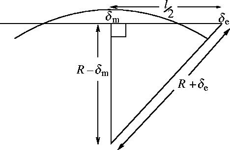
Diagram to show geometry of the lowest normal mode (bend) used to calculate the Young's modulus Y of an alpha helix from the NMA using AMBER.
We expect the shear modulus μ to be the same order of magnitude as Y. We used the polyalanine normal mode analysis to estimate μ from the lowest twisting mode. The non-mass normalized constant gave us a frequency of ν′=6.5 cm−1 amu1/2. The end atom is found to be displaced by δ=0.066 Å for the lowest twisting mode. From geometrical considerations (see figure 17) . From we obtain .
Figure 17.
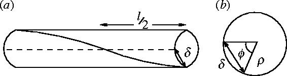
Diagram to show geometry of the lowest twist normal mode used to calculate the shear modulus μ of an alpha helix from the NMA using AMBER (a) The lowest twist mode of rod of length l. The straight groove (dashed line) becomes twisted (solid line). (b) Looking at the rod end on (radius ρ). The twist is described by the angle ϕ and the displacement of end atom is δ.
The adhesive resistance to mutual sliding k0 will be due to the hydrophobic effect which holds the two alpha helices together in a coiled-coil. To estimate the magnitude of this we take the surface tension of an oil water interface giving typically T=5×10⁻² J m−2 (Boal 2002). The change in energy due to sliding Δs is then , where w is the width of the hydrophobic stripe which we take to be of the order of Δs so k0∼0.1 J m−2 (equation (E 6)).
To estimate the order of magnitude of κ±1 we calculate the effect of introducing charges which cause the clamping by the Coulomb interaction energy q2/4πϵ0r, where q is the charge. We take the separation between charges r to be ρ. We equate the change in coulomb interaction energy to the energy of sliding Δs to obtain
Koonce & Tikhonenko (2000) investigate the effect of alanine substitutions of conserved charge residues in the microtubule binding region of dynein. They find there are four charged residues, which affect the ATP-stimulated release of dynein from microtubules. It may be that these charges are the ones which form our k1. We, therefore, take q=4e. This gives us an estimate of κ1=k1/k0=590. As a conservative estimate we take κ±1=100 so κ±1 is two orders of magnitude larger than k0.
We write here, for convenience, all the parameters used:
| (E 1) |
| (E 2) |
| (E 3) |
| (E4) |
| (E5) |
| (E 6) |
| (E7) |
Footnotes
One contribution of 8 to a themed supplement ‘Statistical mechanics of molecular and cellular biological systems’.
References
- Boal D. Cambridge University Press; Cambridge: 2002. Mechanics of the cell. [Google Scholar]
- Burgess S.A, Walker M.L, Sakakibara H, Knight P.J, Oiwa K. dynein structure and power stroke. Nature. 2003;421:715–718. doi: 10.1038/nature01377. doi:10.1038/nature01377 [DOI] [PubMed] [Google Scholar]
- Burgess S, Walker M, Sakakibara H, Oiwa K, Knight P. The structure of dynein-c by negative stain electron microscopy. J. Struct. Biol. 2004a;146:205–216. doi: 10.1016/j.jsb.2003.10.005. doi:10.1016/j.jsb.2003.10.005 [DOI] [PubMed] [Google Scholar]
- Burgess S.A, Walker M.L, Thirumurugan K, Trinick J, Knight P.J. Use of negative stain and single-particle image processing to explore dynamic properties of flexible macromolecules. J. Struct. Biol. 2004b;147:247–258. doi: 10.1016/j.jsb.2004.04.004. doi:10.1016/j.jsb.2004.04.004 [DOI] [PubMed] [Google Scholar]
- Case D, et al. University of California; San Francisco: 2004. AMBER 8. [Google Scholar]
- Cooper A, Dryden D.T.F. Allostery without conformational change—a plausible model. Eur. Biophys. J. Biophys. Lett. 1984;11:103–109. doi: 10.1007/BF00276625. doi:10.1007/BF00276625 [DOI] [PubMed] [Google Scholar]
- Gee M, Vallee R. The role of the dynein stalk in cytoplasmic and flagellar motility. Eur. Biophys. J. Biophys. Lett. 1998;27:466–473. doi: 10.1007/s002490050157. doi:10.1007/s002490050157 [DOI] [PubMed] [Google Scholar]
- Gee M, Heuser J, Vallee R. An extended microtubule-binding structure within the dynein motor domain. Nature. 1997;390:636–639. doi: 10.1038/37663. doi:10.1038/37663 [DOI] [PubMed] [Google Scholar]
- Gibbons I, Garbarino J.E, Tan C.E, Reck-Peterson S.L, Vale R.D, Carter A.P. The affinity of the dynein microtubule-binding domain is modulated by the conformation of its coiled-coil stalk. J. Biol. Chem. 2005;280:23 960–23 965. doi: 10.1074/jbc.M501636200. doi:10.1074/jbc.M501636200 [DOI] [PMC free article] [PubMed] [Google Scholar]
- Hawkins R.J, McLeish T.C.B. Coarse-grained model of entropic allostery. Phys. Rev. Lett. 2004;93:098104. doi: 10.1103/PhysRevLett.93.098104. doi:10.1103/PhysRevLett.93.098104 [DOI] [PubMed] [Google Scholar]
- Holzbaur E, Johnson K. ADP release is rate limiting in steady-state turnover by the dynein adenosinetriphosphatase. Biochemistry. 1989a;28:5577–5585. doi: 10.1021/bi00439a036. doi:10.1021/bi00439a036 [DOI] [PubMed] [Google Scholar]
- Holzbaur E, Johnson K. Microtubules accelerate ADP release by dynein. Biochemistry. 1989b;28:7010–7016. doi: 10.1021/bi00443a034. doi:10.1021/bi00443a034 [DOI] [PubMed] [Google Scholar]
- Johnson K.A. Pathway of the microtubule-dynein ATPase and the structure of dynein: a comparison with actomyosin. Annu. Rev. Biophys. Biophys. Chem. 1985;14:161–188. doi: 10.1146/annurev.bb.14.060185.001113. doi:10.1146/annurev.bb.14.060185.001113 [DOI] [PubMed] [Google Scholar]
- Jülicher F. Supercoiling transitions of closed DNA. Phys. Rev. E. 1994;49:2429–2435. doi: 10.1103/physreve.49.2429. doi:10.1103/PhysRevE.49.2429 [DOI] [PubMed] [Google Scholar]
- Jusuf S, Loll P.J, Axelsen P.H. Configurational entropy and cooperativity between ligand binding and dimerization in glycopeptide antibiotics. J. Am. Chem. Soc. 2003;125:3988–3994. doi: 10.1021/ja027780r. doi:10.1021/ja027780r [DOI] [PubMed] [Google Scholar]
- Kern D, Zuiderweg E.R.P. The role of dynamics in allosteric regulation. Curr. Opin. Struct. Biol. 2003;13:748–757. doi: 10.1016/j.sbi.2003.10.008. doi:10.1016/j.sbi.2003.10.008 [DOI] [PubMed] [Google Scholar]
- Kon T, Nishiura M, Ohkura R, Toyoshima Y.Y, Sutoh K. Distinct functions of nucleotide-binding/hydrolysis sites in the four AAA modules of cytoplasmic dynein. Biochemistry. 2004;43:11 266–11 274. doi: 10.1021/bi048985a. doi:10.1021/bi048985a [DOI] [PubMed] [Google Scholar]
- Koonce M, Tikhonenko I. Functional elements within the dynein microtubule-binding domain. Mol. Biol. Cell. 2000;11:523–529. doi: 10.1091/mbc.11.2.523. [DOI] [PMC free article] [PubMed] [Google Scholar]
- Lindemann C.B, Hunt A.J. Does axonemal dynein push, pull, or oscillate? Cell Motil. Cytoskeleton. 2003;56:237–244. doi: 10.1002/cm.10148. doi:10.1002/cm.10148 [DOI] [PubMed] [Google Scholar]
- Marko J.F. DNA under high tension: overstretching, undertwisting, and relaxation dynamics. Phys. Rev. E. 1998;57:2134–2149. doi:10.1103/PhysRevE.57.2134 [Google Scholar]
- Mizuno N, Toba S, Edamatsu M, Watai-Nishii J, Hirokawa N, Toyoshima Y.Y, Kikkawa M. dynein and kinesin share an overlapping microtubule-binding site. EMBO J. 2004;23:2459–2467. doi: 10.1038/sj.emboj.7600240. doi:10.1038/sj.emboj.7600240 [DOI] [PMC free article] [PubMed] [Google Scholar]
- Mocz G, Gibbons I. Model for the motor component of dynein heavy chain based on homology to the AAA family of oligomeric ATPases. Structure (Camb.) 2001;9:93–103. doi: 10.1016/s0969-2126(00)00557-8. doi:10.1016/S0969-2126(00)00557-8 [DOI] [PubMed] [Google Scholar]
- Moroz J.D, Nelson P. Entropic elasticity of twist-storing polymers. Macromolecules. 1998;31:6333–6347. doi:10.1021/ma971804a [Google Scholar]
- Offer G, Sessions R. Computer modelling of the alpha-helical coiled coil: packing of side-chains in the inner core. J. Mol. Biol. 1995;249:967–987. doi: 10.1006/jmbi.1995.0352. doi:10.1006/jmbi.1995.0352 [DOI] [PubMed] [Google Scholar]
- Omoto C, Johnson K. Activation of the dynein adenosinetriphosphatase by microtubules. Biochemistry. 1986;25:419–427. doi: 10.1021/bi00350a022. doi:10.1021/bi00350a022 [DOI] [PubMed] [Google Scholar]
- Porter M, Johnson K. Characterization of the ATP-sensitive binding of Tetrahymena 30 S dynein to bovine brain microtubules. J. Biol. Chem. 1983a;258:6575–6581. [PubMed] [Google Scholar]
- Porter M, Johnson K. Transient state kinetic analysis of the ATP-induced dissociation of the dynein–microtubule complex. J. Biol. Chem. 1983b;258:6582–6587. [PubMed] [Google Scholar]
- Porter M, Johnson K. dynein structure and function. Annu. Rev. Cell Biol. 1989;5:119–151. doi: 10.1146/annurev.cb.05.110189.001003. doi:10.1146/annurev.cb.05.110189.001003 [DOI] [PubMed] [Google Scholar]
- Rossetto V, Maggs A.C. Writhing geometry of open DNA. J. Chem. Phys. 2003;118:9864–9874. doi:10.1063/1.1569905 [Google Scholar]
- Vale R. AAA proteins. Lords of the ring. J. Cell Biol. 2000;150:F13–F19. doi: 10.1083/jcb.150.1.f13. doi:10.1083/jcb.150.1.F13 [DOI] [PMC free article] [PubMed] [Google Scholar]
- White J.H. Self-linking and the gauss integral in higher dimensions. Am. J. Math. 1969;91:693–728. [Google Scholar]