

Abstract
Constitutive relations are fundamental to the solution of problems in continuum mechanics, and are required in the study of, for example, mechanically dominated clinical interventions involving soft biological tissues. Structural continuum constitutive models of arterial layers integrate information about the tissue morphology and therefore allow investigation of the interrelation between structure and function in response to mechanical loading. Collagen fibres are key ingredients in the structure of arteries. In the media (the middle layer of the artery wall) they are arranged in two helically distributed families with a small pitch and very little dispersion in their orientation (i.e. they are aligned quite close to the circumferential direction). By contrast, in the adventitial and intimal layers, the orientation of the collagen fibres is dispersed, as shown by polarized light microscopy of stained arterial tissue. As a result, continuum models that do not account for the dispersion are not able to capture accurately the stress–strain response of these layers. The purpose of this paper, therefore, is to develop a structural continuum framework that is able to represent the dispersion of the collagen fibre orientation. This then allows the development of a new hyperelastic free-energy function that is particularly suited for representing the anisotropic elastic properties of adventitial and intimal layers of arterial walls, and is a generalization of the fibre-reinforced structural model introduced by Holzapfel & Gasser (Holzapfel & Gasser 2001 Comput. Meth. Appl. Mech. Eng. 190, 4379–4403) and Holzapfel et al. (Holzapfel et al. 2000 J. Elast. 61, 1–48). The model incorporates an additional scalar structure parameter that characterizes the dispersed collagen orientation. An efficient finite element implementation of the model is then presented and numerical examples show that the dispersion of the orientation of collagen fibres in the adventitia of human iliac arteries has a significant effect on their mechanical response.
Keywords: anisotropy, constitutive modelling, arterial layers, arterial wall mechanics, fibre distribution, collagen fibres
1. Introduction
In a soft biological tissue, as for every solid with a microstructure, there is a correlation between its internal structure and its macroscopic mechanical properties. Continuum-based constitutive relations describe the gross behaviour that results from the internal constitution, and their development for soft biological tissues has been an area of active research for several decades. Constitutive relations are of fundamental importance for the solution of problems in continuum mechanics since without them, from the mathematical point of view, the system of equations that governs the mechanics is not solvable.
Extensive experience reveals that many clinical interventions involving soft biological tissues can be studied within the context of continuum mechanics, as the example of arterial clamping discussed by Gasser et al. (2002) illustrates. The solution of boundary-value problems can help in understanding mechanically dominated clinical treatments, such as balloon angioplasty (Holzapfel et al. 2002b), and therefore, in principle, contribute to their improvement. Such solutions can also help to understand better arterial failure mechanisms, such as in dissection (Roach & Song 1994) and rupture of aneurysms (Humphrey & Canham 2000), and they have the potential to assist in the development of tissue engineering (Butler et al. 2000). For a detailed review of the potential of continuum mechanics in understanding the mechanics of clinical applications, the reader is referred to the recent review article by Humphrey (2003), and for an overview of the biomechanics of soft tissues see the volumes edited by Holzapfel & Ogden (2003, in press).
Constitutive equations are also critical for obtaining a deeper insight into the physiological and the pathological load carrying mechanisms in soft biological tissues. In particular, structural constitutive models, which are the focus of this paper, are best suited for the study of the structural and functional interrelation in response to changes in the mechanical loading. Such models attempt to integrate information on tissue composition and structure, and they therefore include more information about the tissue than purely phenomenological models. Moreover, a structural approach must account for the internal load carrying mechanisms of the individual constituents of the tissue, and this then increases its predictive capability compared with a phenomenological approach.
Soft biological tissue consists primarily of various types of cells, an extracellular matrix, and abundant water. Numerous cell types sense and convert mechanical stimuli (signals) into bioelectrical and biochemical signals and activate the tissue's homeostatic tendency to adapt in response to changes in its mechanical environment. Individual cells probably respond to conformational changes of molecules (although this is not clear), but macroscopic continuum quantities such as stress and strain will nevertheless continue to be convenient metrics for relating the adaptation of the tissue to a particular mechanical stimulus (Humphrey 2001). Hence, realistic constitutive modelling of soft biological tissues is a prerequisite for quantifying changes in their structure and function in response to altered mechanical stimulus.
Insight into the structural organization of the complex three-dimensional elastin, collagen and smooth muscle arrangement within the arterial wall has been obtained by application of polarized light microscopy to stained arterial tissue, as in the extensive investigations by Canham and co-workers (Canham et al. 1989; Finlay et al. 1995, 1998). These studies illustrate clearly the dispersion of the structural orientation in the adventitial and intimal layers, which contrasts with the consistently close to circumferential organization in the media. Based on this histological evidence, the primarily goal of the present work is to introduce a hyperelastic free-energy function that is motivated by the anisotropic structural arrangement of arterial layers and, in particular, allows the dispersion of the collagen fibre orientation to be incorporated. A crucial issue is therefore the development of a framework that is particularly suitable for characterizing the dispersion of the collagen fibre orientation in a continuum sense.
Structurally based constitutive models have been developed for a variety of intact tissues and tissue components. Perhaps the most complete approach has been presented by Lanir (1983). In arterial wall mechanics fibre-reinforced models, where the collagen fibres are assumed to be embedded in an isotropic groundmatrix1, have become an attractive mechanical approximation to the tissue composition (Holzapfel et al. 2000). The histology of arterial tissue shows that collagen fibres are crimped in the unstressed tissue (Lanir 1983), and this fact motivated the introduction of statistical distribution functions in order to capture the waviness of the collagen fibres (Wuyts et al. 1995; Zulliger et al. 2004). It is worth noting that the idea of crimped collagen fibres in the unstressed arterial tissue is about half a century old and dates back to the work of Roach & Burton (1957).
In the anisotropic elastic energy function proposed by Holzapfel et al. (2000) and Holzapfel & Gasser (2001) it was assumed that the collagen fibres are perfectly aligned. This model works well for the media, but it does not reflect the behaviour of the intima and adventitia, for which there is significant fibre dispersion. In the formulation introduced here, therefore, we include a measure of the dispersion of collagen orientation, thereby generalizing the model of Holzapfel et al. (2000) and Holzapfel & Gasser (2001). In particular, a scalar structure parameter representing the diversity of the collagen arrangement enters the hyperelastic formulation. This generalization has significant consequences for the mechanical response of the model. Note that the traditional definition of a free-energy function, as is adopted here, requires the use of a stress-free reference configuration. Generally, however, a compatible stress-free configuration of the arterial wall does not exist and, in order to incorporate the effect of residual stress, several approaches are possible. For example, it can be assumed that such a configuration exists globally (at least as an approximation), as is done in the ‘opened-up geometry’, which is achieved experimentally by a radial cut of a cylindrical arterial specimen; see, for example, Fung (1993) and Holzapfel et al. (2000). An alternative is to adopt an incompatible ‘virtual’ stress-free configuration; see, for example, Lubarda & Hoger (2002) and references therein, and the recent contribution by Stålhand (2005).
In §2, an overview of the arterial wall is provided from the biomechanical perspective. This includes discussion of arterial histology and of the typical mechanical properties of the layers. The structural constitutive formulations that are available in the literature are then reviewed. In §3, the underlying continuum mechanical framework is summarized, and particular emphasis is given to the continuum representation of dispersed fibre orientations. Section 4 focuses on the introduction of a new hyperelastic model for arterial layers. Key issues are the representation of a transversely isotropic distribution of the orientation of collagen fibres and the associated particularization of the anisotropic free-energy function for arterial layers, as discussed in §§4.1 and 4.2, respectively. In §4.3 the required expressions for an efficient finite element implementation of the proposed model are summarized. Finally, the model is particularized on the basis of experimental data from the adventitia of human iliac arteries, and two numerical examples are used, in §5, to demonstrate the efficacy of the proposed model. These are inflation of a thin-walled tube and uniaxial tension of rectangular specimens from the circumferential and axial directions of a tube.
2. The arterial wall from a biomechanical point of view
This section is included in order to summarize the essential histological and biomechanical features of the arterial wall and provides basic information for its constitutive modelling. It is axiomatic in continuum mechanics that the properties of a material result from its internal constitution, which includes the distribution, orientation, and interconnections of its constituents. Hence, we start this section with a brief review of (human) arterial histology in §2.1, which is addressed particularly to readers without a background in biology or physiology and complements the discussion provided by Holzapfel et al. (2000). The characteristic mechanical properties of the arterial wall are then summarized in §2.2, while §2.3 contains a review of constitutive models for arteries with particular emphasis on structurally-based formulations.
For a more detailed exposition of the different interrelated arterial components and the overall functioning of the blood vessel see, for example, the reviews by Rhodin (1980) and Silver et al. (1989). Qualitative and quantitative details of the three-dimensional structural organization of arteries are discussed in Canham et al. (1989) and Finlay et al. (1995).
2.1 Arterial histology
Arteries can be roughly subdivided into two types: elastic and muscular, although there are arteries that are intermediate between both types. Elastic arteries have relatively large diameters and are located close to the heart, while muscular arteries are located at the periphery (except in the case of coronary arteries). We focus attention on the histology of arterial walls composed of three distinct layers, the intima, the media and the adventitia. Moreover, we discuss the constituents of arterial walls from the mechanical perspective and introduce a histomechanical idealization of an elastic artery with non-atherosclerotic intimal thickening, as illustrated schematically in figure 1. Note that this is somewhat different from the corresponding figure shown in Holzapfel et al. (2000).
Figure 1.

Histomechanical idealization of a healthy elastic artery with non-atherosclerotic intimal thickening. It is composed of three layers: intima (I), media (M), adventitia (A). I is the innermost layer consisting of a single layer of endothelial cells, a thin basal membrane and a subendothelial layer. The subendothelial layer is comprised mainly of thinly dispersed smooth muscle cells and bundles of collagen fibrils. M is composed of smooth muscle cells, a network of elastic and collagen fibrils and elastic laminae which separate M into a number of transversely isotropic fibre-reinforced units. A is the outermost layer surrounded by loose connective tissue. The primary constituents of A are thick bundles of collagen fibrils arranged in helical structures.
2.1.1 Intima
The intima is the innermost layer of the artery. It comprises primarily a single layer of endothelial cells lining the arterial wall, resting on a thin basal membrane, and a subendothelial layer of varying thickness (depending on topography, age and disease). The subendothelial layer, as considered in the present work, develops due to diffuse (non-atherosclerotic) intimal thickening, a homeostatic reaction of the intima that tends to restore baseline levels of the stress (Glagov et al. 1993), and it is present even in the very early stages of life (Hartman 1977).
While the endothelial layer does not contribute significantly to the load-carrying capability of the wall, the subendothelial layer can do so. The thickness of the subendothelial layer ranges from almost non-existent up to being geometrically dominant; see, for example, the investigations on coronary arteries in Hartman (1977), Canham et al. (1989) and Holzapfel et al. (in press). The subendothelial layer of coronary arteries studied by Canham et al. (1989) was dominated by collagen with thinly dispersed smooth muscle cells (the predominant cell type in the subendothelial layer (Rhodin 1980)) throughout the layer. Its architecture seems to be associated with intimal fibromuscular hypertrophy, where compact fibrocellular layers are formed, resembling the media (Glagov et al. 1993). The high content of collagen, primarily of types I and III (von der Mark 1981; Shekhonin et al. 1985), suggests its mechanical dominance, which has recently been confirmed for coronary arteries by Holzapfel et al. (in press). For a recent review of vascular collagen in general the reader is referred to Plenz et al. (2003).
The orientation of the collagen fibres in the subendothelial layer is not uniform through the thickness of the layer. There is a distinctive organization of multilayered fabric of collagen in the subendothelium, which structurally separates the subendothelial layer. For example, five separate layers with differently aligned families in coronary arteries (Canham et al. 1989) and three layers in brain arteries are found (Finlay et al. 1995). Moreover, the distinct families of collagen fibres in the subendothelium are characterized by large deviations of individual collagen fibres from the mean orientations. There is also elastin present in the subendothelium; it is arranged in a three-dimensional network of elastic fibres (Rhodin 1980).
For the sake of completeness it should be noted that the intima thickens and stiffens locally with atherosclerosis, which involves deposition of fatty substances, calcium, collagen fibres, cellular waste products and fibrin (Hartman 1977; Stary 2003). These pathological changes are associated with significant alterations in geometry and in the mechanical properties of the arterial wall, to the extent that the mechanical contribution of the diseased intima may dominate that of the other layers. In particular, the distribution of collagen in the different types of tissue changes significantly; see Shekhonin et al. (1985) for a detailed investigation of collagen in the regionally thickened intima, lipid streaks, fibrous plaques and the fibrous cap.
2.1.2 Media
The media is the middle layer of the artery and consists of a complex three-dimensional network of smooth muscle cells, elastin and bundles of collagen fibrils (Clark & Glagov 1979). According to Rhodin (1980) the fenestrated elastic laminae separate the media into a varying number of well-defined concentrically fibre-reinforced medial layers. The alternating layers result from the repeating of discrete (basic) structural and functional units called musculoelastic fascicles (Clark & Glagov 1979). The thickness of these units is independent of the radial location in the wall and the number of units increases with increasing medial thickness. The elastin pattern loses its organization toward the periphery (Roach & Song 1994) so that the laminated architecture of the media is hardly present in muscular arteries.
The media is separated from the intima and adventitia by the so-called internal elastic lamina and external elastic lamina, respectively (the latter is absent in cerebral blood vessels). In muscular arteries these laminae appear as prominent structures, whereas in elastic arteries they are hardly distinguishable from the regular elastic laminae. The elastin, bundles of collagen fibres and smooth muscle cells and their interconnections together constitute a continuous fibrous helix (Schultze-Jena 1939; Staubesand 1959). The helix has a small pitch so that within the media it is almost circumferentially oriented. Moreover, polarized light microscopy (Canham et al. 1989; Finlay et al. 1995) has shown that collagen, about 30% of type I and 70% of type III (von der Mark 1981; Shekhonin et al. 1985), and smooth muscle cells in the media are consistently circumferentially and coherently aligned. This structured arrangement gives the media an ability to resist high loads in the circumferential direction. There is no significant difference in the distribution of collagen in the media of normal and atherosclerotic arteries (Shekhonin et al. 1985).
2.1.3 Adventitia
The adventitia is the outermost layer of the artery and consists mainly of fibroblasts and fibrocytes, histological ground substance (henceforth referred to collectively as groundmatrix) and collagen fibres organized in thick bundles. The adventitia is surrounded continuously by loose connective tissue and its outer boundary is not clearly defined. The thickness of the adventitia depends strongly on the physiological function of the blood vessel and its topographical site.
The collagen fibres, primarily of type I (von der Mark 1981), are arranged within the groundmatrix and form a typically fibrous tissue. Polarized light microscopy of the structure of the adventitia has shown that the collagen forms two helically arranged families of fibres, within which the individual collagen fibres have a large deviation from their mean orientations (Canham et al. 1989; Finlay et al. 1995).
The collagen contributes significantly to the stability and strength of the arterial wall. In the unstressed tissue the collagen fibres are embedded in a wavy form in the soft groundmatrix, which causes the adventitia to be less stiff than the media in the stress-free configuration. However, at significant levels of strain the collagen fibres reach their straightened lengths and the mechanical response of the adventitia then changes to that of a stiff tube, preventing the artery from overstretch and rupture. Finally, as for the media, it is worth noting that there is no significant difference in the distribution of collagen in the adventitia of normal and atherosclerotic arteries (Shekhonin et al. 1985).
2.2 Mechanical properties of the arterial wall
The development of reliable constitutive models requires, beside histological knowledge, a detailed study of the typical mechanical response of the arterial wall. The model's reliability is strongly tied to the quality and completeness of available experimental data. Roy (1880–82) had correctly identified many of the general characteristics exhibited by arteries more than 100 years ago. Subsequently, a number of experimental techniques have been developed for investigating arterial tissue at both macroscopic and microscopic levels. For an overview of experimental test methods, see, for example, Humphrey (2002) and Hayashi (2003) and the references therein.
2.2.1 Basic arterial properties
In accordance with histology, as indicated in §2.1, the mechanical properties of arteries change along the arterial tree; see, for example, the active and passive data from canine arteries in Cox (1978). Although this variation is significant, the general mechanical characteristics exhibited by arterial walls are the same.
The highly organized structural arrangement causes the arterial wall (and its layers) to be anisotropic, and much attention has been directed towards the rigorous quantification of material symmetry. To the authors' knowledge the paper by Patel & Fry (1969) contains the first study on arterial anisotropy, suggesting that the wall is cylindrically orthotropic; this observation is generally accepted within the scientific community; see, for example, Weizsäcker & Pinto (1988).
Based on histology, an artery can be classified mechanically as a ‘mixture composite’, i.e. as a solid–fluid mixture. The solid part is primarily a composite of elastin, collagen, and smooth muscle cells (Humphrey 2002). For many problems of interest stress-induced movement of fluid in and out of the wall can be neglected. Hence, the arterial wall can be, and most commonly is, regarded as a homogenized solid, which is sufficiently accurate for most experimental and theoretical studies of the stress distribution in the wall. Under these conditions, arteries behave as nearly incompressible solids at physiological loads (Carew et al. 1968; Chuong & Fung 1984).
Healthy arteries are highly deformable composite structures and exhibit a nonlinear (Roy 1880) stress–strain response with a typical stiffening at around the physiological strain level (Abè et al. 1996). In this respect arterial tissue behaves similarly to rubber. The stiffening of arterial tissue is assumed to be based on the recruitment of the (anisotropically distributed) embedded wavy collagen fibrils (Roach & Burton 1957; Samila & Carter 1981) which leads to the aforementioned anisotropic mechanical behaviour of arteries that contrasts with the isotropy of rubber.
2.2.2 Axial pre-strain, stress-free and load-free configurations
In general, a vessel embedded in the body is under axial pre-strain; hence, it shortens on excision from the body, as was first reported by Fuchs (1900). Length–force characteristics of in vitro tube tests on animal tissue indicate a ‘crossover length’ (Van Loon et al. 1977; Weizsäcker et al. 1983) and by dividing it by the load-free length an axial ‘crossover stretch’ can be defined. Interestingly, the axial ‘crossover stretch’ is approximately equal to the axial in situ pre-stretch (Van Loon et al. 1977; Weizsäcker et al. 1983). Inflation at axial stretches lower/higher than the ‘crossover stretch’ is associated with decreasing/increasing axial load in the artery. In addition, under inflation at the ‘crossover strain’ the axial load maintains an approximately constant value (Van Loon et al. 1977; Weizsäcker et al. 1983), as observed for animal tissue. Hence, the in situ axial pre-stretch probably enables cyclic axial strain in the arterial wall to be avoided during the blood pressure cycle. More recently, Schulze-Bauer et al. (2003) have pointed out that in situ axial stretches of non-pressurized human iliac arteries are not representative of axial in situ stretches under pressurized (in vivo) conditions.
The arterial wall continually adapts to its mechanical environment (due to, for example, growth, atrophy, remodelling, repair, ageing, and disease) and thus undergoes several irreversible processes. All these processes take place in the spatial configuration of the arterial wall; hence, the existence of a compatible stress-free (reference) configuration is unlikely. As a consequence, the unloaded configuration of an artery is residually stressed, as originally reported by Bergel (1960); see also Chuong & Fung (1986). Intact unloaded arterial rings ‘open up’ in response to a cut in order to minimize their stored strain energy and release the residual circumferential stress. Moreover, the different layers (intima, media and adventitia) are in general differently stressed in the unloaded configuration (Greenwald et al. 1997). Recently, it has been reported that small longitudinal strips can warp when cut from the arterial wall, thereby relieving residual axial stress (Schulze-Bauer et al. 2002; Holzapfel et al. submitted), and a model that takes account of the resulting three-dimensional residual stress distribution has been developed by Holzapfel & Ogden (submitted). Finally, it is emphasized that it is of crucial importance to identify the residual stress in an intact unloaded arterial ring in order to predict reliably the state of stress in the loaded arterial wall; see, for example, Chuong & Fung (1983) and Holzapfel et al. (2000).
2.2.3 Inelastic effects
Dynamical experiments on arterial tissue have demonstrated their pronounced viscoelastic response. In the absence of muscle tone, arteries exhibit hysteresis under cyclic loading, stress relaxation under constant extension and creep under constant load. In particular, during cyclic testing it has been found that arterial walls exhibit hysteresis that is relatively insensitive to strain rate over several decades (nearly constant damping and independent of frequency; Fung 1993); for numerical modelling see Holzapfel et al. (2002a). Viscous effects typically increase from proximal arteries of the elastic type to distal arteries of the muscular type. Movement of intraarterial fluid and the dissipative mechanisms of smooth muscle cell deformation probably dominate the time-dependent response of the blood vessel.
Testing of arterial tissue typically displays pronounced stress softening under the first few cycles of loading. Arteries exhibit a nearly repeatable cyclic behaviour once stress softening is complete, and the artery is then said to be pre-conditioned (Fung 1993). The underlying microstructural mechanisms of pre-conditioning are still unknown, but macromolecule unfolding may play an important role.
Once the loading of the arterial wall exceeds its physiological range, as occurs during mechanical treatments such as percutaneous transluminal angioplasty (Block 1984), damage and failure mechanisms are activated. The associated inelastic phenomena lead to significant changes in the mechanical behaviour (Gasser & Holzapfel 2002), and residual overstretch and damage-based softening (Oktay et al. 1991) of the tissue occurs. Probably there is some correlation between the mechanisms of pre-conditioning and inelastic phenomena when exceeding the physiological loading.
For a summary of references documenting various material properties see table 1.
Table 1.
Some properties of the arterial wall and associated references.
| properties change along the arterial tree | Roy (1880–82), Cox (1978) |
| cylindrical orthotropy | Patel & Fry (1969), |
| Weizsäcker & Pinto (1988) | |
| incompressibility | Carew et al. (1968), |
| Chuong & Fung (1984) | |
| nonlinear stress strain response | Roy (1880–82) |
| highly deformable | Roy (1880–82) |
| axial in situ pre-strain | Fuchs (1900) |
| residual stress in the load-free configuration | Bergel (1960), |
| Chuong & Fung (1986), | |
| Greenwald et al. (1997), | |
| Holzapfel et al. (submitted) | |
| viscoelasticity | Fung (1993) |
| pre-conditioning phenomena | Fung (1993) |
| damage based softening and residual overstretch | Oktay et al. (1991) |
2.3 Constitutive models for the arterial wall
Once the artery is pre-conditioned, it may be treated as pseudoelastic, as proposed by Fung et al. (1979), i.e. loading and unloading are represented by separate elastic laws. The pseudoelastic modelling of the artery is a simplification, but it is particularly useful for studying the physiology of arteries; however, certain biomechanical problems require a viscoelastic (Holzapfel et al. 2002a) or poroelastic (Simon et al. 1993) theory in order to capture accurately the mechanical response. The arterial wall, however, is frequently regarded simply as hyperelastic, and all inelastic phenomena are neglected, which is also the intention of the model proposed in §4.2.
Constitutive models of the arterial wall are either based on a purely phenomenological approach (Demiray 1972; Vaishnav et al. 1973; Chuong & Fung 1983; Takamizawa & Hayashi 1987; Horgan & Saccomandi 2003) or take structural information of the underlying histology into account (Wuyts et al. 1995; Holzapfel et al. 2000; Humphrey & Rajagopal 2002; Zulliger et al. 2004). Moreover, the demarcation between the different arterial layers and the constituent regularity within each layer suggests that it may be reasonable to assume that the constitutive properties vary by layer but are homogeneous within each layer (Humphrey 2002). According to this hypothesis, several contributions have attempted to quantify the nonlinear mechanics of the layered arterial wall, and have proposed two-layer models, with separate mechanical properties for the media and the adventitia (von Maltzahn et al. 1981; Vito & Demiray 1982; Rachev 1997; Greenwald et al. 1997; Stergiopulos et al. 2001; Gasser et al. 2002). Models of the individual arterial layers based on purely phenomenological constitutive descriptions do inherently include some structural information. Moreover, anisotropic models that include a priori preferred material directions can also be viewed as including some structural information; however, this is not what is meant by a structural model throughout this paper. Structural constitutive formulations, as defined herein, allow a clear relation between the load carrying constituents of the arterial wall and the particular contributions to the free energy of the model. A structural model facilitates our understanding of the tissue's function and provides an insight into its response to a given mechanical loading (Lanir 1983). A structural approach models the load carrying mechanisms according to the underlying histology, and its predictive capability therefore exceeds that of a purely phenomenological approach.
In the following the structural models for arterial tissue are reviewed briefly. The constrained mixture model (Humphrey & Rajagopal 2002, 2004) has been developed to capture arterial adaptation, with attention to individual constituents such as endothelial cells, smooth muscle cells, fibroblasts and collagen that turn over at different rates rather than on overall changes in the vessel. Hence, it is well suited for capturing basic processes by which arterial adaptation occurs (for example, organization of the constituents in stressed configurations). The concept has not yet been fully exploited and has not been particularized in the sense that the anisotropic structure of the arterial wall can be captured adequately.
The (statistical) structural model proposed in (Wuyts et al. 1995) considers the media to be the only mechanically relevant layer and takes its mechanically important constituents, i.e. elastin, collagen and smooth muscle cells, into account. The model assumes that the collagen fibres are corrugated (wavy) and embedded in an isotropic and linearly elastic matrix that represents the elastin and smooth muscle cells. The wavy embedded collagen fibres are characterized by their unfolded lengths and a linear stress–strain relation when stretched, similarly to the modelling assumptions in Decraemer et al. (1980). It is assumed that the unfolded fibre length is distributed according to a Lorentz distribution, which captures the non-uniform waviness of the collagen fibres. Hence, pressurization of the vessel subsequently straightens the collagen fibres and causes a nonlinear stress–strain response of the tissue, as observed experimentally. The modelling assumptions applied are motivated by the histology of the media; however, the experiments described in Samila & Carter (1981) showed that collagen fibres do not straighten out completely even under high stretches. The findings of Samila & Carter (1981) suggest that the distribution of interfibrilar spaces may interfere with the collagen fibres, a mechanism that is not considered in the model proposed by Wuyts et al. (1995). Moreover, the evaluation of the stress–strain law involves intensive numerical computations, which seems to be too time consuming for an efficient finite element implementation of the model.
A more general fibre-reinforced constitutive formulation has been introduced by Holzapfel & Gasser (2001) and applied to arterial layers by Holzapfel et al. (2000, 2002a) where two families of collagen fibres are embedded in an isotropic non-collagenous groundmatrix. Each fibre is subjected to a uniaxial strain, which is the resolution of the macroscopic strain tensor in the fibre direction, i.e. perfect matrix–fibre bonding is assumed. In addition, the collagen fibres have no compressive strength and they would buckle under compressive load. The mechanical response of the embedded collagen is described by a stress–stretch law, and the unfolding is captured in a phenomenological sense. This makes an efficient finite element implementation feasible, which, for the elastic part, is illustrated in Gasser & Holzapfel (2002). These constitutive and numerical frameworks allow the investigation of clinically relevant mechanical problems (Gasser et al. 2002; Holzapfel et al. 2002b).
In a recent paper (Zulliger et al. 2004) the phenomenological stress–stretch law from Holzapfel et al. (2000) has been developed further for the collagen fibres by including similar ‘unfolding-ideas’ to those presented by Wuyts et al. (1995). In particular, an ‘engagement strain’ for the individual collagen fibres, based on a log-logistic distribution, is introduced. However, the same drawbacks as those discussed for the model in Wuyts et al. (1995) apply to that in Zulliger et al. (2004), i.e. neglect of the effect of interfibrilar constituents on the unfolding of the collagen fibres, and the need for intensive numerical computations (in particular, for the solution of a convolution integral) to provide the stress–strain law.
The structurally motivated models proposed by Wuyts et al. (1995), Holzapfel et al. (2000), Holzapfel & Gasser (2001) and Zulliger et al. (2004) share a common limitation in the representation of the architecture of the arterial wall, as discussed in the following section.
2.3.1 Limitations of existing constitutive formulations
A common assumption of the structural formulations presented in Wuyts et al. (1995), Holzapfel et al. (2000), Holzapfel & Gasser (2001) and Zulliger et al. (2004) is the characterization of the embedded collagen by means of parallel aligned fibres within each family of collagen fibres.2 In accordance with arterial histology, as discussed in §2.1, this assumption seems to represent the architecture of the media, but it may not be appropriate for modelling the distribution of collagen in the intima and the adventitia. For example, at 30 mmHg arterial pressure, the average circular standard deviation of the collagen orientation (which provides a measure of dispersion about the mean orientation) in the adventitia and media of five brain arteries is quantified as 36° and 9°, respectively (Finlay et al. 1995).
The models in Wuyts et al. (1995), Holzapfel et al. (2000), Holzapfel & Gasser (2001) and Zulliger et al. (2004) do not include the effect of the dispersion of the collagen fibres, and the associated mechanical consequences are not discussed in the literature. The (idealized) structural arrangement proposed in these papers causes the mechanical response of the tissue perpendicular to the fibres to be based solely on the groundmatrix. Hence, under certain circumstances the tissue can accumulate large deformations without any of the embedded collagen fibres being stretched.
In order to illustrate this point, we investigate a representative example of a simple tensile test of an adventitial strip in circumferential and axial directions. From experimental studies it is known that the mechanical responses of adventitial strips are very soft at low stretches and stiffen rapidly at higher stretches (see, for example, Holzapfel et al. 2004b, in press). This is suggestive of a soft groundmatrix with embedded collagen fibres that stiffen rapidly when uncrimped. According to the structural assumptions in Holzapfel et al. (2000), Holzapfel & Gasser (2001) and Zulliger et al. (2004), the collagen is embedded as two families of fibres that are symmetrically disposed relative to the tensile (axial) direction and has no component in the radial direction. This structural arrangement in combination with the soft groundmatrix activates a load carrying mechanism in which the collagen fibres need to be rotated towards the direction of the loading until they are able to carry significant load. This will be illustrated by means of a finite element computation in §5.2, which shows that the kinematical assumption just described leads to un-physical deformation patterns. Moreover, the observed stiffening of the adventitial strips cannot be predicted by the models within the typical range of deformation.
Finally, it is worth noting that the elastic potential proposed in Holzapfel et al. (2000) and Holzapfel & Gasser (2001) fits experimental data obtained from uniaxial tests of the media very well, since in this case the dispersion of the collagen fibre within a particular family (Canham et al. 1989; Finlay et al. 1995) seems to be small enough to be consistent with the structural assumptions of the model.
3. Continuum mechanical framework
In this section the basic continuum mechanical framework is introduced in order to establish the notation to be used subsequently. For relevant treatments of nonlinear continuum mechanics the reader is referred to Ogden (1997) and Holzapfel (2000). Here we summarize the finite deformation kinematics and the equations of hyperelasticity. A crucial part of this section is dedicated to the continuum representation of distributed orientations of embedded (collagen) fibres.
3.1 Kinematics
Let Ω0 be a (fixed) reference configuration of the continuous body of interest (assumed to be stress free). We use the notation for the deformation, which transforms a typical material point X∈Ω0 to a position x=χ(X)∈Ω in the deformed configuration, denoted Ω. Further, let F(X)=∂χ(X)/∂X be the deformation gradient and J(X)=detF(X)>0 the local volume ratio.
Following Flory (1961) and Ogden (1978), we consider the multiplicative decomposition
| (3.1) |
of F into a spherical (dilatational) part J1/3I and a unimodular (distortional) part , so that . We use the right and left Cauchy–Green tensors, denoted C and b, respectively, and their modified counterparts, denoted and , respectively, associated with . From equation (3.1) we then have
| (3.2) |
| (3.3) |
We assume that a fibre is embedded in a continuum and that its orientation is characterized by the referential unit vector a0, with |a0|=1. The deformation χ maps the fibre into its current configuration, where the vector a=Fa0 defines the spatial orientation, and the stretch in the direction of the fibre is |a|. For completeness and subsequent use, we introduce the vector
| (3.4) |
which can be interpreted as the push-forward of a0 via the unimodular part of the deformation gradient, and coincides with a for isochoric deformations.
3.2 Hyperelastic stress response
In order to describe the anisotropic and hyperelastic stress response of the arterial tissue, we introduce a set {A1, A2} of symmetric (second-order) tensors, which characterize the structure of the tissue. Moreover, we postulate the existence of a Helmholtz free-energy function Ψ(C, A1, A2), defined per unit reference volume (also referred to as a strain-energy function or elastic potential energy function, or simply potential). Here, as in Holzapfel et al. (2000), we adopt the decoupled form
| (3.5) |
where the function U is a purely volumetric contribution and is a purely isochoric contribution to Ψ. In the case of incompressibility, which is assumed for an artery, U(J) denotes a Lagrange contribution and enforces the associated kinematical constraint.
From the Clausius–Planck inequality, standard arguments lead to the well-known equation S=2∂Ψ(C, A1, A2)/∂C for the second Piola–Kirchhoff stress. Equation (3.5) then gives
| (3.6) |
We shall also require the standard results
from tensor analysis (see, for example, Holzapfel 2000), where denotes the fourth-order identity tensor, which, in index notation, has the form
δIJ being the Kronecker delta. With these results, equations (3.6)2 and (3.6)3 become, after some straightforward tensor manipulations and the introduction, as in Holzapfel (2000), of the hydrostatic pressure p=dU/dJ,
| (3.7) |
with the (fictitious) isochoric contribution to the second Piola–Kirchhoff stress. Application of the fourth-order projection tensor furnishes the physically correct deviatoric operator in the Lagrangian description, so that . Note that in the description of an incompressible material the hydrostatic pressure p becomes a Lagrange multiplier, which is indeterminate from the deformation alone.
A push forward of equation (3.7) enables the Kirchhoff stress tensor τ=FSFT to be put in the decoupled form
| (3.8) |
and the (fictitious) isochoric Kirchhoff stress . The fourth-order projection tensor furnishes the physically correct deviatoric operator in the Eulerian description, so that .
3.3 Elasticity tensors
An efficient application of a (nonlinear) hyperelastic constitutive model within the finite element method requires the derivation of its elasticity tensor, i.e. the consistent linearization of the underlying stress response. The material elasticity tensor is defined through , with , and is represented in the decoupled form through . Here, the volumetric and isochoric contributions, , and , respectively, are defined as in Holzapfel (2000), i.e.
| (3.9) |
| (3.10) |
where the scalar function , the Lagrangian (fictitious) elasticity tensor and the fourth-order tensor
are introduced. Moreover, the referential trace operator Tr[·]:=[·]:C and the referential fourth-order projection tensor are utilized.
A standard push-forward of equations (3.9) and (3.10) defines the spatial elasticity tensor (Miehe 1994; Holzapfel 2000), i.e.
| (3.11) |
where denotes the Eulerian (fictitious) elasticity tensor and the spatial trace operator tr[·]:=[·]:I is utilized. The Eulerian (fictitious) elasticity tensor can be interpreted as the push-forward of via the unimodular deformation, i.e. . While equations (3.9)–(3.10) and (3.11) are compact notations for the material and spatial elasticity tensors, an efficient finite element implementation requires these expressions to be elaborated for a particular constitutive model.
3.4 Continuum representation of distributed fibre orientations
The objective of this section is the introduction of a concept that allows directional data to be accounted for, so that distributed fibres are represented in a continuum sense. The concept is based on the definition of a generalized structure tensor.
We assume the existence of a density function ρ(M), sometimes referred to as an orientation density function (Lanir et al. 1996), which characterizes the distribution of fibres in the reference configuration Ω0 with respect to the referential orientation M. The vector M is an arbitrary unit vector located in three dimensional Eulerian space. Thus, |M|=1. By characterizing M in terms of two Eulerian angles Θ∈[0,π] and Φ∈[0,2π] we obtain
| (3.12) |
where {e1, e2, e3} denote the axes of a rectangular Cartesian coordinate system (see figure 2). Note that each fibre is double counted by the above ranges of values of the Euler angles, i.e. for each M, −M is also included.
Figure 2.
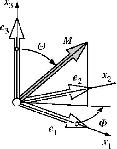
Characterization of an arbitrary unit direction vector M by means of Eulerian angles Θ∈[0,π] and Φ∈[0,2π] in a three-dimensional Cartesian coordinate system {e1, e2, e3}.
The density function ρ(M) is defined such that ρ(M(Θ,Φ))sin ΘdΘdΦ represents the (normalized) number of fibres with orientations in the range [(Θ,Θ+dΘ), (Φ,Φ+dΦ)], and it has to obey the symmetry requirement ρ(M)≡ρ(−M). In addition, it is assumed that ρ(M) is normalized, such that
| (3.13) |
holds, where ω is the unit sphere and dω=sin ΘdΘdΦ.
Subsequently, ρ(M) is limited to general orthotropic distributions, where, without loss of generality, the preferred directions of the distribution are assumed to coincide with the axes {e1, e2, e3} of the underlying Cartesian coordinate system.
For reasons that will become clear in §4.2, we introduce a (symmetric) generalized structure tensor of second order, defined by
| (3.14) |
which represents the fibre distribution. On use of equation (3.12) the generalized structure tensor (3.14) can be written in the compact form
| (3.15) |
where there is summation over i and j from 1 to 3 and the coefficients αij=αji are defined by
| (3.16) |
Consequently, once the density distribution function is given, equations (3.15) and (3.16) allow the computation of the generalized structure tensor H, which is an alternative measure of the fibre distribution. Note that the generalized structure tensor introduced in (3.14) differs significantly from the second-order fabric tensor that is frequently used to approximate the density function ρ(M) in the context of defect distributions (Kanatani 1984; Krajcinovic 1996).
Finally in this section we note that other papers that account for the distribution of fibre orientations are based largely on the work of Lanir (1983) and include Hurschler et al. (1997), Billiar & Sacks (2000) and Sacks (2003). Their approach is very different from that adopted here and, in particular, does not involve the use of invariants. In a recent paper (Freed et al. in press) another approach has been adopted for a single family of fibres (in respect of aortic heart valve tissue), with the construction of the constitutive law having some features in common with the present paper. In particular, it involves a structure tensor that is similar to H.
4. A constitutive model for arterial layers
A constitutive model aims to reflect the basic mechanical properties of a material that result from its internal constitution. Here, we develop a new constitutive model for the arterial wall that reflects its histology and the experimentally observed mechanical properties discussed in §2. In §4.1 we particularize the continuum representation of distributed fibres as a fundamental prelude to the introduction of the new model for the arterial layers that is discussed in §4.2. The associated Kirchhoff stress and the spatial elasticity tensors are then derived in §4.3, which provide the basis for an efficient finite element implementation of the model. We emphasize that we focus only on the passive behaviour of arteries, and in vivo (active) effects are not therefore considered in the present work.
4.1 Transversely isotropic representation of a family of collagen fibres
In this section the continuum representation of distributed collagen fibres, as introduced in §3.4, is particularized. It is assumed that in each arterial layer two families of collagen fibres are embedded. As distinct from Holzapfel et al. (2000, 2002a), the orientations of the collagen fibres within each family are dispersed. For a given family the fibres are distributed with rotational symmetry about a mean referential (preferred) direction, say a0 (a unit vector), so that the family contributes a transversely isotropic character to the overall response of the material. Without loss of generality, we take the preferred direction a0 to coincide with the Cartesian basis vector e3. The density function is then independent of Φ, i.e. ρ(M(Θ,Φ))→ρ(Θ). The normalization condition (3.13) then reduces to , the off-diagonal coefficients α12=α23=α13 of H defined in equation (3.16) vanish, and the diagonal terms remaining are, on use of the normalization condition, given by
| (4.1) |
where the notation κ has been introduced. Consequently, the generalized structure tensor H may be given in the compact form
| (4.2) |
where I denotes the identity tensor. Hence, H depends on a single dispersion (structure) parameter κ, which represents the fibre distribution in an integral sense and describes its ‘degree of anisotropy'. A remarkable result from the above derivation is that every transversely isotropic fibre distribution is represented by a ‘linear mixture' of I and a0⊗a0 according to equation (4.2). In general, we can regard κ as a structure parameter that can be obtained from experimental data, but it is nevertheless instructive to examine the character of the density function ρ(Θ) for a specific distribution of fibre orientations, which we now do in the following.
4.1.1 Illustrative fibre distributions
In order to discuss the dispersion parameter κ we assume that the embedded collagen fibres are distributed according to a transversely isotropic and π-periodic von Mises distribution. Therefore, the standard π-periodic von Mises distribution is modified in order to satisfy the normalization condition (3.13). The resulting density function ρ(Θ) becomes
| (4.3) |
where b>0 is the concentration parameter associated with the von Mises distribution, and erfi(x)=−i erf(x) denotes the imaginary error function (Weisstein 2005), the error function itself being given by
Since the von Mises distribution is the projection of the normal distribution onto the unit circle, the density function (4.3) can be interpreted similarly as a projection of the normal distribution onto the unit sphere (Fisher et al. 1987).
In this remark the derivation of (4.3) from the standard π-periodic von Mises distribution is discussed briefly. We start with a density function for the standard π-periodic von Mises distribution, centered at Θ=0, i.e.
(4.4) where I0(x) denotes the modified Bessel function of the first kind of order zero. Integration of (4.4) according to the normalization condition (3.13) gives, for b>0, the relation
Finally, equation (4.3) is obtained by the normalization of with I, i.e. .
The relation between the dispersion parameter κ and the concentration parameter b is illustrated in figure 3, where κ is plotted against b, κ being computed by numerical integration of (4.1)3 using (4.3). As can be seen from figure 3, there is a one-to-one relation between κ and b for b>0. Note that while the von Mises distribution is defined for b>0, ρ(Θ)→1 as b→0, so that κ=1/3 for b=0 and κ∈[0,1/3].
The lower limit of the dispersion parameter, i.e. κ=0, describes the ideal alignment of collagen fibres, which is represented by b→∞ in (4.3). In this case, the Dirac delta function characterizes the density function, and the generalized structure tensor (4.2) reduces to a0⊗a0. The upper limit of the dispersion parameter, i.e. κ=1/3, describes the isotropic distribution of the collagen fibres, which is represented by b→0 in (4.3). In this case the density function is constant, i.e. ρ≡1, and the generalized structure tensor (4.2) reduces to I.
A graphical representation of the density function (4.3) is provided in figure 4, in which the surface defined by the apex of the vector ρ(M)M is plotted with respect to the Eulerian angles Θ and Φ. Six different distributions are shown, corresponding to κ=0, 1/15, 2/15, 1/5, 4/15, 1/3. In this representation, the isotropic distribution (κ=1/3) gives a sphere, while the ideal aligned fibres (κ=0) are characterized by an infinitely long line in the direction of a0. The transversely isotropic distributions between these limits are characterized by ‘bone-like’ surfaces, where a0 defines their longitudinal axes. Note that for representative purposes the objects shown in figure 4 are scaled differently.
Due to the symmetry about a0 the density function (4.3) can also be represented by means of a two-dimensional plot. Figure 5 shows this representation with respect to the Eulerian angle Θ. Therein, the isotropic distribution of the collagen fibres (κ=1/3) is represented by the horizontal line at ρ=1, while their perfect alignment (κ=0) is characterized by the Dirac delta function. In between these limits the density function is typically ‘bell-shaped’. Note that this type of representation is frequently used in the literature to present histological data, such as experimentally determined collagen distributions for planar collagenous tissues; see, for example, Sacks (2003).
Figure 3.

Relation between the dispersion parameter κ and the concentration parameter b of the (transversely isotropic) von Mises distribution.
Figure 4.

Three-dimensional graphical representation of the orientation of the collagen fibres based on the transversely isotropic density function (4.3).
Figure 5.

Two-dimensional graphical representation of the (transversely isotropic) von Mises distribution of the collagen fibres.
4.2 Anisotropic hyperelastic formulation
The continuum representation of collagen fibre orientations derived above forms the basis for an anisotropic hyperelastic formulation for arterial layers, which will be elaborated in this section. Basically, it follows the concept proposed in Holzapfel & Gasser (2001) and Holzapfel et al. (2000), where an additive split of the energy stored in the groundmatrix and the collagen reinforcement is assumed. However, the underlying structural approach enriches this model by including structural data associated with the dispersion of the embedded collagen fibres.
In the following the modelling assumptions are discussed and their mathematical formulation is introduced. The complex architecture of an arterial layer is represented mechanically as a fibre-reinforced composite (Holzapfel & Gasser 2001; Holzapfel et al. 2000) in which two families of collagen fibres are embedded in an isotropic groundmatrix. Depending on the particular arterial layer the groundmatrix is associated with non-collagenous but mechanically relevant tissue components, such as elastin and smooth muscle cells in the media. For simplicity and in accordance with Holzapfel et al. (2000), we assume that the mean orientations a0i, i=1,2, of the families of collagen fibres have no radial component. Note, however, that this assumption seems not to be supported by arterial histology; see, for example, Canham et al. (1989) and Finlay et al. (1998). Nevertheless, the three-dimensional nature of the distribution adopted implies that there are fibres with a component in the radial direction. An alternative approach for which there is no such component can be developed by adopting a two-dimensional fibre distribution locally within the plane normal to the radial direction. Such a model requires only a slight modification of the structure tensor H but is not considered here.
In order to derive the anisotropic hyperelastic potential for an arterial layer, it is assumed that it can be represented by a superposition of the isotropic potential for the non-collagenous groundmatrix (indicated by subscript ‘g’), and the two transversely isotropic potentials , i=1,2, for the embedded families of collagen fibres (with subscript ‘f’). Hence, the free-energy function, which is formally similar to the formulation introduced in Holzapfel & Gasser (2001) and Holzapfel et al. (2000), is
| (4.5) |
where the general structure tensor Hi(a0i, κ) is defined in accordance with (4.2) and depends on the mean orientation a0i of the embedded ith family of collagen fibres and the dispersion parameter κ (the same for each family).
Following Holzapfel & Weizsäcker (1998), we model the non-collagenous groundmatrix by means of an incompressible isotropic neo-Hookean model, i.e. , where and c denote the first invariant of and the neo-Hookean parameter, respectively. In order to particularize the transversely isotropic free-energy function for the ith family of collagen fibres the form
| (4.6) |
| (4.7) |
is proposed, where denotes an invariant of the symmetric generalized structure tensor Hi and the symmetric modified right Cauchy–Green tensor ; see Spencer (1984) for a general discussion of invariants of this kind. Note that Hi:I=1. Moreover, we introduced the Green-Lagrange strain-like quantity , which characterizes the strain in the direction of the mean orientation a0i of the ith family of fibres. In (4.6), k2>0 is a dimensionless parameter and k1>0 is a stress-like parameter to be determined from mechanical tests of the tissue, while a0i and κ are structure parameters to be determined from histological data of the tissue. A basic assumption in (4.6) is that both families of fibres have the same mechanical properties, i.e. the same set (k1, k2) of parameters is applied. Similarly, the same dispersion parameter κ characterizes the distribution of the collagen fibres within the two families of fibres.
A fundamental hypothesis of the model introduced in Holzapfel & Gasser (2001) and Holzapfel et al. (2000) is that the collagen fibres cannot support any compression and would buckle under the smallest compressive load. This modelling assumption is not only based on physical reasons but is also essential for reasons of stability (Holzapfel et al. 2004a). In order to represent an analogous assumption in the potential (4.6), it is convenient to modify the definition (4.2) of the structure tensor Hi. It is therefore assumed that the anisotropic part (1−3κ)(a0i⊗a0i) contributes to Hi only if the strain in the direction of a0i is positive, i.e. . For κ=0 this assumption is sufficient for convexity of the potential (4.6) (Holzapfel et al. 2004a). While a proof of convexity in the more general case remains to be provided, a simple proof (with certain limitations) is provided in the appendix A.
The media of the arterial wall is composed of smooth muscle cells, elastic sheets and fibrils, and bundles of collagenous fibrils (Rhodin 1980) forming lamellar units (Clark & Glagov 1985). In particular, in elastic arteries fenestrated elastic laminae, about 40–60 in large arteries (Rhodin 1980), give the media a clear laminated structure. In the unstressed tissue the lamellae are folded and straightened successively with increasing stretch (Samila & Carter 1981). The proposed modelling of the non-collagenous groundmatrix by means of an isotropic (neo-Hookean) model seems to be too restrictive a simplification for the medial layer of elastic arteries. Nevertheless, in view of its simplicity, this assumption is adopted here.
In order to show the differences between (4.6) and the anisotropic contribution of the free-energy function, as introduced in Holzapfel & Gasser (2001) and Holzapfel et al. (2000), we replace by . Here is a tensor invariant equal to the square of the stretch in the direction of a0i. Hence, (4.6) reads
which clearly shows that depends on in addition to . This is the most fundamental difference between (4.6) and the formulation introduced in Holzapfel & Gasser (2001) and Holzapfel et al. (2000). Note that for κ=0 the potential (4.6) coincides with that in Holzapfel & Gasser (2001) and Holzapfel et al. (2000).
For κ=1/3 (corresponding to an isotropic distribution), the potential (4.6) becomes
which is similar to that proposed by Demiray (1972), and applied within the context of finite elements by Delfino et al. (1997). The only difference is that (4.6) involves instead of the term in Demiray (1972).
4.3 Kirchhoff stress tensor and spatial elasticity tensor
In order to implement the model in the multi-purpose finite element package Feap (Taylor 2000), expressions for the underlying Kirchhoff stress and spatial elasticity tensor are required. These are now summarized. The continuum mechanical framework, as introduced in §3, and the particularized free-energy function, as proposed in §4.2, form the points of departure. Due to the incompressibility assumption of the arterial wall we focus on the isochoric contributions and , as defined in equations (3.8)3 and (3.11)2, respectively.
4.3.1 Kirchhoff stress tensor
As already mentioned, the non-collagenous groundmatrix is represented by a standard neo-Hookean model. Hence, the isochoric Kirchhoff stress response reads , with , a well-known result from the literature; see, for example, Miehe (1996). In order to particularize the contribution to the Kirchhoff stress tensor associated with the potential of the ith family of fibres, i.e. (4.6), the scalar stress function is introduced so that holds. Based on the above result, equation (3.8) gives, with the help of equations (3.3) and (3.4), the final result
| (4.8) |
for the contribution of the ith family of fibres to the Kirchhoff stress tensor. Here, the push-forward of the structure tensor via the unimodular part of the deformation has been used. Based on this definition, the Green-Lagrange strain-like quantity , as introduced in (4.7)1, can be rewritten as .
4.3.2 Elasticity tensor
The contribution of the non-collagenous groundmatrix to the isochoric elasticity tensor is given by
a well-known result for the neo-Hookean model; see, for example, Miehe (1996).
The application of equation (3.11)2 for the potential of the ith family of fibres, i.e. (4.6), gives the associated contribution to the isochoric elasticity tensor. In order to particularize the first part of (3.11)2, i.e. , the scalar elasticity function is introduced so that
In order to proceed, we apply the definition and particularize the Eulerian (fictitious) elasticity tensor, i.e.
which leads to . Based on this (surprisingly simple) result the first contribution of the ith family of fibres to the isochoric elasticity tensor becomes
| (4.9) |
The contributions, and , from the second and third terms in equation (3.11)2 can be obtained immediately by using the results (4.8). It is worth noting that the Kirchhoff stress and the elasticity tensors are formally similar to the corresponding quantities in the fibre-reinforced model (Holzapfel et al. 2000); see, for example, the elastic part of the response presented by Gasser & Holzapfel (2002).
With the major and minor symmetries of the elasticity tensor contributions accounted for, they can be implemented efficiently in a finite element code, as was done with Feap (Taylor 2000). For completeness, the quantities required for the implementation in an Eulerian setting are summarized in table 2.
Table 2.
Summary of the quantities required for an efficient finite element implementation in an Eulerian setting.
| deformation measures |
| structure tensors |
| structure strain invariants |
| stress and elasticity functions |
| isochoric Kirchhoff stress tensor |
| isochoric spatial elasticity tensor |
5. Examples
5.1 Inflation of a thin-walled tube
In this section the inflation of a thin-walled tube characterized by the proposed anisotropic constitutive model (4.6) is investigated. In particular, the influence of the structure parameters a0i and κ on the global response of the tube is discussed. From previous studies with perfectly aligned fibres (κ=0) it is known that variation of the mean orientations a0i of the families of fibres has a significant influence on the global response of the tube (Holzapfel & Gasser 2001). As mentioned, κ characterizes the dispersion of the collagen fibres of each family, and hence it controls the degree of anisotropy of the hyperelastic formulation, which certainly has a significant influence on the mechanical response.
Throughout this example, a membrane approximation of an iliac adventitia is adopted, with the geometry of the reference (and stress-free) configuration described by the mean radius R=4.745 mm and the wall thickness H=0.43 mm. The geometrical data are taken from Schulze-Bauer et al. (2003) and a sketch of the thin-walled tube problem is shown in figure 6. Moreover, it is assumed that the two families of collagen fibres are embedded symmetrically, with γ denoting the angle between the circumference and the mean orientation a0i of the fibre families.
Figure 6.
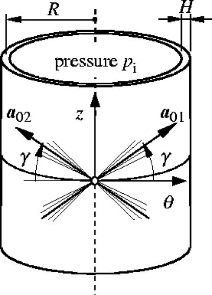
Thin-wall approximation of the inflation of the adventitial layer with two embedded families of fibres. The mean orientations and the dispersion of the collagen fibres are characterized by γ and κ, respectively.
With no applied axial load and for an internal pressure pi, the associated equilibrium conditions in the axial and circumferential directions are (Holzapfel & Gasser 2001)
| (5.1) |
where λz and λθ denote the axial and circumferential stretches, respectively. In (5.1) the energy function
| (5.2) |
is introduced, which is derived from (4.6) by application of the incompressibility constraint and arguments of symmetry. Equations (5.1) and (5.2) define a system of nonlinear equations that need to be solved numerically for a prescribed internal pressure pi (using, for example, the Newton–Raphson method).
The investigation of the proposed constitutive model is based on solving the underlying equilibrium equations in Mathematica (2005). It is assumed that the material parameters c=7.64 kPa, k1=996.6 kPa, k2=524.6 and the structure parameters γ=49.98°, κ=0.226 describe the mechanical response of the iliac adventitia. The parameters are based on least-squares fitting of longitudinal and circumferential tension tests of adventitial strips of nine iliac arteries (Holzapfel et al. 2004b). It needs to be emphasized that the structure parameters γ and κ are identified from the macroscopic mechanical response rather than from the underlying histology of the iliac adventitia. The investigation of potential (4.6) with respect to the structure parameters is carried out for κ=0, 0.226, 0.333 and γ=39.98°, 49.98°, 59.98°, with the material parameters c, k1, k2 as given above.
The results of this study are illustrated in figure 7 in terms of internal pressure/axial stretch (p/λz) and internal pressure/circumferential stretch (p/λθ) plots. For κ=0.333 (isotropic distribution of the orientation of the collagen fibres) the different mean orientations (indicated by different angles γ) lose their meaning and the response of the tube is isotropic (solid curves in figure 7).
Figure 7.
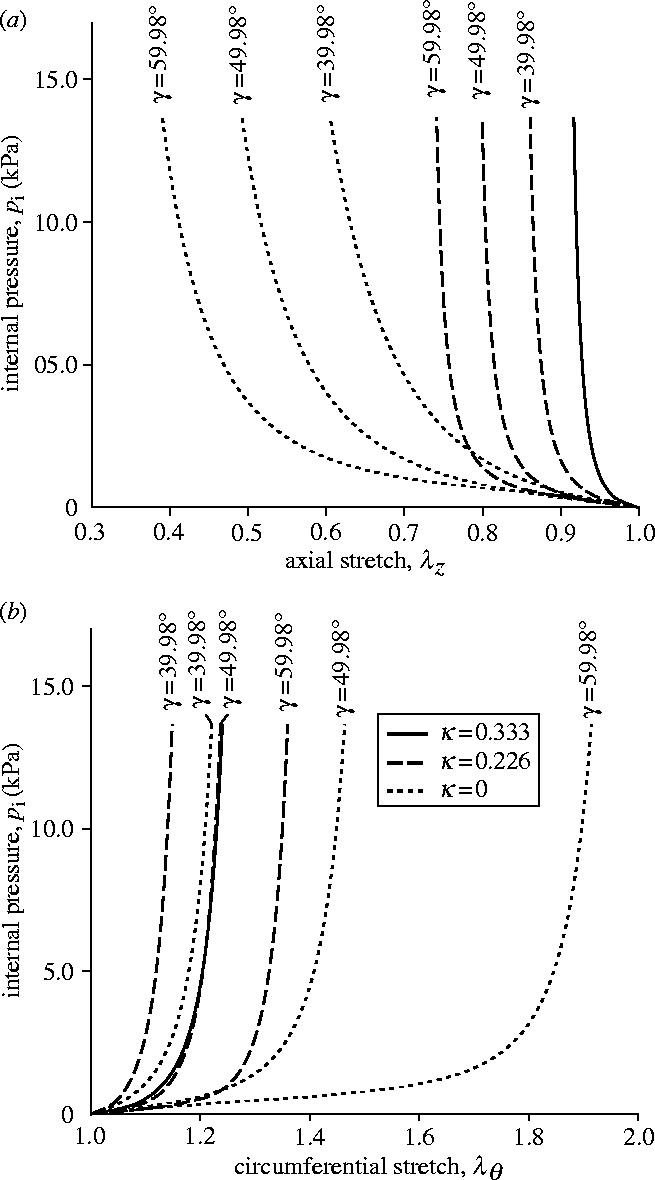
Influence of collagen fibre mean alignment γ and dispersion κ on the mechanical response of a thin-walled tube. Solid curves: isotropic tube (κ=1/3). Dashed and dotted curves: anisotropic response corresponding to κ=0.226 and 0, respectively.
By contrast, the response of the tube for κ=0.226 and 0 varies with the mean orientation γ, as expected from the anisotropic nature of the hyperelastic formulation (in figure 7 dashed and dotted curves correspond to κ=0.226, 0, respectively). As with the findings in Holzapfel & Gasser (2001), it can be seen clearly that the response of the tube reinforced by perfectly aligned fibres (κ=0) depends strongly on the mean orientation γ. In particular, at an internal pressure of 13.67 kPa and at γ=39.98° the axial and circumferential stretches are computed as 0.605 and 1.221, respectively. Changing the mean alignment by +20°, to γ=59.98°, with the same loading gives axial and circumferential stretches of 0.391 and 1.914, respectively.
A major effect of including dispersion of the collagen fibres is a decrease in the dependence of the response of the tube on the mean alignment γ. In particular, for κ=0.226 an internal pressure of 13.67 kPa gives axial and circumferential stretches of 0.861 and 1.149, respectively, for γ=39.98°, and 0.741 and 1.360 for γ=59.98°. For the isotropic distribution of collagen (κ=0.333) the response is independent of γ. This case aside, from figure 7 it can be seen that the pressure/circumferential stretch response stiffens as the mean orientation approaches the circumferential direction, and the tube also has a tendency to stiffen with increasing κ.
5.2 Simple tension of iliac adventitial strips
In this section uniaxial tensile tests performed on adventitial strips from the circumferential and axial directions are considered. In particular, a finite element computation is used to investigate uniaxial strip tests related to experiments performed in our laboratory. These simple examples illustrate the consequences of the proposed (generalized) constitutive formulation when compared with the (original) potential introduced in Holzapfel & Gasser (2001) and Holzapfel et al. (2000), and, in particular, the differences in their load carrying mechanisms.
For the experiments, circumferential and axial specimens cut from the dissected adventitial layer, as illustrated schematically in figure 8, were used. We assume that the material and structural properties do not change over the adventitial patch. In addition, we assume that the vectors a01 and a02, which represent the mean orientations of the families of collagen fibres, have no radial component, i.e. they are embedded in the (θ,z) plane.
Figure 8.

Definition of circumferential and axial specimens for the tensile tests.
For the numerical investigation, the material parameters c=7.64 kPa, k1=996.6 kPa, k2=524.6 and the structure parameters γ=49.98°, κ=0 and κ=0.226 for an iliac adventitia are considered. It is emphasized that the ideally aligned collagen reinforcement (κ=0) is considered for comparative purposes only and does not describe the mechanics of adventitial tissue. The tensile tests are modelled by means of three-dimensional finite element computations based on the implementation of the dispersed fibre model using Feap (Taylor 2000). Adventitial strips of referential length L=10.0 mm, referential width W=3.0 mm and referential thickness T=0.5 mm are considered throughout this study. The mounting of the specimen in the testing machine is modelled by constraining both ends of the strip. The strips are loaded in the tensile direction and their end faces are not allowed to deform. The quasi-static solution of the resulting nonlinear problem is computed by means of the Newton–Raphson method.
The finite element computations use 3200 hexahedral elements, which are based on a three-field Hu-Washizu variational formulation (Holzapfel 2000). This formulation is best suited for capturing the quasi-incompressible deformation of soft biological tissues. In particular, the mixed finite element Q1/P0 is applied throughout this investigation. In order to avoid ill-conditioning of the finite element stiffness matrix associated with standard penalty methods that enforce the incompressibility constraint, an augmented Lagrangian method is applied using an Uzawa algorithm (Simo & Taylor 1991).
5.2.1 Results for the ideal collagen fibre alignment (κ=0)
Figure 9 shows the computed Cauchy stress in the tensile direction in the circumferential and axial specimens, where the outlines of the undeformed configurations, shown by solid lines, are superimposed. The results are presented for a tensile load of 1.0 N, and perfect alignment of the collagen fibres within each family has been assumed (κ=0).
Figure 9.
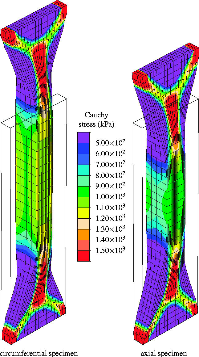
Finite element computation of a uniaxial tension test on an iliac adventitial strip in the circumferential and axial directions. The Cauchy stress in the direction of the applied load is plotted for a 1.0 N tensile load, and no dispersion of the collagen fibres is taken into account (κ=0).
The embedded collagen fibres need to rotate nearly into the loading direction before they can carry load (see the discussion in §2.3.1). This causes a large extension in the radial direction, and hence the thickness of the specimen increases, as can be seen clearly in the middle of the strips. In addition, due to the incompressibility constraint, the width of the specimens decreases. The matrix material, characterized by the neo-Hookean parameter c=7.64 kPa, supports this deformation mechanism since it is too soft to prevent the large rotation of the collagen fibres. At the ends of the strip transition zones have evolved that are very similar to those observed in woven fabrics (Milani & Nemes 2004). Figure 10 represents the current collagen alignment, where the scalar product ca=a1·a2 of the current orientation vectors is plotted. It can be seen that the alignment of the collagen fibres in the middle of the strips is characterized by ca>0.9 for no dispersion of the collagen fibres (κ=0). Moreover, the computation showed maximum values of ca=0.914 and ca=0.917 for the circumferential and the axial specimens (figure 10a). These values are associated with angles between the loading direction and the current collagen fibre orientations of 11.97 and 11.75°, respectively.
Figure 10.

Finite element prediction of the current (mean) collagen orientations using the parameter ca=a1·a2. Results are shown for circumferential and axial specimens at 1.0 N tensile load: (a) no dispersion of the collagen fibres (κ=0); (b) dispersion of the collagen fibres within each family (κ=0.226).
Figure 11 illustrates the predicted tensile load/displacement (T/u) response, where dotted curves are results for κ=0. Here u and T denote the (prescribed) displacement at the end of the specimen and the force acting there, respectively. Until the collagen fibres are approximately aligned with the tensile direction the material is relatively soft and only a small force is needed to achieve significant extension. In particular, for the circumferential specimen the alignment requires large average stretches, and hence the specimen stiffens at about u=4 mm.
Figure 11.
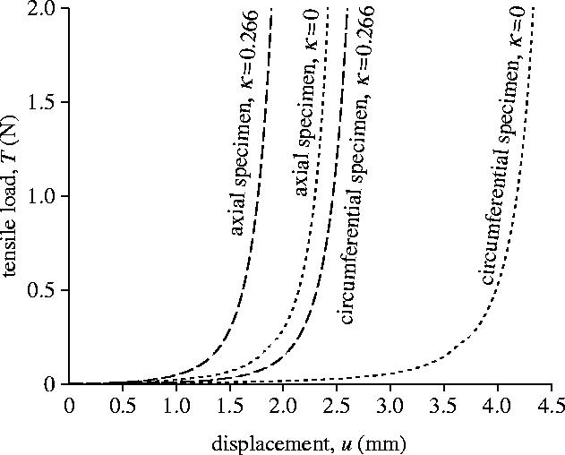
Computed tensile load/displacement (T/u) response of the circumferential and axial specimens. Dashed and dotted curves are with (κ=0.266) and without (κ=0) dispersion of the collagen fibres.
5.2.2 Results for the dispersed collagen fibre alignment (κ=0.226)
Figure 12 illustrates the computed Cauchy stress in the tensile direction in the circumferential and axial specimens at a tensile load of 1.0 N. The outlines of the undeformed configurations are included, and a dispersed alignment of the collagen fibres within each family has been assumed (κ=0.226).
Figure 12.
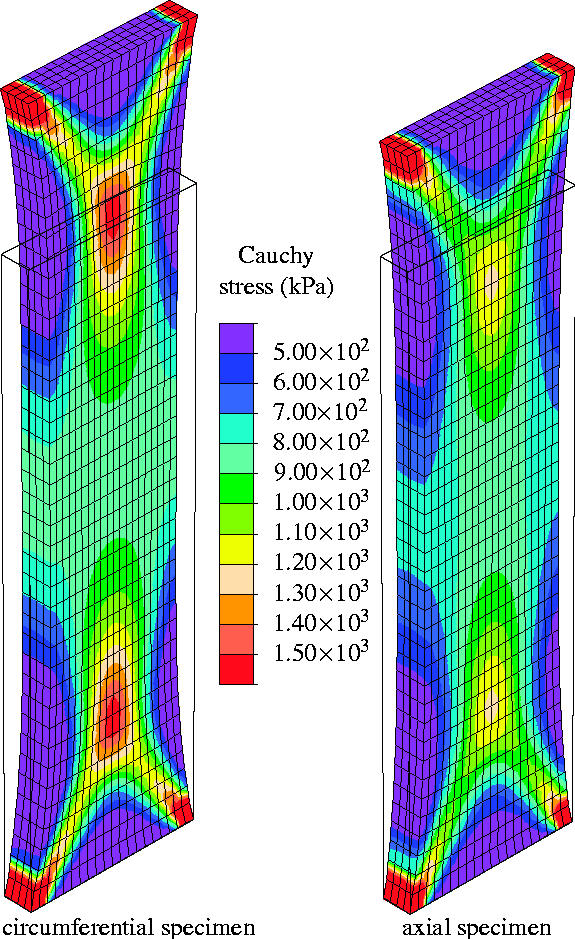
Finite element computation of the Cauchy stress in the direction of the applied load in an iliac adventitial strip in the circumferential and axial directions. Results are shown for 1.0 N tensile load and dispersion of the collagen fibres is included (κ=0.226).
As can be seen from figure 12 the thickness of the specimens remains approximately constant during loading, which is in contrast to the results for ideally aligned fibres (see figure 9). The transition zones at the ends of the strips are smaller and have different shapes from those in figure 9.
Figure 10b represents the current alignment of the mean orientations of the embedded families of collagen fibres. It can be seen that in the circumferential and axial specimens the alignment of the collagen fibres in the middle of the strips is characterized by ca>0.34 and ca>0.42. The associated maximum values are ca=0.353 and ca=0.497, which correspond to angles between the loading direction and the current mean orientations of 34.66° and 30.10°, respectively. Compared with the results of the computation for ideally aligned collagen fibres, these values indicate much less rotation of the (mean) collagen orientations.
The computed tensile load/displacement (T/u) response for the dispersed collagen fibre alignment (κ=0.226) is illustrated by the dashed curves in figure 11. As already discussed, less rotation of the collagen fibres is required before they carry load compared with the ideally aligned case. Hence, similarly to the results shown in §5.1, the dispersion of the collagen fibres leads to a stiffer response of the specimens. In particular, the distribution parameter κ controls the location of the transition point, i.e. the stretch at which the specimen stiffens. Hence, the stiffening of adventitial strips in the circumferential and axial directions can be predicted within the experimentally observed range of stretches.
6. Conclusions
The development of constitutive laws for modelling the mechanical properties of arterial tissue is central for improving understanding of, for example, the load carrying mechanisms of the arterial wall and the adaptation of the wall to altered mechanical loading from both the physiological and pathological points of view. It is also essential for the successful application of the theory to the solution of boundary-value problems that are associated with mechanically dominated clinical procedures such as percutaneous transluminal angioplasty. Moreover, the development of structurally-based models is a prerequisite for understanding the interrelationships between function and structure within an artery and the changes in those interrelations under changes in the mechanical environment.
In the light of improved information on the structural arrangement within different arterial layers of the arterial wall, in particular the significant dispersion of the orientations of the collagen fibres within the intima and the adventitia, we have developed a structural model based on the nonlinear theory of anisotropic elasticity that is able to account for this dispersion in a relatively simple way on the basis of a generalized structure tensor. The model has been particularized so that the fibre orientations within each family of fibres generate locally a transversely isotropic distribution. This has the advantage that it requires only a single scalar structure parameter to describe the dispersion of the fibres and enables the typical nonlinear material responses of the tissue in each layer of the artery to be captured. The formulation developed here is a generalization of the anisotropic formulation introduced in Holzapfel et al. (2000) and Holzapfel & Gasser (2001). The required expressions for an efficient finite element representation of the proposed constitutive model have been derived and implemented in Feap (Taylor 2000).
Two representative numerical examples have been used to illustrate the mechanical response obtained from the proposed formulation. For this purpose we have chosen material parameters that have been obtained from recent experiments on the adventitia of human iliac arteries in our laboratory. In the first example the inflation of a thin-walled tube is modelled with the particular objective of illustrating the influence of the two structure parameters—the mean orientation of the families of collagen fibres, and the dispersion of the collagen fibre orientation within the fibre families—on its mechanical response. It was found that each structure parameter has a significant influence on the pressure-diameter and pressure-length behaviour of the tube. In particular, the computations showed that a larger dispersion increases the stiffness of the tube but decreases the dependence of its response on the mean orientation of the families of collagen fibres.
In the second example, a finite element simulation of an experimental tensile test on adventitial strips was performed to determine the influence of the dispersion of the collagen fibre orientation on the mechanical response. It was found that an ideal alignment of the collagen fibres (zero dispersion) causes large rotations of the fibres before they carry load. This mechanism is partly supported by a soft matrix material and leads to deformation patterns typical of woven fabrics rather than of soft tissues. Consequently, in order to carry load, the collagen fibres need to be rotated closer to the direction of the tensile load. Hence, the stiffening of adventitial strips in the circumferential and axial directions (within the typical range of stretches) cannot generally be predicted with a model that uses ideally aligned fibres (zero dispersion). On the other hand, the computation was able to replicate the stiffening of adventitial tissue (within the typical range of stretches) when taking the diversity of collagen orientation into account. Based on that capability, it seems that the present model is able to capture the main features of the load carrying mechanisms of adventitial tissue.
Finally, it should be noted that quantification of the structure parameters for this investigation was based on macroscopic mechanical tests rather than on an alternative method, such as histological investigations involving staining of adventitial tissue. A reliable assessment of the applicability of the proposed model for capturing the mechanical response of arterial layers requires structural and mechanical data from the same specimen, which are not yet available in the literature.
This latter point needs to be emphasized since there is a need for more detailed microstructural information in order to inform the further development of constitutive models. In particular, more quantitative information on the distribution of collagen fibre orientations within the different layers, and details of how individual collagen fibres, fibre bundles and their interactions respond under applied loads are needed. A clearer picture of geometrical and structural changes under load is called for; for some recent results, see Schmid et al. (in press). It is also particularly important to know more about the residual stress distributions, especially in three dimensions, that have such a crucial influence on the response of arteries under normal and pathological conditions.
Acknowledgments
Financial support for this research was partly provided by the Austrian Science Foundation under START-Award Y74-TEC and by the Royal Society. This support is gratefully acknowledged.
Appendix A. Convexity of (4.6)
We consider here the convexity of (4.6), with (4.7), in a restricted sense, with the material considered as incompressible. For this purpose we simplify the notation by writing
where
λ1 and λ2 are the independent principal stretches and the mean direction of the fibres is given by the unit vector a0 with components (cos γ, sin γ, 0) referred to the principal axes of the right Cauchy–Green tensor C. We are assuming here that a0 lies is the (λ1, λ2) principal plane. Since k1>0 and k2>0, it follows that ψ′(E)>0, ψ″(E)>0.
Let . Then, with subscripts 1 and 2 signifying partial derivatives with respect to λ1 and λ2, respectively, we have
A short calculation shows that E11>0, and hence follows. It remains to consider the Hessian determinant , which can be rewritten as
It is easy to show that E12>0 and and hence
Thus, and is a strictly convex function of λ1 and λ2.
Footnotes
The term groundmatrix is used here to include all the material except collagen, in contrast to usage in the medical literature, which implies exclusion of cells.
It is worth noting that throughout this paper the orientation of collagen fibres is defined as the average orientation of the corrugated fibre in the stress-free (reference) configuration. In particular, the waviness of the collagen fibres should be distinguished from the dispersion of their orientations.
References
- Abè H, Hayashi K, Sato M. Springer; New York: 1996. Data book on mechanical properties of living cells, tissues, and organs. [Google Scholar]
- Bergel, D. H. 1960 The visco-elastic properties of the arterial wall. Ph.D. thesis, University of London.
- Billiar K.L, Sacks M.S. Biaxial mechanical properties of the native and glutaraldehyde-treated aortic valve cusp: Part II-A structural constitutive model. J. Biomech. Eng. 2000;122:327–335. doi: 10.1115/1.1287158. [DOI] [PubMed] [Google Scholar]
- Block P.C. Mechanism of transluminal angioplasty. Am. J. Cardiol. 1984;53:69C–71C. doi: 10.1016/0002-9149(84)90750-1. [DOI] [PubMed] [Google Scholar]
- Butler D.L, Goldstein S.A, Guilak F. Functional tissue engineering: the role of biomechanics. J. Biomech. Eng. 2000;122:570–575. doi: 10.1115/1.1318906. [DOI] [PubMed] [Google Scholar]
- Canham P.B, Finlay H.M, Dixon J.G, Boughner D.R, Chen A. Measurements from light and polarised light microscopy of human coronary arteries fixed at distending pressure. Cardiovasc. Res. 1989;23:973–982. doi: 10.1093/cvr/23.11.973. [DOI] [PubMed] [Google Scholar]
- Carew T.E, Vaishnav R.N, Patel D.J. Compressibility of the arterial wall. Circ. Res. 1968;23:61–68. doi: 10.1161/01.res.23.1.61. [DOI] [PubMed] [Google Scholar]
- Chuong C.J, Fung Y.C. Three-dimensional stress distribution in arteries. J. Biomech. Eng. 1983;105:268–274. doi: 10.1115/1.3138417. [DOI] [PubMed] [Google Scholar]
- Chuong C.J, Fung Y.C. Compressibility and constitutive equation of arterial wall in radial compression experiments. J. Biomech. 1984;17:35–40. doi: 10.1016/0021-9290(84)90077-0. [DOI] [PubMed] [Google Scholar]
- Chuong C.J, Fung Y.C. On residual stress in arteries. J. Biomech. Eng. 1986;108:189–192. doi: 10.1115/1.3138600. [DOI] [PubMed] [Google Scholar]
- Clark J.M, Glagov S. Structural integration of the arterial wall. Lab. Invest. 1979;40:587–602. [PubMed] [Google Scholar]
- Clark J.M, Glagov S. Transmural organization of the arterial media: the lamellar unit revisited. Arteriosclerosis. 1985;5:19–34. doi: 10.1161/01.atv.5.1.19. [DOI] [PubMed] [Google Scholar]
- Cox R.H. Regional variation of series elasticity in canine arterial smooth muscles. Am. J. Physiol. 1978;234:H542–H551. doi: 10.1152/ajpheart.1978.234.5.H542. [DOI] [PubMed] [Google Scholar]
- Decraemer W.F, Maes M.A, Vanhuyse V.J. An elastic stress–strain relation for soft biological tissues based on a structural model. J. Biomech. 1980;13:463–468. doi: 10.1016/0021-9290(80)90338-3. [DOI] [PubMed] [Google Scholar]
- Delfino A, Stergiopulos N, Moore J.E, Jr, Meister J.-J. Residual strain effects on the stress field in a thick wall finite element model of the human carotid bifurcation. J. Biomech. 1997;30:777–786. doi: 10.1016/S0021-9290(97)00025-0. [DOI] [PubMed] [Google Scholar]
- Demiray H. A note on the elasticity of soft biological tissues. J. Biomech. 1972;5:309–311. doi: 10.1016/0021-9290(72)90047-4. [DOI] [PubMed] [Google Scholar]
- Finlay H.M, McCullough L, Canham P.B. Three-dimensional collagen organization of human brain arteries at different transmural pressures. J. Vasc. Res. 1995;32:301–312. doi: 10.1159/000159104. [DOI] [PubMed] [Google Scholar]
- Finlay H.M, Whittaker P, Canham P.B. Collagen organization in the branching region of human brain arteries. Stroke. 1998;29:1595–1601. doi: 10.1161/01.str.29.8.1595. [DOI] [PubMed] [Google Scholar]
- Fisher N.I, Lewis T.L, Embleton B.J.J. Cambridge University Press; Cambridge: 1987. Statistical analysis of spherical data. [Google Scholar]
- Flory P.J. Thermodynamic relations for highly elastic materials. Trans. Faraday Soc. 1961;57:829–838. doi: 10.1039/tf9615700829. [DOI] [Google Scholar]
- Freed, A. D., Einstein, D. R. & Vesely, I. In press. Invariant formulation for dispersed transverse isotropy in aortic heart valves. An efficient means for modeling fiber splay. Biomech. Model. Mechanobiol. [DOI] [PubMed]
- Fuchs R.F. Zur Physiologie und Wachstumsmechanik des Blutgefäßsystems. Arch. Ges. Physiol. 1900;28 [Google Scholar]
- Fung Y.C. 2nd edn. Springer; New York: 1993. Biomechanics: mechanical properties of living tissue. [Google Scholar]
- Fung Y.C, Fronek K, Patitucci P. Pseudoelasticity of arteries and the choice of its mathematical expression. Am. J. Physiol. 1979;237:H620–H631. doi: 10.1152/ajpheart.1979.237.5.H620. [DOI] [PubMed] [Google Scholar]
- Gasser T.C, Holzapfel G.A. A rate-independent elastoplastic constitutive model for (biological) fiber-reinforced composites at finite strains: continuum basis, algorithmic formulation and finite element implementation. Comput. Mech. 2002;29:340–360. doi: 10.1007/s00466-002-0347-6. [DOI] [Google Scholar]
- Gasser T.C, Schulze-Bauer C.A.J, Holzapfel G.A. A three-dimensional finite element model for arterial clamping. J. Biomech. Eng. 2002;124:355–363. doi: 10.1115/1.1485284. [DOI] [PubMed] [Google Scholar]
- Glagov S, Zarins C.K, Masawa N, Xu C.P, Bassiouny H, Giddens D.P. Mechanical functional role of non-atherosclerotic intimal thickening. Front. Med. Biol. Eng. 1993;5:37–43. [PubMed] [Google Scholar]
- Greenwald S.E, Moore J.E, Jr, Rachev A, Kane T.P.C, Meister J.-J. Experimental investigation of the distribution of residual strains in the artery wall. J. Biomech. Eng. 1997;119:438–444. doi: 10.1115/1.2798291. [DOI] [PubMed] [Google Scholar]
- Hartman J.D. Structural changes within the media of coronary arteries related to intimal thickening. Am. J. Pathology. 1977;89:13–34. [PMC free article] [PubMed] [Google Scholar]
- Hayashi K. Mechanical properties of soft tissues and arterial walls. In: Holzapfel G.A, Ogden R.W, editors. Biomechanics of soft tissue in cardiovascular systems. Springer; Wien: 2003. pp. 15–64. CISM Courses and Lectures No. 441. [Google Scholar]
- Holzapfel G.A. A continuum approach for engineering. Wiley; Chichester: 2000. Nonlinear solid mechanics. [Google Scholar]
- Holzapfel G.A, Gasser T.C. A viscoelastic model for fiber-reinforced composites at finite strains: continuum basis, computational aspects and applications. Comput. Meth. Appl. Mech. Eng. 2001;190:4379–4403. doi: 10.1016/S0045-7825(00)00323-6. [DOI] [Google Scholar]
- Holzapfel G.A, Ogden R.W. Springer; Wien: 2003. Biomechanics of soft tissue in cardiovascular systems. CISM courses and lectures no. 441. [Google Scholar]
- Holzapfel G.A, Ogden R.W. Springer; Heidelberg: In press. Mechanics of biological tissue. [Google Scholar]
- Holzapfel, G. A. & Ogden, R. W. Submitted. Three-dimensional residual stress distributions of human aorta layers: a mathematical model.
- Holzapfel G.A, Weizsäcker H.W. Biomechanical behavior of the arterial wall and its numerical characterization. Comput. Biol. Med. 1998;28:377–392. doi: 10.1016/S0010-4825(98)00022-5. [DOI] [PubMed] [Google Scholar]
- Holzapfel G.A, Gasser T.C, Ogden R.W. A new constitutive framework for arterial wall mechanics and a comparative study of material models. J. Elast. 2000;61:1–48. doi: 10.1023/A:1010835316564. [DOI] [Google Scholar]
- Holzapfel G.A, Gasser T.C, Stadler M. A structural model for the viscoelastic behavior of arterial walls: continuum formulation and finite element analysis. Eur. J. Mech. A/Solids. 2002a;21:441–463. doi: 10.1016/S0997-7538(01)01206-2. [DOI] [Google Scholar]
- Holzapfel G.A, Stadler M, Schulze-Bauer C.A.J. A layer-specific three-dimensional model for the simulation of balloon angioplasty using magnetic resonance imaging and mechanical testing. Ann. Biomed. Eng. 2002b;30:753–767. doi: 10.1114/1.1492812. [DOI] [PubMed] [Google Scholar]
- Holzapfel G.A, Gasser T.C, Ogden R.W. Comparison of a multi-layer structural model for arterial walls with a Fung-type model, and issues of material stability. J. Biomech. Eng. 2004a;126:264–275. doi: 10.1115/1.1695572. [DOI] [PubMed] [Google Scholar]
- Holzapfel G.A, Sommer G, Regitnig P. Anisotropic mechanical properties of tissue components in human atherosclerotic plaques. J. Biomech. Eng. 2004b;126:657–665. doi: 10.1115/1.1800557. [DOI] [PubMed] [Google Scholar]
- Holzapfel, G. A., Sommer, G., Auer, M. & Regitnig, P. Submitted. Layer-specific three-dimensional geometry of dissected human aortas with intimal thickening.
- Holzapfel, G. A., Sommer, G., Gasser, T. C. & Regitnig, P. In press. Determination of the layer-specific mechanical properties of human coronary arteries with non-atherosclerotic intimal thickening, and related constitutive modelling. Am. J. Physiol.. [DOI] [PubMed]
- Horgan C.O, Saccomandi G. A description of arterial wall mechanics using limiting chain extensibility constitutive models. Biomech. Model. Mechanobiol. 2003;1:251–266. doi: 10.1007/s10237-002-0022-z. [DOI] [PubMed] [Google Scholar]
- Humphrey J.D. Stress, strain and mechanotransduction in cells. J. Biomech. Eng. 2001;123:638–641. doi: 10.1115/1.1406131. [DOI] [PubMed] [Google Scholar]
- Humphrey J.D. Cells, tissues, and organs. New York; Springer: 2002. Cardiovascular solid mechanics. [Google Scholar]
- Humphrey J.D. Continuum biomechanics of soft biological tissues. Proc. R. Soc. A. 2003;459:1–44. doi: 10.1098/rspa.2002.1060. [DOI] [Google Scholar]
- Humphrey J.D, Canham P.B. Structure, mechanical properties and mechanics of intracranial saccular aneurysms. J. Elast. 2000;61:49–81. [Google Scholar]
- Humphrey J.D, Rajagopal K.R. A constrained mixture model for growth and remodeling of soft tissues. Math. Model Meth. Appl. Sci. 2002;12:407–430. doi: 10.1142/S0218202502001714. [DOI] [Google Scholar]
- Humphrey J.D, Rajagopal K.R. A constrained mixture model for arterial adaptations to a sustained step change in blood flow. Biomech. Model. Mechanobiol. 2004;2:109–126. doi: 10.1007/s10237-003-0033-4. [DOI] [PubMed] [Google Scholar]
- Hurschler C, Loitz-Ramage B, Vanderby R., Jr A structurally based stress-stretch relationship for tendon and ligament. J. Biomech. Eng. 1997;119:392–399. doi: 10.1115/1.2798284. [DOI] [PubMed] [Google Scholar]
- Kanatani K.-I. Distribution of directional data and fabric tensors. Int. J. Eng. Sci. 1984;22:149–164. doi: 10.1016/0020-7225(84)90055-7. [DOI] [Google Scholar]
- Krajcinovic D. North-Holland; Amsterdam: 1996. Damage mechanics. [Google Scholar]
- Lanir Y. Constitutive equations for fibrous connective tissues. J. Biomech. 1983;16:1–12. doi: 10.1016/0021-9290(83)90041-6. [DOI] [PubMed] [Google Scholar]
- Lanir Y, Lichtenstein O, Imanuel O. Optimal design of biaxial tests for structural material characterization of flat tissues. J. Biomech. Eng. 1996;118:41–47. doi: 10.1115/1.2795944. [DOI] [PubMed] [Google Scholar]
- Lubarda V.A, Hoger A. On the mechanics of solids with a growing mass. Int. J. Solids Struct. 2002;39:4627–4664. doi: 10.1016/S0020-7683(02)00352-9. [DOI] [Google Scholar]
- Mathematica 5.1.2005 Wolfram Research, Inc.
- Miehe C. Aspects of the formulation and finite element implementation of large strain isotropic elasticity. Int. J. Numer. Methods Eng. 1994;37:1981–2004. doi: 10.1002/nme.1620371202. [DOI] [Google Scholar]
- Miehe C. Multisurface thermoplasticity for single crystals at large strains in terms of Eulerian vector updates. Int. J. Solids Struct. 1996;33:3103–3130. doi: 10.1016/0020-7683(95)00274-X. [DOI] [Google Scholar]
- Milani A.S, Nemes J.A. An intelligent inverse method for characterization of textile reinforced thermoplastic composites using a hyperelastic constitutive model. Compos. Sci. Technol. 2004;64:1565–1576. doi: 10.1016/j.compscitech.2003.11.010. [DOI] [Google Scholar]
- Ogden R.W. Nearly isochoric elastic deformations: application to rubberlike solids. J. Mech. Phys. Solids. 1978;26:37–57. doi: 10.1016/0022-5096(78)90012-1. [DOI] [Google Scholar]
- Ogden R.W. Dover; New York: 1997. Non-linear elastic deformations. [Google Scholar]
- Oktay H.S, Kang T, Humphrey J.D, Bishop G.G. ASME 1991 Biomechanics Symp., AMD. vol. 120. American Society of Mechanical Engineers; New York: 1991. Changes in the mechanical behavior of arteries following balloon angioplasty. [Google Scholar]
- Patel D.J, Fry D.L. The elastic symmetry of arterial segments in dogs. Circ. Res. 1969;24:1–8. doi: 10.1161/01.res.24.1.1. [DOI] [PubMed] [Google Scholar]
- Plenz G.A.M, Deng M.C, Robenek H, Völker W. Vascular collagens: spotlight on the role of type VIII collagen in atherogenesis. Atherosclerosis. 2003;166:1–11. doi: 10.1016/S0021-9150(01)00766-3. [DOI] [PubMed] [Google Scholar]
- Rachev A. Theoretical study of the effect of stress-dependent remodeling on arterial geometry under hypertensive conditions. J. Biomech. 1997;30:819–827. doi: 10.1016/S0021-9290(97)00032-8. [DOI] [PubMed] [Google Scholar]
- Rhodin J.A.G. Architecture of the vessel wall. In: Bohr D.F, Somlyo A.D, Sparks H.V, editors. Handbook of physiology, the cardiovascular system. vol. 2. American Physiological Society; Bethesda: 1980. pp. 1–31. [Google Scholar]
- Roach M.R, Burton A.C. The reason for the shape of the distensibility curve of arteries. Can. J. Biochem. Physiol. 1957;35:681–690. [PubMed] [Google Scholar]
- Roach M.R, Song S.H. Variations in strength of the porcine aorta as a function of location. Clin. Invest. Med. 1994;17:308–318. [PubMed] [Google Scholar]
- Roy C.S. The elastic properties of the arterial wall. J. Physiol. 1880–82;3:125–159. doi: 10.1113/jphysiol.1881.sp000088. [DOI] [PMC free article] [PubMed] [Google Scholar]
- Sacks M.S. Incorporation of experimentally-derived fiber orientation into a structural constitutive model for planar collagenous tissues. J. Biomech. Eng. 2003;125:280–287. doi: 10.1115/1.1544508. [DOI] [PubMed] [Google Scholar]
- Samila Z.J, Carter S.A. The effect of age on the unfolding of elastin lamellae and collagen fibers with stretch in human carotid arteries. Can. J. Physiol. Pharm. 1981;59:1050–1057. doi: 10.1139/y81-160. [DOI] [PubMed] [Google Scholar]
- Schmid, F., Sommer, G., Rappolt, M., Schulze-Bauer, C. A. J., Regitnig, P., Holzapfel, G. A., Laggner, P. & Amenitsch, H. In press. In situ tensile testing of human aortas by time-resolved small angle X-ray scattering. Synchro. Rad. [DOI] [PubMed]
- Schultze-Jena B.S. Über die schraubenförmige Struktur der Arterienwand. Gegenbauers Morphol. Jahrbuch. 1939;83:230–246. [Google Scholar]
- Schulze-Bauer C.A.J, Auer M, Holzapfel G.A. Layer-specific residual deformations of aged human aortas. In: Bedzinski R, Pezowicz C, Scigala K, editors. Proc. 13th Conf. European Society of Biomechanics, Wroclaw, Poland. vol. 4. 2002. [Google Scholar]
- Schulze-Bauer C.A.J, Mörth C, Holzapfel G.A. Passive biaxial mechanical response of aged human iliac arteries. J. Biomech. Eng. 2003;125:395–406. doi: 10.1115/1.1574331. [DOI] [PubMed] [Google Scholar]
- Shekhonin B.V, Domogatsky S.P, Muzykantov V.R, Idelson G.L, Rukosuev V.S. Distribution of type I, III, IV and V collagen in normal and atherosclerotic human arterial wall: immunomorphological characteristics. Coll. Relat. Res. 1985;5:355–368. doi: 10.1016/s0174-173x(85)80024-8. [DOI] [PubMed] [Google Scholar]
- Silver F.H, Christiansen D.L, Buntin C.M. Mechanical properties of the aorta: a review. Crit. Rev. Biomed. Eng. 1989;17:323–358. [PubMed] [Google Scholar]
- Simo J.C, Taylor R.L. Quasi-incompressible finite elasticity in principal stretches. Continuum basis and numerical algorithms. Comput. Meth. Appl. Mech. Eng. 1991;85:273–310. doi: 10.1016/0045-7825(91)90100-K. [DOI] [Google Scholar]
- Simon B.R, Kaufmann M.V, McAfee M.A, Baldwin A.L. Finite element models for arterial wall mechanics. J. Biomech. Eng. 1993;115:489–496. doi: 10.1115/1.2895529. [DOI] [PubMed] [Google Scholar]
- Spencer A.J.M. Constitutive theory for strongly anisotropic solids. In: Spencer A.J.M, editor. Continuum theory of the mechanics of fibre-reinforced composites. Wien; Springer: 1984. pp. 1–32. CISM Courses and Lectures No. 282. [Google Scholar]
- Stålhand, J. 2005 Arterial mechanics. Noninvasive identification of constitutive parameters and residual stress. Ph.D. thesis, Linköping University, Sweden.
- Stary H.C. Parthenon Publishing Group Limited; Boca Raton: 2003. Atlas of atherosclerosis: progression and regression. [Google Scholar]
- Staubesand J. Anatomie der Blutgefäße. I. Funktionelle Morphologie der Arterien, Venen und arterio-venösen Anastomosen. In: Ratschow M, editor. Angiology, ch. 2. Thieme; Stuttgart: 1959. pp. 23–82. [Google Scholar]
- Stergiopulos N, Pannatier A, Rachev A, Greenwald S.E, Meister J.-J. Assessment of mechanical homogeneity of the arterial wall by an artery-inversion test. Cardiovasc. Eng. 2001;1:31–36. doi: 10.1023/A:1011587522951. [DOI] [Google Scholar]
- Takamizawa K, Hayashi K. Strain energy density function and uniform strain hypothesis for arterial mechanics. J. Biomech. 1987;20:7–17. doi: 10.1016/0021-9290(87)90262-4. [DOI] [PubMed] [Google Scholar]
- Taylor R.L. FEAP—a finite element analysis program-v. 7.3. University of California; Berkeley: 2000. [Google Scholar]
- Vaishnav R.N, Young J.T, Patel D.J. Distribution of stresses and of strain-energy density through the wall thickness in a canine aortic segment. Circ. Res. 1973;32:577–583. doi: 10.1161/01.res.32.5.577. [DOI] [PubMed] [Google Scholar]
- Van Loon P, Klip W, Bradley E.L. Length-force and volume-pressure relationships of arteries. Biorheology. 1977;14:181–201. [PubMed] [Google Scholar]
- Vito R.P, Demiray H. Proc. 35th Ann. Conf. Engineering in Medicine and Biology (ACEMB), Pennsylvania. 1982. A two layered model for arterial wall mechanics. [Google Scholar]
- von der Mark K. Localization of collagen types in tissues. Int. Rev. Connect. Tissue Res. 1981;9:265–324. doi: 10.1016/b978-0-12-363709-3.50012-7. [DOI] [PubMed] [Google Scholar]
- von Maltzahn W.-W, Besdo D, Wiemer W. Elastic properties of arteries: a nonlinear two-layer cylindrical model. J. Biomech. 1981;14:389–397. doi: 10.1016/0021-9290(81)90056-7. [DOI] [PubMed] [Google Scholar]
- Weisstein, E. W. 2005 Erfi. MathWorld—a Wolfram web resource. Available at http://mathworld.wolfram.com/Erfi.html.
- Weizsäcker H.W, Pinto J.G. Isotropy and anisotropy of the arterial wall. J. Biomech. 1988;21:477–487. doi: 10.1016/0021-9290(88)90240-0. [DOI] [PubMed] [Google Scholar]
- Weizsäcker H.W, Lambert H, Pascale K. Analysis of the passive mechanical properties of rat carotid arteries. J. Biomech. 1983;16:703–715. doi: 10.1016/0021-9290(83)90080-5. [DOI] [PubMed] [Google Scholar]
- Wuyts F.L, Vanhuyse V.J, Langewouters G.J, Decraemer W.F, Raman E.R, Buyle S. Elastic properties of human aortas in relation to age and atherosclerosis: a structural model. Phys. Med. Biol. 1995;40:1577–1597. doi: 10.1088/0031-9155/40/10/002. [DOI] [PubMed] [Google Scholar]
- Zulliger M.A, Fridez P, Hayashi K, Stergiopulos N. A strain energy function for arteries accounting for wall composition and structure. J. Biomech. 2004;37:989–1000. doi: 10.1016/j.jbiomech.2003.11.026. [DOI] [PubMed] [Google Scholar]