

Abstract
An early component of the gating current in Shaker K+ channels with a time constant of ≈12 μsec has been recorded with a high-speed patch–clamp setup. This fast component was found to be part of the gating current associated with the opening and closing of the channel. With regard to an energy-landscape interpretation of protein kinetics, the voltage and temperature dependence of the fast component may be explained by a combination of drift diffusion and barrier jumping in the initial stages of channel activation. The data were modeled by a gating particle undergoing Brownian motion in a one-dimensional diffusion landscape that featured diminishing electrical resistance and entropy in the direction of channel activation. The final open state of the channel was reasoned to be narrow and deep to account for successful subtraction of linear-charge displacements at positive potentials. The overall picture of gating that emerges from these studies is that the channel experiences incremental organization from a relaxed state in the early steps of activation to a rigidly structured open state.
Keywords: ion channel, gating current, Brownian motion, temperature dependence
Members of the class of membrane proteins known as voltage-gated ion channels serve to propagate electrical impulses in nerve and muscle. The excitability of these tissues is made possible by the interplay between two structural features of the channel protein: (i) a membrane-spanning pore and (ii) a voltage-sensing mechanism that controls the stochastic opening and closing of the pore. Crystal structures of the pore have become available recently (1, 2) for use in molecular dynamic and Brownian-motion dynamic simulations of ion permeation (3, 4). In contrast, much of our understanding of how an ion channel senses voltage comes from kinetic analysis of voltage-clamp records in which the motion of the voltage sensor is detected as a small transient current, the so-called gating current, ig, which is triggered by a change in the applied voltage, V (5).
In this article, we present high-bandwidth gating currents, recorded from K+ channels. We recorded a fast component of the gating current that has similarities to a previously detected fast component of the gating current in the squid-axon-sodium channel (6). We show that it is an integral part of the gating-charge apparatus (voltage sensor). By studying the voltage and temperature dependence of the fast-gating-current component, we were able to place considerable constraints on an energy-landscape model of early activation. We model the gating process as undergoing Brownian motion across a one-dimensional diffusion landscape that features diminishing electrical resistance and entropy in the direction of channel activation.
Experimental Procedures
Molecular Biology. Gating currents were recorded from Xenopus laevis oocytes, injected with mRNA from a specially engineered Shaker H4 K+ channel cDNA clone. A point mutation (W434F) rendered the pore nonconducting (7). Fast inactivation was abolished with the deletion Δ6–46. Details of oocyte preparation and injection have been described (8).
Electrophysiology. Patch–clamp experiments in cell-attached mode were performed 3–8 days after mRNA injection. Before recordings, devitellinized and partially ruptured oocytes were internally equilibrated with a K+-free solution (in mM): 110 N-methylglucammonium (NMG)-Mes/2 MgCl2/0.1 EGTA/10 NMG-Hepes (pH 7.0). The bath temperature was controlled by Peltier cooling units (Melcor, Trenton, NJ) and monitored with a fine Thermistor wire (Cell Micro Controls, Norfolk, VA) positioned near the oocyte. Hard borosilicate glass (7740, Corning Pyrex) patch pipettes were fire polished to a 10- to 20-μm tip diameter (0.2–1.0 MΩ) and filled with (in mM) 110 NMG-Mes, 2 CaCl2, 0.1 EGTA, and 10 NMG-Hepes (pH 7.0). Fast gigaseal patches (rise time <2.5 μs) formed slowly with slight application of negative pressure (0.5–1 cm of water) to the inside of the pipette. Patches with slow membrane-capacity transients (τ > 5 μs) were discarded. Currents were recorded on a custom-modified Axopatch 200B amplifier (Axon Instruments, Foster City, CA) with an open bandwidth of ≈350 kHz. The amplifier response was linear between 400 and –400 mV. Signals were digitized with a 2-MHz 16-bit sampling A/D converter (Datel, Mansfield, MA), connected to the computer-output microfilm port of a PC44 board (Innovative Integration, Simi Valley, CA) under custom-written software, running in a windows environment. The acquisition-filter cut-off frequency was at most one-fifth of the sampling frequency. Typically the fast-gating-current components were recorded at 0.5 μs per point at the maximum-amplifier bandwidth of ≈350 kHz. The stray capacity between the pipette interior and the bath solution was maximally reduced by coating the patch pipettes near the tips with a mixture of paraffin oil and Parafilm (Chicago) and by covering the surface of the solution with paraffin oil. Capacity transients were compensated before patching by forming a seal with an oil droplet, positioned at the same solution depth as the oocyte.
Pulse Protocols. Voltage steps were generated by the D/A converter of a PC44 board. Typically, a sequence of 20–400 activation pulses were delivered, starting from a –90-mV holding potential (HP); thereafter, the patch was maintained at the subtracting holding potential (SHP) for 50–100 ms to achieve complete relaxation of the gating currents, from which a set of 20–400 identical subtracting pulses from 50–200 mV were applied. Pulses and subtracting pulses were recorded, averaged, and subtracted after scaling by the pulse-to-subtracting pulse ratio.
Kinetic Analysis. A conceptual framework of the gating process that links experimental data and kinetic theory is possible with the definition of the gating-charge displacement (q). Experimentally, q is the time integral of ig and is measured in elementary units of charge (eo). From a physical standpoint, q is an extensive state variable conjugately paired to V. It serves as a convenient reaction coordinate of ion-channel activation (pore opening). A reduced description of gating dynamics is given by the one-dimensional potential of mean force with respect to q:
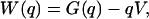 |
[1] |
where W is the potential of mean force of activation, composed of a Gibbs free-energy G(q) and a linear-voltage term. The evolution of the probability distribution p(q, t) is governed by the Smoluchowski equation, shown here in the form of a continuity equation:
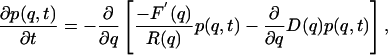 |
[2] |
where R(q) is electrical resistance and D(q) is the diffusion coefficient. R(q) and D(q) are related by the Einstein equation: R(q)D(q) = kT. We employ energy units of millielectron volts (meV), where kT = 25 meV at room temperature (17°C). The effective energy F(q) is given by F(q) = W(q) + kT ln R(q). Although a higher-dimensional characterization is possible and may be necessary for a complete description of activation (9), we limit the analysis here to a one-dimensional landscape. Solutions of Eq. 2 were obtained by discretizing the free-energy landscape (1,000–2,000 partitions) and converting the Smoluchowski equation to a master equation as described (10). Spectral decomposition of the tridiagonal rate matrix A yielded eigenvalues λ, which are decay rates of the gating current. The gating current was computed from:
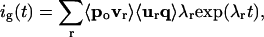 |
[3] |
where v and u are right and left eigenvectors of A, and vectors po and q contain the initial probability distribution and the gating-charge displacements, respectively. Brackets (〈〉) denote inner product. Details on sampling and filtering of fast components in Eq. 3 are given in an earlier article (10). Because the gating system obeys detailed balance, A can be symmetrized; thus, numerical routines designed for tridiagonal-symmetric matrices were used for eigenvalue analysis (11).
Results
K+ Channel Gating Currents Recorded at High-Frequency Bandwidth. A typical gating current after linear capacity subtraction recorded at a 20-kHz bandwidth is shown in Fig. 1A at 18.8°C. An early spike is detectable before the onset of the rising phase of both ON and OFF transients. To resolve the fast component of gating currents, we increased the recording bandwidth to 200 kHz. Stepping from –150 to 0 mV at 18.8°C, the time constant of decay for the fast-ON current was 7.3 μs (Fig. 1B1, trace b). During the return pulse, a mirror-image OFF component was recorded. Settling of the membrane-capacity transient was virtually complete before the decay phase of the fast-gating-current component (Fig. 1B1, trace a), demonstrating that fast-gating kinetics could be recorded accurately. The fast components of gating currents showed the same characteristics after replacing internal and external NMG+ by Cs+ or Na+, or after eliminating internal Mg2+ and external Ca2+ and adding 10 mM EGTA. Experiments performed on injected but nonexpressing control oocytes failed to produce detectable transient currents, demonstrating that fast gating is neither an artifact of the recording system, nor a property of the plasma membrane (Fig. 1B2).
Fig. 1.

Recording of gating currents at high bandwidth. (A) Fast- and slow-gating-current components for a pulse from –150 mV HP to 0 mV. The trace is 10 averages at 5 μs per point and 20 kHz, 18.8°C. (B1, a): Patch capacity transient and superimposed exponential fit(τ = 1.9 μs). Pulse from 0 to 10 mV; 10 averages at 0.5 μs per point at open bandwidth (≈350 kHz), 19.0°C; 3 nA calibration. (B1, b) Early-gating-current component and superimposed exponential fit (ON τ = 7.3 μs; OFF τ1 5.1 μs and t2 65 μs). Pulse from –150 to 50 mV with subtracting pulses from 50 mV SHP to 150 mV; 50 averages at 1 μs per point at 200 kHz, 18.8°C; 200 pA calibration. (B2) Lack of intrinsic gating currents in nonexpressing oocyte. Same recordings conditions as in B1, b. (C) Effect of changing the SHP on early gating currents recorded with a constant pulse from –100 to 0 mV and a constant 100-mV amplitude subtracting pulse; 40 averages at 0.5 μs per point and 200 kHz (10.0°C). The records and the graph show that for SHP more positive than 0 mV, the time integral of the early components reaches maximum steady value (mean ± SE, n = 4).
Subtraction of Linear-Capacity Components. The membrane capacity of native oocytes is voltage independent. It becomes voltage dependent in the voltage range of channel activation upon expressing Shaker K+ channels (8). Thus, to isolate gating currents from the linear capacity current adequately, it is necessary to determine the voltage range at which the capacity becomes voltage independent. This determination was done by applying a constant test pulse from –100 to 0 mV and shifting the SHP along the voltage axis while maintaining a constant amplitude-subtracting pulse (100 mV; Fig. 1C). The subtraction-corrected charge displacement increases with increasing SHP amplitude from –50 mV and reaches a maximal level for SHP values >0 mV, indicating that, at positive potentials, gating-charge capacitance is at the very least constant (linear domain). It is likely to be negligible as well because we could not detect negative components in the corrected fast-gating transient, such as an initial rising phase or a dip below the baseline. Barring the unlikely event of identical decay rates in test- and subtracting-gating transients, distortions such as these would be visible if a substantial amount of gating charge were subtracted. Performing similar experiments in the negative-subtracting region [traditionally SHP < –120 mV for measurements of slow-gating currents in Shaker (8, 12)], fast-gating currents were markedly distorted and the integrated-charge displacement did not reach a limiting value for SHPs as low as –300 mV (data not shown). Evidently, subtraction must be performed at positive potentials where the gating charge appears essentially immobile.
The Fast-Gating Charge Is Coupled to Channel Activation. We investigated whether the fast component was an integral component of the main gating charge, or merely an independent dielectric phenomenon energetically unrelated to the activation process. To this end, we recorded fast-OFF-gating currents for ON pulses of different durations from –100 to 50 mV. We reasoned that after the fast-ON-gating current has decayed, the shape of the fast-OFF transient should be independent of the ON-pulse duration unless fast gating is connected intimately to a slower process, such as activation. The experiment shown in Fig. 2A indicates that the decay time constant of the OFF-fast component is, in fact, not independent of the ON duration, but slows with longer pulse durations. This slowdown can be explained by the redistribution of occupancies toward states further along the activation pathway, where the fast component decays at a slower rate. These results strongly suggest that fast-charge movement is connected to the main gating-charge movement of activation that governs channel opening and closing.
Fig. 2.

Kinetic and steady state properties of gating-current early component. (A) Early and slow components of gating currents for pulses of different durations (0.1, 0.2, 0.5, and 1 ms). Pulses are from –100 to 50 mV and subtracting pulses from 50 mV SHP to 125 mV; 200 averages at 0.5 μs per point and 200 kHz, 20.0°C. Note the progressively slower relaxation and reduction in size of the OFF-gating-current early and slow components with increasing pulse durations. (B) Family of early-gating currents and superimposed ON single exponential fits (numbers at the middle) for pulses to various potentials (numbers at left) from HP –150 mV. Subtracting pulses are from 50 mV SHP to 200 mV; 400 averages at 0.5 μs per point and 100 kHz, 10.1°C. (C) QV of the early component from traces as in B by integrating 100 μs pulses in reference to the plateau at the end of the pulse, exemplified at the arrow in B for a pulse to 100 mV. Values are eo per subunit, assuming 13 eo for the limiting activation charge moved per channel with four subunits. Data are mean ± SE; n = 4. (D) Decay-rate constants as a function of the pulse potential obtained as shown in B. Data are mean ± SE; n = 4. The rate of decay is voltage independent for potentials more negative than –100 mV and becomes weakly voltage dependent for potentials more positive than –100 mV. The straight line is the fitof data points more positive than –100 mV to Aexp–(δzFV/RT), where F, R, and T are thermodynamic constants, V is voltage, A is the amplitude factor, and δz is the effective valence. The fitted δz was 0.06.
Voltage Dependence and Kinetics of the Fast Component. Although coupled to the main gating process, the fast current decays nearly three orders of magnitude more quickly; this rate of decay allows us as a first approximation to analyze it independently of slow gating. Frauenfelder (13) proposed that separation of time scales in protein kinetics occurs because of distinct tiers in activation-barrier heights. The fast-gating process may represent rapid relaxation within the earliest state of channel activation, preceding larger-scale barrier hops into adjacent states. To characterize the energy landscape W1(q) of this initial state, we recorded fast transients from a HP of –150 mV by using 100-μs test potentials in the range of –380 to 100 mV (Fig. 2B). These determinations were performed at 10°C to better separate fast and slow components, because the slow-gating-charge component has higher temperature dependence (see next section and ref. 14). The traces were fit to a single exponential decay. From these measurements, we plotted the integral [charge–voltage (QV) plot; Fig. 2C] and decay rate (Fig. 2D) of the fast component of ig. The QV plot is a quasi-equilibrium measure of the mean gating-charge displacement as a function of voltage. It was normalized to the level of a single-channel subunit by recording the full activation charge (Fig. 1A) and using the value of 3.25 eo for the activation charge moved per channel subunit (15).
For voltage steps in the negative direction (–160 to –380 mV), both the time constant of fast decay (τ) and the capacitance (C = Δq/ΔV) were essentially voltage independent (Fig. 2 C and D). The simplest process consistent with this behavior is Brownian motion in a parabolic (harmonic) well with curvature a1 (10). Over-damped harmonic kinetics predicts τ = R1/a1 and C = a1–1, resulting in a1 = 2 × 10³ meV/eo2 and a value for the resistance R1 = 25 mVms/eo. Because wells are bounded, we truncated W1(q) outside a range q– to q+ (Fig. 4A). An estimated lower limit of 0.9 eo for (q+ –q–) was required to maintain the Gaussian shape of the probability and, hence, the linearity of QV, over the measured voltage range.
Fig. 4.

Free-energy landscape model W(q) of a single subunit at V = 0 mV. (A) Detail of early activation pathway, with shading representing the standard deviation in barrier heights of the ``rough'' potential w(q). Symbols are the same as defined in the text. (B) Global gating model of a single subunit that includes slow gating barriers and the final ``open'' state on the right side (cooperativity with other subunits are neglected here). The energy landscape is depicted for –300, –150, and 0 mV, with the equilibrium-probability distribution in dots. For visualization purposes, the landscape at 0 mV was displaced downward. Note the Gaussian drift evident for negative potentials and the severe confinement within the open state at 0 mV that allows effective subtraction. The plot at the bottom shows the contribution of the resistance to the ``effective potential'' (Eq. 1). (C) Calculated ON and OFF gating currents for a 200-μs test pulse of V = –400 to 100 mV, every 10 mV, with HP = –150 mV and a 200-kHz bandwidth. (D) Plot of dominant pair of eigencomponents that contribute to the fast-gating current (triangles), with weighted mean (filled squares) superimposed onto experimental-decay rates (empty squares with standard error bars, n = 4; Fig. 2D). (E) Global QV with shading representing the standard deviation in gating-charge displacement. The dotted line is the experimental fast-gating QV.
Voltage steps to more positive potentials (–140–100 mV) revealed very different behavior. The charge displacement of the fast component as a function of voltage began to level off (Fig. 2C). This deviation from linearity could be explained either by using a reflecting barrier at q+ that compresses the Gaussian envelope of p(q,∞), or by underestimating the integral of the fast-gating current that was measured by using the initial part of the slow component as a reference (Fig. 2B, arrow). This underestimation can be due to the presence of a sloping baseline introduced by the ``rising phase'' of the slow component (Fig. 1 A). In the case of a reflecting barrier, one expects an increase in the effective rate constant k = τ–1, as p(q, t) decelerates rapidly on contact with a steep rise in potential. We found that the opposite is true; the rate of decay is slowed down with roughly exponential dependence on voltage (Fig. 2D). The most likely explanation of the apparent saturation of the fast component is, thus, an underestimation of its charge displacement because of the more prominent slow component at positive potentials. Furthermore, the slowing of the decay rate with roughly exponential voltage dependence is a property of barrier transitions; it suggests that a transition is possible out of the first well, W1, in the direction that proceeds toward activation (in the forward direction of charge movement).
Small Temperature Dependence of Early-Gating-Current Components. To gain insight into the physical process that underlies charge distribution during the early-gating current, we characterized the energetics of activation by using temperature studies. We determined the Q10 of fast-transient decay, defined as the factor increase in decay rate for a temperature change of 10°C. Fig. 3A shows that the early-gating-current component has relatively little temperature dependence. Its decay-time constant for a voltage step to 0 mV increased from 9.9 μs to 12.7 μs for a temperature decrease from 18.5 to 2.7°C. In comparison, the main slow component of gating-charge movement is quite temperature dependent (14). This temperature dependence is evident from the prominent rise in the ``baseline'' of the ON-gating current at 18.5°C compared with 2.7°C, and the increase in slow-OFF charge after a 0.5-ms test pulse. Fig. 3B shows the plot of the early rate of decay of the fast ig for negative (□) and positive (▪) pulses vs. the inverse of the absolute temperature. Stepping the voltage in the negative direction (–100 to –200 mV) revealed a modest temperature dependence of the primary component of the early transient (Q10 = 1.28 ± 0.05, n = 8). The fast component displayed a somewhat larger temperature dependence at 0 mV (Q10 = 1.46 ± 0.07, n = 9).
Fig. 3.

Temperature dependence of gating-current early component. (A) Early component recorded at 2.7°C (upper trace) and 18.5°C (lower trace). Pulses from –150 to 0 mV and subtracting pulses from 50 mV SHP to 200 mV; 100 averages at 0.5 μs per point and 200 kHz. (B) Plot of early component rate of decay as a function of the inverse of the absolute temperature in K (1/T) for pulses from –150to0mV(□) and from –100 to –200 mV (□). Data were fitted to exp–(E/kT), where E is the activation energy in meV, k = 0.086173857 meV/K, and T is the absolute temperature in K. E was 120 and 173 meV for negative and positive pulses, respectively.
Discussion
We modeled the fast-gating current by treating the voltage sensor as a Brownian-motion particle in a one-dimensional activation landscape. The model is shown in Fig. 4A; it consists of a harmonic well (W1) separated from a narrower well (W2) by a modest-energy barrier whose transition state is indicated by q*. To the right of these two wells are additional, larger barriers that determine the slower, main component of gating (Fig. 4B). The extended model in Fig. 4B that was used for fitting is a hybrid between the early-gating landscape from a single-channel subunit and the concerted transition leading to channel opening at the end of the activation pathway. It produces a rough facsimile of slow gating, which is necessary to reproduce the ``background'' on which the fast-gating current is superimposed. For the remainder of this section, we will discuss how the voltage and temperature dependence of the fast-gating current led to constraints placed on the early landscape of activation (W1 and W2).
We simulated the temperature dependence of diffusion gating within W1 by adding a rapidly varying potential w(q) to the smooth profile of W1(q). We used a statistically ``rough'' function for w(q) that has a Gaussian-distributed amplitude with standard deviation ε. For this choice of landscape, an underlying ``intrinsic'' resistance Ro can be defined that is related to the previously determined course-grained value of R1 through the equation R1 = Ro exp(ε/kT)2 (16). Fits to the temperature data at –200 mV, where gating is diffusive, yielded the values ε = 47 meV and Ro = 0.61 mVms/eo. By allowing ε to vary in other regions of the landscape while holding Ro fixed, we could effectively obtain a position-dependent resistance R(q) with a minimum value of Ro.
Analyzing the temperature data at 0 mV requires a reaction-rate theory, such as Kramers' large-friction theory, to characterize the transition barrier between W1 and W2. The effective rate constant for a single barrier system is given by k = α + β, in which α and β are unimolecular-rate constants in the forward and backward directions. The negative slope of ln(k) vs. V for potentials between –150 and 100 mV (Fig. 2D) indicates that β >> α in this voltage range. We used the following expression for the backward rate:
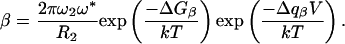 |
[4] |
The preexponential factor is Kramers' expression for a piecewise harmonic-energy profile: 2πω2ω*/R2, where ω2 and ω* are frequency terms related to the curvature a = W″ (q) and the activation barrier, respectively, through ω = a1/2/2π. The Gibbs energy of activation ΔGβ was separated into enthalpic and entropic contributions: ΔGβ = ΔHβ – TΔSβ. Plotting ln(β) vs. V yields a straight line with slope –Δqβ/kT. A least-square fit to the data in Fig. 2D yielded Δqβ = 0.06 eo. We interpreted Δqβ to be the half-width of well W2. ΔHβ was assigned the value of the activation energy 260 meV obtained from the temperature analysis at 0 mV.
By using the experimentally derived values of Δqβ, ΔHβ, a1, and R1 and assuming the landscape to be locally parabolic in the regions of the well and barrier, we adjusted the free parameters a2, a*, and R2, and the position of q* to fit the voltage dependence of k (Fig. 2D) to the model. It is evident from studying Eq. 4 that for large values of R2, the terrain leading up to the transition barrier must be relatively broad (a2 and a* are small) and/or shallow (low ΔGβ) to avoid reducing the rate constant. We found that a value of R2 = R1 was too large to construct a geometry that placed enough probability density in W2 to give weight to the W2 → W1 transition. By allowing for a variable resistance R(q) to decrease from R1 to Ro just before the W2 → W1 transition barrier (i.e., R2 = Ro; see Fig. 4B, bottom graph), we were able make W2 deeper (ΔGβ = 152 vs. 36 meV). A family of gating currents from a HP of –150 mV was calculated for the global model at a 200 kHz bandwidth (Fig. 4C). The two dominant fast eigenvalues of the rate matrix as a function of V are shown in Fig. 4D. An equivalent single-exponential decay rate k was obtained by averaging the eigen-values λr weighted by the displaced charge qr = 〈povr〉〈vrq〉. Values of k(V) adequately reproduced the plateau in fast-decay rates recorded for V < –150 mV and the exponential decay observed for V > –150 mV that is due to barrier hopping (Fig. 4D).
A distinct feature of the fast-gating model is the drop in resistance before the W1 → W2 transition state. A possible physical explanation is that the W1 → W2 transition represents charged gating residues moving from the solvent phase to an internal binding site. Thus, the value of R2 that governs the reverse W2 → W1 transition is the internal resistance of the protein Ro, which is less affected by solvent interactions. The rough potential w(q) responsible for the large value of R1 in W1 might be due to rapidly fluctuating interactions between solvent and exposed residues. The increase in friction damping that occurs with solvent exposure has been termed slaving (17).
Having obtained values of ΔGβ and ΔHβ, we were able to estimate ΔSβ, the entropy of activation for the W2 → W1 transition. Despite reducing R(q) from R1 to Ro in W2, ΔSβ has a positive value (TΔSβ = 108 meV); thus, the entropic component reduces the energy barrier by 40% at 0 mV. The positive value of ΔSβ indicates a relative disorder in the transition state q* compared with when the voltage sensor is in W2. The entropy increase likely reflects the exchange of packing interactions that occurs as the channel changes conformation, but it might in part be the consequence of a more global phenomenon of entropy decrease in the direction of channel activation. Previous work on the sodium channel (18) as well as Shaker (14) has revealed a significant decrease in the entropy in the last (opening) step of activation; this decrease in entropy suggests that pore conduction requires a structured protein matrix. A rigid open state is also indirectly supported by the insensitivity of the fast-gating current to the value of the SHP beyond 0 mV. Consequently, the open state in which we perform the subtraction protocol must be quite deep and narrow compared with W1, minimizing the movement of gating charge at positive potentials (Fig. 4B). The global equilibrium QV and its standard deviation taken from the model subunit (Fig. 4E, solid line and shaded areas, respectively) demonstrate the marked immobilization of gating charge in the open-equivalent state (V > 0 mV). One observes a plateau with very little charge fluctuation. This contrasts with the gradual creep of charge and larger fluctuations at potentials <–150 mV when the channel is primarily in state W1.
Conclusions
Gating currents in Shaker possess a fast component that precedes the main charge movement. We modeled fast gating as the movement of a voltage sensor that fluctuates within a broad harmonic well, W1, but that also makes frequent transitions to a narrower well, W2. A plausible physical interpretation of this process consists of a rapid equilibrium by charged residues between the intracellular aqueous phase (W1) and an internal binding site (W2). These fast dynamics precede the main trans-location of gating charge to the extracellular phase that constitutes slow gating. Some characteristics of the gating pathway, such as the narrowing and deepening of the open state and the decrease in resistance and entropy, point to a structuring of the channel as it activates. Testing this idea will probably require more than the eventual elucidation of the crystal structure of a voltage-gating channel because, by the very nature of the technique, it can only confirm what we already suspect: that the open inactivated state of the channel is well ordered. If this suspicion proves to be the case, further dynamical studies, such as site-directed spectroscopy, will be required in addition to the open-channel structure to develop a complete understanding of ion-channel gating.
Acknowledgments
This work was supported by National Institutes of Health Grants GM52203 (to E.S.) and GM30376 (to F.B.). This paper is dedicated to the memory of Marcela, daughter of E.S.
Abbreviations: HP, holding potential; meV, millielectron volts; NMG, N-methylglucammonium; QV, charge–voltage; SHP, subtracting holding potential; V, applied voltage.
Note Added in Proof. Prior to publication of this article, the crystal structure of a voltage-dependent bacterial K+ channel was made available (19). The authors state that the channel exhibits considerable conformational flexibility that required antibody stabilization to form crystals, in keeping with our view of a relatively unstructured channel at negative potentials. An interesting source of future speculation is why, if the channel is structurally rigid in the open state, as we argue here, crystallization could not be induced in the absence of stabilizing factors.
References
- 1.Doyle, D. A., Morais, C. J., Pfuetzner, R. A., Kuo, A., Gulbis, J. M., Cohen, S. L., Chait, B. T. & MacKinnon, R. (1998) Science 280, 69–77. [DOI] [PubMed] [Google Scholar]
- 2.Zhou, Y., Morais-Cabral, J. H., Kaufman, A. & MacKinnon, R. (2001) Nature 414, 43–48. [DOI] [PubMed] [Google Scholar]
- 3.Allen, T. W. & Chung, S. H. (2001) Biochim. Biophys. Acta 1515, 83–91. [DOI] [PubMed] [Google Scholar]
- 4.Berneche, S. & Roux, B. (2001) Nature 414, 73–77. [DOI] [PubMed] [Google Scholar]
- 5.Bezanilla, F. (2000) Physiol. Rev. 80, 555–592. [DOI] [PubMed] [Google Scholar]
- 6.Forster, I. C. & Greeff, N. G. (1992) Eur. Biophys. J. 21, 99–116. [DOI] [PubMed] [Google Scholar]
- 7.Perozo, E., MacKinnon, R., Bezanilla, F. & Stefani, E. (1993) Neuron 11, 353–358. [DOI] [PubMed] [Google Scholar]
- 8.Stefani, E., Toro, L., Perozo, E. & Bezanilla, F. (1994) Biophys. J. 66, 996–1010. [DOI] [PMC free article] [PubMed] [Google Scholar]
- 9.Sigg, D. & Bezanilla, F. (2003) Biophys. J. 84, 3703–3716. [DOI] [PMC free article] [PubMed] [Google Scholar]
- 10.Sigg, D., Qian, H. & Bezanilla, F. (1999) Biophys. J. 76, 782–803. [DOI] [PMC free article] [PubMed] [Google Scholar]
- 11.Press, W., Teukolsky, S., Vetterling, W. & Flannery, B. (1992) Numerical Recipes in C (Cambridge Univ. Press, New York).
- 12.Bezanilla, F., Perozo, E., Papazian, D. M. & Stefani, E. (1991) Science 254, 679–683. [DOI] [PubMed] [Google Scholar]
- 13.Frauenfelder, H., Sligar, S. & Wolynes, P. G. (1991) Science 254, 1598–1603. [DOI] [PubMed] [Google Scholar]
- 14.Rodriguez, B. M., Sigg, D. & Bezanilla, F. (1998) J. Gen. Physiol. 112, 223–242. [DOI] [PMC free article] [PubMed] [Google Scholar]
- 15.Schoppa, N. E., McCormack, K., Tanouye, M. A. & Sigworth, F. J. (1992) Science 255, 1712–1715. [DOI] [PubMed] [Google Scholar]
- 16.Zwanzig, R. (1988) Proc. Natl. Acad. Sci. USA 85, 2029–2030. [DOI] [PMC free article] [PubMed] [Google Scholar]
- 17.Fenimore, P. W., Frauenfelder, H., McMahon, B. H. & Parak, F. G. (2002) Proc. Natl. Acad. Sci. USA 99, 16047–16051. [DOI] [PMC free article] [PubMed] [Google Scholar]
- 18.Correa, A. M., Bezanilla, F. & Latorre, R. (1992) Biophys. J. 61, 1332–1352. [DOI] [PMC free article] [PubMed] [Google Scholar]
- 19.Jiang, Y., Lee, A., Chen, J., Ruta, V., Cadene, M., Chait, B. T. & MacKinnon, R. (2003) Nature 423, 33–41. [DOI] [PubMed] [Google Scholar]