

Abstract
Current approaches to 3D imaging at subcellular resolution using confocal microscopy and electron tomography, while powerful, are limited to relatively thin and transparent specimens. Here we report on the use of a new generation of dual beam electron microscopes capable of site-specific imaging of the interior of cellular and tissue specimens at spatial resolutions about an order of magnitude better than those currently achieved with optical microscopy. The principle of imaging is based on using a focused ion beam to create a cut at a designated site in the specimen, followed by viewing the newly generated surface with a scanning electron beam. Iteration of these two steps several times thus results in the generation of a series of surface maps of the specimen at regularly spaced intervals, which can be converted into a three-dimensional map of the specimen. We have explored the potential of this sequential “slice-and-view” strategy for site-specific 3D imaging of frozen yeast cells and tumor tissue, and establish that this approach can identify the locations of intracellular features such as the 100 nm-wide yeast nuclear pore complex. We also show that 200 nm thick sections can be generated in situ by “milling” of resin-embedded specimens using the ion beam, providing a valuable alternative to manual sectioning of cells and tissues using an ultramicrotome. Our results demonstrate that dual beam imaging is a powerful new tool for cellular and subcellular imaging in 3D for both basic biomedical and clinical applications.
Keywords: 3D cellular imaging, Cryo-electron microscopy, Dual beam imaging, Focused ion beam, Yeast, Tumor tissue
1. Introduction
Emerging methods in biological electron microscopy afford new and exciting prospects to study the three-dimensional architectures of protein complexes, cellular machines, whole cells, and even slices of tissue at an unprecedented resolution. A number of powerful approaches have been developed and applied to explore structure–function relationships in macromolecular assem- blies spanning a wide range of sizes (Subramaniam and Milne, 2004). In particular, methods such as electron tomography are now at a stage where they can bridge a critical imaging gap between cellular structure and protein structure (Forster et al., 2005; Marsh et al., 2004; McIntosh et al., 2005; Subramaniam, 2005; Zhang et al., 2005).
Current methods for ultrastructural analysis of tissues at subcellular resolution generally rely on imaging using either light or electron microscope modes of imaging. Conventional optical imaging is limited in practice to resolutions of about 0.1 μm in the very best cases, and to about 1 μm in most routine imaging applications. Electron microscopy is typically used for imaging at higher resolution, but this requires two important steps which require manual input: preparation of the specimen by fixation and embedding, followed by sectioning using an ultramicrotome, and imaging in a transmission electron microscope. When this works successfully, it is possible to record projection images or tomographic image series of cells and tissues that are at higher resolution than achiev- able by optical microscopy. The increased resolution, however, comes at the expense of considerably lower speeds in sample preparation and data collection. This is particularly a concern when serial sectioning is considered for the generation of 3D datasets. Subcellular electron microscope imaging is therefore not commonly used in clinical settings, even though the type of information that can be obtained such as antigen localization, visualization of organelle degeneration, or location of pathogens is potentially very useful.
Our approach to 3D imaging (Fig. 1) with a dual beam microscope is based on using a focused ion beam to create a cut at a designated site in the specimen, followed by viewing the newly generated surface with a scanning electron beam. Iteration of these two steps several times results in the generation of a series of surface maps of the specimen at regularly spaced intervals. A series of surface maps can then be computationally assembled into a volume represen- tation of a specimen. The focused ion beam allows the removal of material from the surface of the specimen in increments as small as about 20 nm, and greater than 100 μm in width. A unique feature of dual beam imaging that is especially valuable for complex and heterogeneous biological specimens is the ability to explore 3D structure at any chosen site in bulk samples such as cell pellets and tissue blocks. Instruments with this “slice-and-view” capability are available commercially, and have been used extensively to view the internal architecture of semiconductors and other solids (Giannuzzi et al., 2002; Giannuzzi and Stevie, 2005; Sugiyama and Sigesato, 2004). Preliminary efforts of the use of focused ion beam microscopy to view the internal structure of biological specimens have also been reported (Ballerini et al., 2001; Drobne et al., 2005; Gestmann et al., 2004; Heymann et al., 2005; Mulders, 2003; Young et al., 1993). Here, we report on our progress in applying dual beam imaging to biologically relevant samples at room temperature and at cryogenic temperatures. In addition, we demonstrate the potential of using focused ion beam milling to site-specifically generate thin sections and cylindrically shaped specimens by “in situ lift out” (Giannuzzi et al., 2002) that can be subsequently imaged at higher resolution in 2D or in 3D using a transmission electron microscope.
Fig. 1.

Schematic depicting the principle of focused ion beam milling and scanning electron microscope imaging in a dual beam electron microscope. The ion source (red, left) and the electron source (blue, top) are arranged at an angle allowing the ion beam (Ga+) to remove material from the surface of the specimen (yellow) such that it can be imaged by the scanning electron beam (e−). As a result, a trench is generated, thus enabling imaging of the interior of the specimen. As shown, the exposed surface is parallel to the plane of the ion beam, and at an angle of 52 ± 2° to the electron beam.
2. Materials and methods
2.1. Preparation of critical point-dried and plastic-embedded yeast specimens
Yeast cells (strain W303) (Wallis et al., 1989) were grown in YPD medium (2% yeast extract, 1% peptone, and 2% glucose) to mid-log phase and then collected by centrifugation. Cell pellets were processed essentially as described in Bauer et al. (2001) where the cell wall of yeast is partially removed by enzymatic treatment to facilitate fixation (using glutaraldehyde) and contrast enhancement (using osmium tetroxide). Specimens were dehydrated with a graded series of acetone–water mixtures and then subjected to critical point-drying. Critical point-dried specimens were mounted and coated with platinum prior to focused ion beam milling.
For plastic embedding, yeast cells pellets were either fixed and treated with osmium tetroxide as described above (as in the specimen used for recording images shown in Fig. 6) or fixed in 2.5% glutaraldehyde in 0.1 M cacodylate buffer (pH 7.0) for 2 h at 4 °C, then washed and incubated with 1% aqueous sodium metaperiodate for 15 min at room temperature (as in the specimen used for recording images shown in Figs. 2A and B). After several washes with water, the pellet was incubated in 0.1% aqueous uranyl acetate over night. Following removal of excess uranyl acetate, the specimens were dehydrated in a graded series of ethanol–water mixtures, followed by one wash in dry acetone and then progressively infiltrated with Spurr's resin. After polymerization, sections of about 100 nm thickness were prepared using a Leica UCT ultramicrotome (Leica Microsytems, Vienna, Austria), collected on carbon-coated 200 mesh electron microscope grids, and stained for 15 min with 4% aqueous uranyl acetate, followed by staining for 2 min with 1 mM lead citrate.
Fig. 6.

Preparation of specimen with cylindrical geometry by focused ion beam milling. (A) A scanning electron microscope image of a precursor to the final cylindrical specimen (B) that was obtained by focused ion beam milling from a slab of resin containing chemically fixed yeast cells. The outline of an individual yeast cell is visible within the specimen as an oval area of high contrast. A platinum layer is present on the top of the precursor that is mounted to a copper support grid visible at the bottom. (B) The final needle-like specimen is seen. (C) A transmission electron microscope image of the specimen shown in (B); at the top of the needle, the remaining layer of platinum is visible; within the needle, lighter areas represent the resin matrix while dark, oval areas originate from yeast cells embedded in the matrix. The copper support is visible at the bottom. Inset (C), a projection image of a subvolume from a single yeast cell is shown at higher magnification. Scanning electron microscope images were collected using a Nova 600 NanoLab microscope operating at 5 kV and transmission electron microscope images were collected using a Sphera G2 microscope operating at 200 kV. Scale bars: (A–C), 2 μm, insets, 0.5 μm.
Fig. 2.

2D and 3D imaging of yeast cells by scanning electron microscopy. Scanning images of cross-sections of plastic-embedded (A and B) and critical point-dried yeast cells (C and D) at low (A and C) and high (B and D) magnification. Resin surface (A) and yeast pellet surface (B) were coated with platinum (white) prior focused ion beam milling. The long white arrows point to the location of the nuclear membrane in the budding yeast cells shown in (B and D), and the short white arrows point to the locations of the vacuoles, which appear black in (A and B) and white in (C and D). (E) 3D visualization of critical point-dried yeast cells was accomplished by iterative focused ion beam milling and scanning electron microscope imaging: segmented rendering of 3D volume displaying cell wall (gray envelope), the vacuolar region (green), and the nucleus (blue) of an individual, budding yeast cell. Rendering was done using the Amira software package (Mercury Computer Systems GmbH, Berlin, Germany). The images in (A and B) were collected using a Strata 400 dual beam microscope, the images in (C and D) using a Nova 600 NanoLab dual beam microscope. Scale bars: (A and C) 10 μm, (B) 2 μm, (D) 0.5 μm.
2.2. Preparation of yeast cells for imaging at cryogenic temperatures
Fresh Bakers yeast (Burns Phil Food, Fenton, MO) was re-suspended in standard yeast extract, peptone medium and cultured at about 25 °C for 2 h with agitation. From this culture, 1 ml of cells was collected and the resulting pellet was re-suspended in the culture medium supplemented with 4% glucose. Cells were collected by centrifugation after an additional hour of incubation. From the soft pellet, cells were spread on a scanning electron microscope specimen stub and frozen by plunging into liquid nitrogen. Cryo-transfer was achieved using either an Alto system (Oxford Instruments, Oxon, UK) as in our earlier experiments with plunge-frozen yeast specimens, or using a Polaron PP2000T (Quorum Technologies, Newhaven, UK) system used for most of the experiments described here. In each case, the specimen stub was first inserted into a chamber where the samples were fractured and coated with platinum and palladium. Subsequently, the stub was transferred into the chamber of a NOVA 600 NanoLab DualBeam instrument (FEI Company, Hillsboro, OR). The specimens were then processed and imaged as described in the section on dual beam cryomicroscopy. Unless stated otherwise, all scanning electron images were based on the detection of secondary electrons.
2.3. Preparation of tissue specimens
Lymphoid tumor tissue was kindly provided by Dr. Pete Choyke (National Cancer Institute, NIH, Bethesda, MD). Thin pieces of glutaraldehyde-fixed tissue specimens were mounted on a specimen stub and rapidly frozen by plunging them into liquid nitrogen. After delivery into the cryotransfer system, the specimens were coated at −140 °C with platinum–palladium for 30 s to yield a metal layer of ∼3 nm thickness. For imaging and preparation of thin sections for transmission electron microscopy at room temperature, specimen cubes ∼2 mm long were excised from the tissue and incubated for 48 h in 2.5% glutaraldehyde in 0.1 M cacodylate buffer (pH 7.2) at 4 °C. Fixed specimens were washed in cacodylate buffer, exposed to 1% aqueous osmium tetroxide for 1 h at room temperature, extensively rinsed with water, subjected to dehydration using a graded series of ethanol–water mixtures followed by one wash in dry acetone, and finally, embedded in Epon. Sections were prepared and processed as described above for the yeast specimens.
2.4. Dual beam microscopy at room temperature
For dual beam microscopy of plastic-embedded specimens, the tops of resin blocks from BEEM capsules (EMS, Hatfield, PA) were trimmed to a pyramidal shape using a razor blade with block faces typically of about 2mm2 in area. The surface was smoothened by sectioning using a conventional 45° diamond knife from Diatome (distributed by EMS, Hatfield, PA). Thin sections were prepared and inspected by transmission electron microscopy to confirm the presence of the desired region on the exposed block surface. The entire pyramidal block was removed and mounted with the wider base onto an SEM stub using silver paint (SPI Supplies, West Chester, PA) such that the ultramicrotome-prepared, flat surface of the resin block pointed upwards, perpendicular to the electron column. For room temperature experiments, images were recorded using either a Nova 600 NanoLab or a Strata 400 dual beam microscope. Prior to focused ion beam milling, an area of interest was selected and coated with a platinum layer ∼200 nm thick using the gas injector needle in the main specimen chamber. Imaging and focused ion beam milling of the specimen was done as described below.
2.5. Dual beam microscopy at cryogenic temperatures
For all experiments carried out at cryogenic temperatures, we used a Nova 600 NanoLab dual beam instrument (FEI, Hillsboro, OR), equipped with a gallium ion source for milling and a field emission gun scanning electron microscope with an in-lens secondary electron detector for imaging. The cryo-transfer system was mounted on one of the access ports, and used to maintain the specimen at temperatures of −140 °C. For focused ion beam milling, the specimen stage was tilted to 52° and exposed to the focused ion beam. A cross sectional cut was introduced in two stages. First, a coarse cut was made at high beam currents (typically ∼3 nA) and at an accelerating voltage of 30 kV to create a trench that enabled viewing of the cross-section (see Fig. 1). Usually, 50–150 μm wide trenches were cut into the specimen. In the second step, the specimen was tilted to 54°, and the ion beam was scanned using a lower ion beam current (typically ∼500 pA) to polish and smoothen the surface. In some experiments, the interior of thick cell or tissue specimens was first exposed by freeze-fracturing before ion beam milling. The exposed surface was coated with a platinum–palladium layer and then transferred through a vacuum valve system to the main specimen chamber, where it was maintained at ≤−140 °C by purging the cryo-stage with nitrogen gas generated from a liquid nitrogen source. A metal plate placed close to the specimen, whose temperature was held between −170 and −185 °C, served as an anti-contaminator by reducing the extent of ice deposition on the cold specimen. The device also assisted in the sublimation of water from the specimen surface when the sample was transiently heated from −140 to about −90 °C by reducing the nitrogen gas flow to the cryo-stage. At the desired point of sublimation, the process was stopped by rapidly cooling the specimen back to −140 °C. Secondary electron scanning electron microscope images were typically recorded at accelerating voltages of 3 kV and at a beam current of 68 pA in the immersion lens mode. For slice-and-view images series, a step size of about 100 nm was chosen for the removal of material from the specimen surface using the focused ion beam.
2.6. Preparation of thin sections by focused ion beam milling
This “in situ-lift-out” method we have employed here is commonly used to prepare samples from inorganic materials for transmission electron microscopy (Giannuzzi et al., 2002). To make sections from resin-embedded cell or tissue blocks, cuts were first made on both sides of the desired location to leave behind a thin slab. A fine sample needle from Omniprobe (Dallas, TX) mounted to an access port of the Nova 600 NanoLab was attached to the sample block by deposition of platinum at the junction using a gas injection system. The interaction of the scanning ion beam with the gas causes the deposition of a small amount of material, by chemical vapor deposition, at the junction between the Omniprobe needle and the specimen. This process allows “nano-welding” of the needle with the specimen slab, and permits manipulation of the specimen by moving the other end of the needle. After removal of the slab from the block, it was mounted on a special lift-out grid, a half-grid (Omniprobe), by nano-welding as above, and milled down to the desired thickness with the ion beam. The half-grid used was made of copper with solid bars protruding from the grid edge to its center thus permitting the “lift-out” sections to be attached to the edges of the bars. The attached sections were then subjected to further focused ion beam milling to reduce the thickness to the desired value for analysis by transmission electron microscopy (see Fig. 6B). Transmission electron microscope images were recorded either on a Tecnai 12 microscope operating at 120 kV, or on a Tecnai F30 microscope operating at 300 kV (both FEI, Hillsboro, OR) using a 2k × 2k CCD camera (Gatan, Pleasanton, CA).
2.7. Tomography of sections generated by focused ion beam milling
For tomography, the plastic section tethered to the half grid was further stained with uranyl acetate and lead citrate, and decorated with 15 nm gold-particles. It was then loaded onto a Model 916 high-tilt holder (Gatan, Pleasanton, CA) and imaged at 12 000× magnification using a Tecnai F30 transmission electron microscope (FEI, Hillsboro, OR) operating at 300 kV. Images were recorded using a Gatan Ultrascan 2k × 2k CCD camera in conjunction with the FEI tomography software suite, and filtered images were generated and processed as previously described (Zhang et al., 2005) using the IMOD software suite (Kremer et al., 1996).
2.8. Preparation of cylindrically shaped specimens by ion beam milling
For preparation of cylindrically shaped specimens of plastic-embedded yeast cells, the area targeted for milling was first coated with a layer of platinum ∼2 μm thickness. Then, a wedge-shaped slice was generated by milling with the focused ion beam, and the slice was subsequently transferred to a half-grid using the Omniprobe nanomanipulator as described in the previous section. From the slice, an approximately square block surface was generated and milled in concentric circles by applying a focused ion beam with an area defined by an inner and an outer diameter. Progressive decrease of the diameter and the beam current allowed the controlled removal of material. Transmission electron images of the final product were recorded on a Tecnai Sphera G2 microscope equipped with a LaB6 filament operating at 200 kV (FEI, Hillsboro, OR) using a 2k × 2k CCD camera (Gatan, Pleasanton, CA). Contrast in the TEM images is mainly the result of exposure of the cells to uranyl acetate prior to embedding in resin.
3. Results
3.1. 3D imaging of critical point-dried yeast cells
Images recorded from yeast cells at room temperature are presented in Fig. 2 for resin-embedded specimens (Figs. 2A and B) or critical point-dried specimens (Figs. 2C and D). In the low magnification images (Figs. 2A and C), the rectangular trench produced by the focused ion beam can be seen. In the resin matrix (Fig. 2A), yeast cells have a round to oval shape, occasionally showing protrusions indicating bud-formation as seen in Fig. 2B. The cell is enveloped by its cell wall that is delineated on the exterior and interior by a faint white line. Within the majority of cells, darker areas representing the nucleus and vacuole are visible. The white arrow in Fig. 2B indicates the boundary between the nucleus and the cytoplasm with the darker area representing the nucleus. The relief-like appearance of the cell in Fig. 2A is the result of charge build-up on the resin surface during initial milling at higher beam currents; this disappears as milling is continued at lower currents producing a smooth, polished surface as shown in Fig. 2B.
Inside the trench of critical point-dried yeast cells (Fig. 2C), cross-sections of individual yeast cells appear as gray circular regions enclosed by a white (i.e., high-contrast) region composed of an ion beam-induced deposit of platinum. At the bottom of the trench, needle-like features are visible that are the result of topography generated during the process of focused ion beam milling at high beam currents. These features are artifacts of focused ion beam milling and can be observed after the initial stage of excavation. A higher magnification view of a cell in the process of division is shown in the Fig. 2D. The region with high contrast in the “mother” cell indicates the presence of the vacuole that occupies a significant fraction of the internal space of the yeast cell. The faint white band that extends to the right of the vacuolar region represents the cross-section of the membrane that encloses the nucleus. Other features that are less prominent and cannot be easily interpreted are also present throughout the cell body.
While the overall morphology of the yeast cells in the two preparations is similar, the most noticeable difference is observed in the vacuolar regions. Specimen preservation in the chemically fixed, resin-embedded cells is considerably superior to that observed in the critical point-dried cells, which were subjected to a much harsher drying step. Since no internal vacuolar structures are observed in the resinembedded cells, we conclude that the high contrast is an artifact solely arising from the critical point-drying procedure, and not an internal feature of the vacuolar regions. A series of images such as the one shown in Fig. 2D was recorded by iteration of focused ion beam milling and scanning electron microscope imaging (presented as movie #1 in supplementary material). Each successive milling step removed a slice with a thickness of approximately 100 nm. The resulting stack of images, which represents a discrete sampling of the 3D structure of the yeast cell, was used to generate a volume representation of the yeast cell highlighting the 3D structure of prominent cellular components such as the outer cell membrane, the vacuolar region and the nucleus (Fig. 2E). The time taken to generate ∼100 progressive surface images at a step size of 100 nm while excavating a volume of ∼50 μm width, ∼20 μm height, and ∼10 μm depth, was about 2h.
3.2. Imaging of plunge-frozen yeast cells
The contrast visible in the images recorded from the critical point-dried and plastic-embedded cells reflects the distribution of the stain (osmium and uranyl acetate) rather than intrinsic contrast of cellular material. For visualizing structural details in unstained cells and tissues, we maintained the specimen at temperatures at ≤−140 °C by using a cryogenic specimen transfer system. Fig. 3 presents results from dual beam imaging of frozen yeast cells which expands on the preliminary results reported in Mulders (2003). Fig. 3A shows a scanning electron microscope image of the interior of a rapidly frozen, unstained pellet of yeast cells. In cross-section, the yeast cells appear as gray ovals or circles with low internal contrast but sharp outlines. One approach to enhance contrast is to locally sublime the ice present at the surface by transiently raising the temperature of the specimen. This procedure enhances the contrast leading to a sharpening of membrane features (Fig. 3B). A greater increase in contrast is observed with surface coating of the specimen with platinum, (Fig. 3C), and in the expanded view of one of the cells as shown in Fig. 3D. Prominent features that are visible include the cell wall that is sharply delineated from the surrounding matrix, the nucleus, and vesicle-like entities that are present throughout the cell body. The white arrow points to the location of a pore in the nuclear membrane with approximate dimensions of about 100 nm. For comparison, a scanning electron microscope image of a freeze-fractured yeast cell from the same preparation is shown in Fig. 3E, where the surfaces of the organelles can be visualized following their exposure by freeze-fracture. Note that in contrast to the yeast cells in the experiments presented in Fig. 2, the Baker's yeast cells in the cryo experiments were cultured under conditions where they do not form large vacuoles.
Fig. 3.

Scanning electron microscope images of yeast cells plunge-frozen in liquid nitrogen and imaged at −140°C. (A–C) Surface images generated by focused ion beam milling depicting progression in the sublimation process initiated by transiently raising the specimen temperature; (D) view of the crosssection of an individual yeast cell exposed by focused ion beam milling and contrasted by sublimation and coating with platinum and palladium. Arrow points to the location of a pore in the nuclear membrane. (E) Scanning electron microscope image of freeze-fractured, platinum–palladium coated yeast cells. Arrow indicates location of nuclear pore. Scale bars: 2 μm. A subset of the data presented in this figure (C and D) was presented in the preliminary report by Mulders (2003) on the potential of combining focused ion beam milling with scanning electron microscopy.
3.3. Visualization of lymphoid tumor tissue
In Fig. 4, we show the use of dual beam imaging to explore the interior of tissue specimens at room temperature and cryogenic temperatures. Conventional imaging of ultramicrotome-derived thin-sections of chemically fixed, plastic-embedded, post-stained lymphoid tumor tissue by transmission electron microscopy shows the expected rich detail at the cellular level (Fig. 4A). To inspect the 3D morphology of the tumor tissue within the resin, we removed a small volume from the resin block used for ultramicrotomy and mounted it for processing and imaging in the dual beam microscope. A cross-section of the plastic-embedded tumor tissue was exposed by focused ion beam milling and first visualized by scanning electron microscopy (Fig. 4B). The main features present in Fig. 4A are clearly visible in this scanning image through their contrast differences, mainly at membrane boundaries. The image in Fig. 4B is shown in inverted contrast for a more direct comparison with Fig. 4A. A successive series of slices was obtained as in the case of the yeast cells, and the series of images was combined to generate a 3D representation of a selected volume within the tumor tissue (Fig. 4C and inset) (presented as movie #2 in supplementary material). In Fig. 4D, we show scanning electron microscope images of the same tissue shown in Fig. 4, but obtained instead from glutaraldehyde-fixed, unstained lymphoid tumor tissue, plunge-frozen and imaged at −140 °C. These experiments demonstrate that intrinsic contrast of the tissue is adequate to visualize ultrastructural detail. Unlike in the case of the room temperature experiments in Figs. 4A and B, the features observed in Fig. 4D cannot easily be compared at present with transmission electron microscopic images from exactly the same region; however, the overall morphology observed is generally similar to that observed in the stained specimens. Vertical streaks observed in the images are cutting artifacts (see Section 4). We anticipate that significant improvements need to be made to the image quality with the use of better freezing protocols.
Fig. 4.

Transmission and scanning electron microscope images of chemically fixed, plastic-embedded lymphoid tumor tissue at room temperature, and chemically fixed, plunge-frozen lymphoid tumor tissue at −140 °C. (A) transmission image of a post-stained, ultramicrotome-derived thin section of lymphoid tumor tissue. (B) Scanning image showing the cross-section of an area that was exposed by focused ion beam milling from a region similar to that displayed in (A), and from the same specimen. To facilitate the comparison between (A and B), the contrast of the image in (B) has been inverted. (C) 3D visualization of lymphoid tumor tissue by iterative focused ion beam milling and scanning electron microscope imaging: a series of images such as those shown in (B) (without contrast inversion) were combined in a stack and segmented to visualize selected features (rendered in gold, magenta) of the tissue in 3D. The inset shows a 3D rendering of the central feature in the image stack segmented by density thresholding. (D) Scanning images of platinum–palladium coated lymphoid tumor tissue after focused ion beam milling, which generates a shallow trench exposing an extended cross-section of volume within the tumor tissue. Note that the contrast in (A and B) is the opposite to that of the image in this panel. Scale bars: 5 μm.
3.4. Generation of thin plastic sections by focused ion beam milling
Focused ion beam milling can also be used to generate thin sections suitable for subsequent analysis in a transmission electron microscope as shown previously for inorganic specimens. (Giannuzzi et al., 2002). We demonstrate the feasibility of this technique for biological specimens by generating a section from a block of plastic resin containing chemically fixed yeast cells. A rectangular slice of resin was excavated from the block using the focused ion beam at the region of interest (Fig. 5A). Once the slice had the desired dimensions, it was tethered to an Omniprobe sample needle by ion beam induced deposition of platinum and then excised from the block of resin (Fig. 6A). For further processing in the dual beam microscope, and for mounting in a holder for tomography, the slice was transferred to a half-grid as described under Section 2. Using the Omniprobe sample needle, the slice was attached to the half-grid (Fig. 5B) by ion deposition. Finally, the needle was released from the slice by ion milling, and focused ion beam milling was used to further reduce the thickness of the section to about 200 nm. Figs. 5C and D show the images of the lamella as observed using the scanning electron beam, and using a transmission electron microscope, respectively. The dimensions of the final lamella were about 12 μm by 16 μm by 0.2 μm. Cross-sections of two individual yeast cells are visible in the images recorded from the lamella, with internal vacuolar regions being most prominent in the projection images. In Fig. 5D, the vacuoles appear black as a result of fixation with osmium tetroxide during sample preparation. Sections such as these were stained further with uranyl acetate/lead citrate and decorated with gold particles, as shown in the expanded view of an individual yeast cell in Fig. 5E. All of the staining procedures were carried out with the section attached to the grid. A series of tilted images (ranging from −45° to +60° tilt angle) was recorded from this specimen for determination of the 3D structure of the slice by electron tomography. A single slice from this volume (nominal thickness about 1 nm) is shown in Fig. 5F. Cross-sections through some of the internal membranes can be seen in this slice. The distribution of fine darkly stained dots in the interior of the cell corresponds well with the expected size and distribution of ribosomes located in the cytoplasm.
Fig. 5.
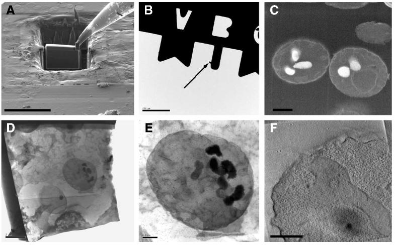
Scanning (A–C) and transmission (D–F) electron microscope images displaying the preparation, handling, and visualization of a plastic-resin section generated by focused ion beam milling at room temperature. (A) A plastic section (about 12 μm × 16 μm × 1 μm) generated by focused ion beam milling of a block of resin containing chemically fixed yeast cells. The section is tethered on the upper right corner to an Omniprobe sample needle by ion deposition. (B) The section (indicated by arrow) after attachment to a half-grid and release from the Omniprobe sample needle. A view at higher magnification is presented in (C). Prior to imaging for tomography, the section was further processed by focused ion beam milling to a lamella of about 200 nm thickness. (D and E) Transmission images of a lamella that was negatively stained and decorated with 15 nm gold particles used as fiducial markers for tomographic experiments. (F) A tomographic slice obtained from a 3D volume reconstruction of a region in the section. Each of the black dots, indicated by the white arrow, roughly corresponds to the staining of a single ribosome in the cytoplasm. The image in (B) was collected using a Tecnai 12 microscope operating at 120 kV and the images in (D–F) were collected using a Tecnai F30 microscope operating at 300 V. Scale bars: (A) 20 μm, (B) 200 μm, (C) 1μm, (D) 2 μm, (E and F) 0.5 μm.
3.5. Generation of cylindrical specimen by focused ion beam milling
A further example for preparing a specimen with a specific geometry is shown in Fig. 6. A cylindrically shaped specimen was generated by focused ion beam milling while monitoring the progress simultaneously by imaging with the scanning electron beam. The process was initiated with the excision of a slab from a resin block containing chemically fixed yeast cells followed by transfer to a copper support grid as described in the previous paragraph and in Section 2. The slab was then trimmed using the focused ion beam to yield a cylindrically shaped specimen that protrudes from the copper support grid as shown in Fig. 6A. At the top of the resin-cylinder, a layer of platinum is present and in the middle, the outline of an individual yeast cell can be seen as an oval area. This specimen was further refined by circular milling to produce the final, needle-like specimen that has a tip diameter of approximately 0.8 μm (Fig. 6B). The presence of the thick platinum layer at the top allows the shaping of the specimen to be carried out with minimal loss of the biological material. The needle is wide at its base, approximately cylindrical in the middle, and narrow at the top. The outlines of individual yeast cells appear as oval regions in the transmission electron microscope image of the needle (Fig. 6C).
4. Discussion
The challenge of imaging the interior of thick biological specimens without recourse to manual sectioning is a problem of longstanding and general interest. Because of the finite penetration depths of optical radiation and electron beams, until recently, the only approach to internal imaging has involved manual sectioning with a microtome for subsequent evaluation of the section in an optical or electron microscope. Nevertheless, some options have begun to emerge as documented in recent reports from a variety of laboratories (Denk and Horstmann, 2004; Larabell and Le Gros, 2004; Tsai et al., 2003; Weiss et al., 2000). In one approach (Tsai et al., 2003), a strong infrared laser beam is used to ablate a thin surface layer of material, which is then followed by imaging using two-photon laser scanning microscopy with a low intensity beam to visualize fluorescent probes at the exposed surface. By iterating this process, it is thus possible to record a series of images that describe the three-dimensional structure of the material at sampled at intervals of about 5–10 μm. In a second approach (Denk and Horstmann, 2004), the biological specimen is stained and embedded in a plastic block, and sectioned in a microtome that is located inside the imaging chamber of a scanning electron microscope. A scanning electron beam records the image of the block after each section has been removed, which is then used to generate a series of slices that sample the specimen at intervals of about 70 nm. Yet another approach that is currently being explored is based on soft X-ray microscopy (Larabell and Le Gros, 2004; Weiss et al., 2000) where a transmission X-ray microscope is used to collect X-ray projections of an object over a wide range of tilt angles, followed by 3D reconstruction using the same principles as in electron tomography. As noted below, our approach to 3D imaging using a dual beam microscope shares some elements in common with each of the above approaches, and provides an opportunity for further advances in resolution, speed and potential for clinical applications.
The approach to 3D imaging of cell and tissue specimens that we have implemented here provides unique possibilities that are not present in currently available single beam electron microscopes, and the other two recently described methods to serial 3D imaging discussed above. First, biological specimens can be imaged in a frozen state without the need for staining or embedding. Thus, it is possible to rapidly freeze tissue samples to vitrify them in a near-native state, and to image their interior immediately at a specified location, and at cryogenic temperatures by successive iteration of the ion and electron beams. The same specimen can also be fixed, stained or embedded in plastic resin, and subsequently imaged at room temperature for comparative analysis by dual beam microscopy and transmission electron microscopy, and to obtain additional information on 3D ultrastructure by electron tomography. Second, in-plane resolutions as high as 1 nm are theoretically achievable with a field-emission gun equipped scanning electron microscope instrument as we have used here, and it may be possible to achieve a sampling interval in the perpendicular direction as little as 20 nm. In the studies we report here, we estimate that we can detect features with spatial dimensions of about 100 nm (nuclear pore complex) and sampling intervals of about 100 nm from frozen biological specimens. The level of detail in the 3D images from yeast cells processed and imaged using dual beam microscopy is comparable to that of the recently reported X-ray tomographic studies of yeast cells (Larabell and Le Gros, 2004) at a deduced resolution of about 60 nm. We anticipate that even higher spatial resolutions and smaller sampling intervals will become possible for dual beam imaging of biological specimens in the near future as specimen preservation methods during ion-beam milling are further refined. Third, the spatial location of information on 3D cellular architecture can be combined and correlated with imaging the spatial location of molecular probes such as nanoparticle reagents use for cancer diagnosis and treatment. The unique electron scattering signatures of the electron dense elements such as gadolinium and gold in the particle cores should allow determination of their location in the tissue. Fourth, the focused ion beam can be used to prepare specimens from any region of the tissue with spatial resolutions of at least 100 nm for further structural analysis by transmission electron microscopy. The dimensions and geometries of the excised specimens can be tailored and optimized depending on the type of analysis. Thus, it is possible to generate planar or cross-sectional thin sections, or even cylindrically symmetric specimens for electron tomography. Cylindrically symmetric specimens, mounted such that the long axis is oriented along the microscope tilt axis, can be superior to flat sections for purposes of structure determination using electron tomography, because the loss in vertical resolution due to the missing wedge effect can be largely eliminated (Barnard et al., 1992; Lee and Subramaniam, 2004). The capability of site-specific milling provides a potentially interesting alternative to the use of manually operated microtomes for the generation of sections for histological examination using either electron or light microscopy. Fifth, the region for analysis can be selected with a high degree of precision after visual inspection of the surface of the specimen over a wide range of magnifications; i.e., the dual beam instrument permits targeted, site-specific imaging. This is an especially valuable feature where the region of interest for imaging is localized only to a selected region of the specimen. Finally, once a specimen is loaded into the chamber, all of the subsequent specimen processing and imaging operations can be completely automated and controlled using a remotely operated computer, thus allowing separation of the physical location of the instrument from the site that can be used to control image acquisition.
An important goal of using dual beam methods for cell and tissue imaging is the ability to obtain images of specimens that are preserved at cryogenic temperatures. Vitrified, cryo-preserved specimens are considered to be a close approximation to the native biological state (Dubochet et al., 1988). While the images we report here were recorded at temperatures low enough to maintain the specimen in the vitrified state, we have not used methods that involve ultra- rapid freezing (e.g. high-pressure or slam-freezing), and we have not yet measured the local temperature at the specimen to document whether samples remain truly vitrified during imaging. Once the imaging conditions are better understood, freezing the cells in liquid ethane cooled by liquid nitrogen will become more relevant to ensure that cells are in the vitreous state. A second challenge arises from the methods used to improve the low intrinsic contrast of unstained biological specimens. In our work with frozen cells and tissue specimens, contrast is generated by a combination of sublimation at the surface and metal deposition on the exposed surface when necessary. While the use of sublimation and/or coating will result in some level of structural damage at the surface, this needs to be weighed against the poor contrast and loss in resolution for untreated specimens due to the build-up of charge on the surface during imaging. Using lower emission voltages for imaging could reduce charging, although this will also lower the contrast. Yet another strategy could involve increasing the intrinsic conductivity of the specimen itself, for example, by embedment in a more conductive medium prior to freezing. These and related methods will need to be evaluated systematically in future studies to improve the quality and speed of imaging with the dual beam instruments and to establish reliable methods for imaging without de-vitrification of the cell and tissue specimens.
The use of a high energy focused ion beam for milling of a biological specimen raises the question of how, and to what extent the ion beam alters the surface that is being imaged. Alterations could arise from the implantation of gallium ions, displacement and re-deposition of milled material, or from local thermal effects. Studies of the depth of damage when high beam currents are used have been reported (Rubanov and Munroe, 2005), but at present, we do not know what they are for biological specimens. The most noticeable effect is the generation of artifacts from anisotropic milling where streaks appear on the specimen surface along the milling direction. This varies from specimen to specimen suggesting that specimen preparation and intrinsic composition of the specimen may influence this behavior. Deposition of platinum using the ion beam is often used to smooth out the surface topography; however, this is difficult to achieve at cryogenic temperatures since the organo-platinum compound condenses on the sample surface prior to decomposition by the ion beam. Although these and other factors influencing image quality are not well understood at the present time, we anticipate that rapid developments can be made in this field, and that the possibility of determining three-dimensional architecture at a specified location in tissue specimens without recourse to manual sectioning could be of considerable significance for basic and clinical imaging applications.
Supplementary Material
The movie shows scanning electron images that were taken automatically during the course of focused ion beam milling into a preparation of critical point-dried yeast cells (“slice-and-view” method).
The movie shows scanning electron images that were taken automatically during the course of focused ion beam milling into a preparation of resin-embedded lymphoid tumor tissue (“slice-and-view” method). A series of images were combined into an images stack and segmented to visualize selected features (rendered in gold, magenta) of the tissue in 3D.
Acknowledgments
We thank Dr. Orna Cohen-Fix for providing yeast strains, Dr. Pete Choyke for supplying tumor tissue specimens, Dr. Richard Leapman for providing access to the 300 kV transmission electron microscope used for the room temperature experiments, Mr. Remco Geurts, and Drs. Dan Shi, Hans Mulders, and Hannah Cook for assistance with microscopy, and Dr. Alberto Bartesaghi and Mr. David Germain for help with segmentation of the lymphoid tumor images and the yeast cell images, respectively. This research was supported by Center for Cancer Research which is the Intramural Research Program of the National Cancer Institute, NIH.
Appendix A. Supplementary material
Supplementary data associated with this article can be found, in the online version, at doi:10.1016/j.jsb.2006.03.006.
References
- Ballerini M, Milani M, Batani M, Squadrini F. Focused ion beam techniques for the analysis of biological samples: a revolution in ultramicroscopy? Proc. SPIE. 2001;4261:92–104. [Google Scholar]
- Barnard DP, Turner JN, Frank J, McEwen BF. A 360 degrees single-axis tilt stage for the high-voltage electron microscope. J. Microsc. 1992;167(Pt 1):39–48. doi: 10.1111/j.1365-2818.1992.tb03217.x. [DOI] [PubMed] [Google Scholar]
- Bauer C, Herzog V, Bauer MF. Improved technique for electron microscope visualization of yeast membrane structure. Microsc. Microanal. 2001;7:530–534. doi: 10.1017.S1431927601010522. [DOI] [PubMed] [Google Scholar]
- Denk W, Horstmann H. Serial block-face scanning electron microscopy to reconstruct three-dimensional tissue nanostructure. PLoS Biol. 2004;2:e329. doi: 10.1371/journal.pbio.0020329. [DOI] [PMC free article] [PubMed] [Google Scholar]
- Drobne D, Milani M, Zrimec A, Zrimec MB, Tatti F, Draslar K. Focused ion beam/scanning electron microscopy studies of Porcellio scaber (Isopoda, Crustacea) digestive gland epithelium cells. Scanning. 2005;27:30–34. doi: 10.1002/sca.4950270106. [DOI] [PubMed] [Google Scholar]
- Dubochet J, Adrian M, Chang JJ, Homo JC, Lepault J, McDowall AW, Schultz P. Cryo-electron microscopy of vitrified specimens. Q. Rev. Biophys. 1988;21:129–228. doi: 10.1017/s0033583500004297. [DOI] [PubMed] [Google Scholar]
- Forster F, Medalia O, Zauberman N, Baumeister W, Fass D. Retrovirus envelope protein complex structure in situ studied by cryo-electron tomography. Proc. Natl. Acad. Sci. USA. 2005;102:4729–4734. doi: 10.1073/pnas.0409178102. [DOI] [PMC free article] [PubMed] [Google Scholar]
- Gestmann I, Hayles M, Shi D, Kumar G, Giannuzzi LA, Lich B, Subramaniam S. Site-specific 3D imaging of cells and tissues using dual beam technology. Microsc. Microanal. 2004;10:1124–1125. [Google Scholar]
- Giannuzzi LA, Kempshall BW, Anderson SD, Prenitzer BI, Moore TM. FIB Lift-Out for Defect Analysis. Analysis Techniques of Submicron Defects. 2002:29–35. 2002 Supplement to the EDFAS Analysis Desktop Reference. [Google Scholar]
- Giannuzzi LA, Stevie FA, editors. Introduction to Focused Ion Beams. Springer; New York: 2005. [Google Scholar]
- Heymann J, Hayles M, Gestmann I, Shi D, Lich B, Subramaniam S. Site-specific, automated 3D imaging of cells and tissues using a dual beam microscope. Microsc. Microanal. 2005;11(Suppl 2):858. [Google Scholar]
- Kremer JR, Mastronarde DN, McIntosh JR. Computer visualization of three-dimensional image data using IMOD. J. Struct. Biol. 1996;116:71–76. doi: 10.1006/jsbi.1996.0013. [DOI] [PubMed] [Google Scholar]
- Larabell CA, Le Gros MA. X-ray tomography generates 3-D reconstructions of the yeast, Saccharomyces cerevisiae, at 60-nm resolution. Mol. Biol. Cell. 2004;15:957–962. doi: 10.1091/mbc.E03-07-0522. [DOI] [PMC free article] [PubMed] [Google Scholar]
- Lee S, Subramaniam S. Use of cylindrically symmetric specimen chambers for full tilt electron tomography. Biophys. J. 2004;86(supplement):80a. [Google Scholar]
- Marsh BJ, Volkmann N, McIntosh JR, Howell KE. Direct continuities between cisternae at different levels of the Golgi complex in glucose-stimulated mouse islet beta cells. Proc. Natl. Acad. Sci. USA. 2004;101:5565–5570. doi: 10.1073/pnas.0401242101. [DOI] [PMC free article] [PubMed] [Google Scholar]
- McIntosh R, Nicastro D, Mastronarde D. New views of cells in 3D: an introduction to electron tomography. Trends Cell Biol. 2005;15:43–51. doi: 10.1016/j.tcb.2004.11.009. [DOI] [PubMed] [Google Scholar]
- Mulders H. The use of a SEM/FIB dual beam applied to biological samples. G.I.T. Imaging Microsc. 2003;2:8–10. [Google Scholar]
- Rubanov S, Munroe Damage in III–V compounds during focused ion beam milling. Microsc. Microanal. 2005;11:446–455. doi: 10.1017/S1431927605050294. [DOI] [PubMed] [Google Scholar]
- Subramaniam S. Bridging the imaging gap: visualizing subcellular architecture with electron tomography. Curr. Opin. Microbiol. 2005;8:316–322. doi: 10.1016/j.mib.2005.04.012. [DOI] [PMC free article] [PubMed] [Google Scholar]
- Subramaniam S, Milne JL. Three-dimensional electron microscopy at molecular resolution. Annu. Rev. Biophys. Biomol. Struct. 2004;33:141–155. doi: 10.1146/annurev.biophys.33.110502.140339. [DOI] [PubMed] [Google Scholar]
- Sugiyama M, Sigesato G. A review of focused ion beam technology and its applications in transmission electron microscopy. J. Electron Microsc. (Tokyo) 2004;53:527–536. doi: 10.1093/jmicro/dfh071. [DOI] [PubMed] [Google Scholar]
- Tsai PS, Friedman B, Ifarraguerri AI, Thompson BD, Lev-Ram V, Schaffer CB, Xiong Q, Tsien RY, Squier JA, Kleinfeld D. All-optical histology using ultrashort laser pulses. Neuron. 2003;39:27–41. doi: 10.1016/s0896-6273(03)00370-2. [DOI] [PubMed] [Google Scholar]
- Wallis JW, Chrebet G, Brodsky G, Rolfe M, Rothstein R. A hyper-recombination mutation in S. cerevisiae identifies a novel eukaryotic topoisomerase. Cell. 1989;58:409–419. doi: 10.1016/0092-8674(89)90855-6. [DOI] [PubMed] [Google Scholar]
- Weiss D, Schneider G, Niemann B, Guttmann P, Rudolph D, Schmahl G. Computed tomography of cryogenic biological specimens based on X-ray microscopic images. Ultramicroscopy. 2000;84:185–197. doi: 10.1016/s0304-3991(00)00034-6. [DOI] [PubMed] [Google Scholar]
- Young RJ, Dingle T, Robinson K, Pugh PJA. An application of scanned focused ion beam milling to studies on the internal morphology of small arthropods. J. Microsc. 1993;172:81–88. [Google Scholar]
- Zhang P, Land W, Lee S, Juliani J, Lefman J, Smith SR, Germain D, Kessel M, Leapman R, Rouault TA, Subramaniam S. Electron tomography of degenerating neurons in mice with abnormal regulation of iron metabolism. J. Struct. Biol. 2005;150:144–153. doi: 10.1016/j.jsb.2005.01.007. [DOI] [PMC free article] [PubMed] [Google Scholar]
Associated Data
This section collects any data citations, data availability statements, or supplementary materials included in this article.
Supplementary Materials
The movie shows scanning electron images that were taken automatically during the course of focused ion beam milling into a preparation of critical point-dried yeast cells (“slice-and-view” method).
The movie shows scanning electron images that were taken automatically during the course of focused ion beam milling into a preparation of resin-embedded lymphoid tumor tissue (“slice-and-view” method). A series of images were combined into an images stack and segmented to visualize selected features (rendered in gold, magenta) of the tissue in 3D.