Abstract
Background
In recent years the visualization of biomagnetic measurement data by so-called pseudo current density maps or Hosaka-Cohen (HC) transformations became popular.
Methods
The physical basis of these intuitive maps is clarified by means of analytically solvable problems.
Results
Examples in magnetocardiography, magnetoencephalography and magnetoneurography demonstrate the usefulness of this method.
Conclusion
Hardware realizations of the HC-transformation and some similar transformations are discussed which could advantageously support cross-platform comparability of biomagnetic measurements.
Background
In 1976 Cohen et al. introduced in a sequence of publications a method to construct so-called pseudo current density- or arrow-maps from multichannel biomagnetic signals obtained by magnetocardiography (MCG) [1-4]. The purpose was to transform the measured magnetic field values in a way that the resulting maps could be more easily related to the underlying current density distribution. Later this method was frequently referred to as the Hosaka-Cohen (HC) transformation and its performance was analyzed in some detail [5,6]. However, it did not find widespread application until recent years, when a kind of renaissance of this method occurred. Recently, the HC-transformation is used in MCG [7-21], fetal MCG [22-24], magnetoencephalography (MEG) [25-27] and magnetoneurography (MNG) [28].
A reason for this new development may be the advance of computing power and visualization tools. In addition, in former times system designers preferred to display magnetic field maps (MFM), since they were interested in the measured physical quantity. However, for the end-user -the physicians- MFMs are not very instructive, as the MFM maximum values do not occur above those positions where the generating currents are flowing.
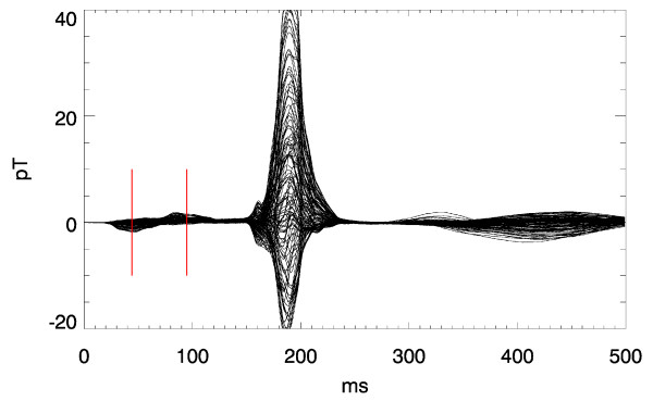
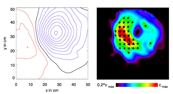
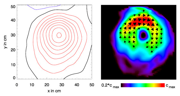
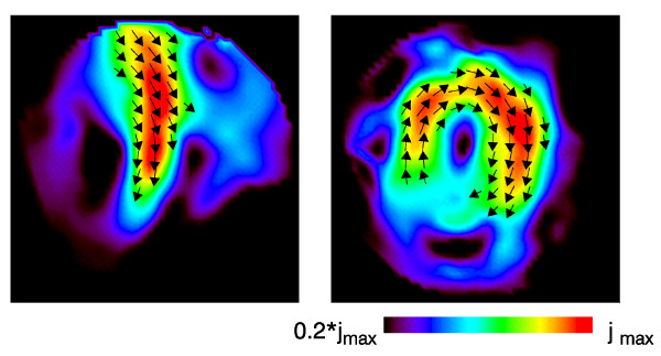
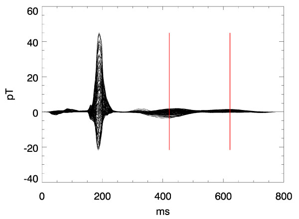
Figs. 1, 2, 3 illustrate this point: it shows two instants of the atrial excitation marked by the cursors in the MCG-butterfly-plot in Fig. 1 (a butterfly-plot is obtained by superpositioning the MCG-Signals of all channels in one display). The respective pseudo current density (PCD-) plots show very clearly and intuitively the preceding activation over the right atrium (Fig. 2, right) followed by that over the left atrium (Fig. 3, right), whereas the MFMs in Fig. 2 (left) and in Fig. 3 (left) require expert knowledge to interpret them in the same way.
Figure 1.
Butterfly plot of a multichannel magnetocardiogramm. The two cursors mark the time instants related to the visualizations shown in Fig. 2 and 3 respectively.
Figure 2.
Visualization of the atrial activation for the first time instant marked by a cursor in Fig.1. Left: Bz-map drawn as isocontour maps with a magnetic flux density difference of 0.5pT between adjacent contour lines (red: positive, i.e. directed towards the subject; blue: negative; black: Bz = 0). Right: the corresponding pseudo current density map.
Figure 3.
Visualization of the atrial activation for the second time instant marked by the respective cursor in Fig.1.
Other features of modern pseudo current density maps helped to spur interest:
i) while Hosaka and Cohen coded the information of the pseudo current density amplitude into the size of the arrows the recent display techniques added an underlying false-colour scaling to the maps.
ii) visually attractive results are achieved, if a sequence of maps is presented as an animated clip. Then the spatio-temporal dynamics of the electrophysiological function are more easily perceptible.
The question that remains open is: what do pseudo current density maps really show? Already the term "pseudo" indicates that the real current density distribution is different and may deviate considerably. This is already evident when considering the fact that the PCD-maps are only 2D-projections of a 3D reality. The initial papers of Hosaka and Cohen just gave an empirical explanation, why their maps produce an approximate image of the underlying current density distribution. Later explanations e.g. by other authors [7] relating the curl of the measured magnetic induction curl with the current density were incorrect and misleading. Therefore in the following chapters an analytically based calculation is presented that illustrates the physical justification and the limitations of this visualization method.
This paper will not deal with minimum norm estimates or other inverse methods calculating the current density from field maps. Rather, the Hosaka-Cohen transformation provides just another representation of the measured magnetic field by a postprocessing of the magnetic field data. The underlying current distribution does not enter in the calculation of the HC-transformation. We intend to clarify in which way certain features of the PCD-maps can nevertheless be related to the underlying current distribution. Some common fallacies in the interpretation of PCD maps are elucidated.
Finally we would like to stress the utility of PCD maps to provide a visualization of measurement results obtained by biomagnetic systems with very different sensor configurations. Whether magnetometers, planar gradiometers or vector magnetometers are used always similar PCD maps may be computed and will thus allow a simple cross-platform, i.e. multicentre comparability of biomagnetic investigations.
Methods
Construction of pseudo current density maps
PCD-maps are obtained from magnetic field values at a number of points in space [29,30]. Multichannel measurement systems, containing a number of SQUIDs (superconducting quantum interference devices) as magnetic field sensors, are used to measure the magnetic fields generated by electrophysiological functions in the heart (MCG = magnetocardiography), the brain (MEG = magnetoencephalography) or in other muscles or nerves (MNG = magnetoneurography). In MEG, helmet systems are used, where the SQUIDs are arranged on the surface of a sphere. For other applications, the SQUIDs are distributed more or less in a plane.
For the following discussion a simple current dipole source with current dipole moment
may be considered, i.e. a source-drain configuration with vanishing source-drain distance with unit vector and a source strength of I. This current element generates a magnetic flux density () which – according to the law of Biot-Savart – is expressed as
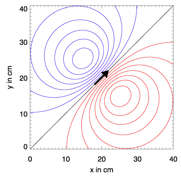
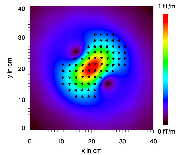
Often, planar SQUID-systems measure only one component of the -field, e.g.Bz. Fig. 4 shows the Bz-distribution calculated with (2) for a measurement plane of size 40 cm × 40 cm which is positioned 10 cm above a current dipole with a dipole moment of 1 μAm. The direction of the dipole within the x-y-plane is diagonal to the coordinate system and the magnetic flux density distribution is presented as an isocontour plot. The difference between two adjacent contour lines corresponds to a magnetic flux density difference of 0.5 pT. Red lines correspond to positive Bz-values and blue lines to negative Bz-values and the black line marks Bz = 0. The pseudo current density (x, y) in the map in Fig. 5 is gained from the Bz-values by the following transformation
Figure 4.
Bz-map of the magnetic flux density calculated from Biot-Savart's law for a current dipole (|| = 1 μAm) at a position 10 cm below the map's plane with a x-y-projection as indicated by the arrow.
Figure 5.
Psydo current density map corresponding to Fig. 4.
Thus the slopes of the Bz-surface function determine the amplitude and the direction of the pseudo current arrows (x, y). x and y are the unit vectors in x- and y-direction.
In practice the partial differential ratios and are approximated by the difference ratios and . They in turn may be easily obtained by utilizing the smooth surface function that has been used to construct the map in Fig. 4.
The arrows drawn in Fig. 5 represent the -vectors at the respective coordinates. However, only the strongest -vectors are drawn to obtain a clearer picture. Although the amplitude of is coded as the arrow length, a map with just those arrows is not as intuitive as the image shown. By underlying a false-color map scaled by the amplitude || a considerable visual enhancement of the information is achieved.
As to be anticipated the maximum amplitude occurs just above the source and also the directions of the central strongest arrow and that of the current dipole coincide. On the other hand the PCD-map does not reproduce the point-like character of the current dipole! It is rather a characteristic point-spread function of the source.
Another interesting point to mention: the Hosaka-Cohen transformation utilizes two terms of
As – according to Maxwell – curl = μ0 some authors concluded that this is the rationale for the pseudo-current density maps. However, at the sites where is measured the current density is zero and thus also curl = 0 holds. Hence no direct relation between and and curl exists at the location of the sensors. But since curl = 0 everywhere in the measurement space, the two terms that represents must exactly compensate the remaining terms of curl (from equation 4). This in turn leads to the conclusion that also the remaining terms lead to equivalent arrow maps, as it is discussed later in this paper.
Results
Pseudo current density maps of analytically solvable models
A single current dipole alone (i.e. without considering return currents) and the application of Biot-Savart's law describe a too artificial, non-physical situation. The physical background of the PCD-maps may be evaluated by:
i) modeling the MCG by a current dipole in a conductive half space, and
ii) modeling the MNG by an extended linear or curved source [28,31] or by a train of current dipoles in a conducting half space and
iii) modeling the MEG by a current dipole in a conductive sphere.
Of course also those are quite crude models of the reality but they represent basic models of sound physics and can be treated completely analytical. Thus the relations between source and PCD-map and the role of curl are exactly traceable.
Current dipole in a conductive half space
To a first approximation the MCG may be modeled by a current dipole = (px, py, pz) at 0 = (x0, y0, z0), representing the heart's electrical activity, in a conductive half space, representing the torso. The coordinate system is chosen such that z = 0 at the boundary between the "torso" with constant conductivity and the non-conducting space containing the measurement sites.
The magnetic flux density at coordinate = (x, y, z) above the half space (z > 0) is according to [32] given by
with = - 0, R = ||, K = R (R + z), and , where ∇ is the nabla operator. In Cartesian coordinates can be explicitly written as
with X = (x - x0), Y = (y - y0) and Z = (z - z0).
An inspection of (6)–(8) shows that
• pz does not contribute to () above z > 0,
• Bx(), By(), and Bz() do not depend on the position of the torso boundary as long as it is between measurement point and current dipole,
• the difference to the – field calculated by Biot-Savart's law for an isolated current dipole occurs only in (6) and (7),
• () is independent of the value of the constant conductivity in the half space.
Note that the above field properties are also valid for a horizontally layered conductor, i.e. for a conductivity σ = σ (z).
Now the Hosaka-Cohen transformation (3) is applied to (8) and yields
Particularly for X = 0, Y = 0, i.e. directly above the current dipole, one obtains
In this case is directly proportional to the x-y-projection of the current dipole moment .
This supports the argument that the Hosaka-Cohen transformation is really related to the underlying current source. However, it is also evident from (9) that additional terms are blurring and distorting the image.
On first sight the distribution of arrows might suggest that this is an image not only of the current dipole but also of the return currents (also termed: volume currents). And indeed, the model "dipole current in a conductive half space" considers the role of the return currents. However, in this special geometry, the volume currents do not contribute to Bz()as can be seen above. It becomes also evident, that the spatial distribution of away from X = 0, Y = 0 does not represent the return currents if Z is varied. Without loss in validity of equations (6)–(8) one may consider that is very close to the half space interface z = 0 and the measurement of Bz(x, y) is performed at different distances approaching . In this theoretical case, the image approximates in the limit (z - z0) = 0 a point-like distribution with vanishing (x, y) apart from the origin X = 0, Y = 0. However, the volume currents keep their amplitude independently from z as only the measurement device is moved and not the current dipole source. Thus the nature of the – image is a point spread function of non-radial symmetry.
A closer look to just one component (e.g. the x-component) of reveals that it is composed of two terms
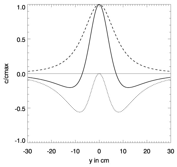
The spatial distribution of both terms is shown in Fig. 6 as a solid line. While the first term – shown as a dotted line – is radially symmetric the second term is not. Along the symmetry axis parallel to the direction of the dipole this latter term is vanishing, see the dotted line in Fig. 6. Unfortunately the second term is of the same order of magnitude as the first term. Thus cx is not directly proportional to px as the second term contains mixed terms. However, it contributes a kind of focussing effect.
Figure 6.
Spatial dependence of |p| along the symmetry axis orthogonal to the dipole direction. Dashed line: refers to the first term in eq. (11); dotted line: refers to the second term in eq. (11); solid line: both terms. Same data as in Fig. 5, however the direction of the dipole is in x-direction.
Current dipole in a conductive sphere
For a current dipole at 0 in a conductive sphere similar relations can be obtained in terms of spherical coordinates r, ϑ, φ. The magnetic flux density outside the sphere is given by [32]
with F = R(r R + ), = - 0, R = ||, r = ||, and
∇F = [r-1 R2 + R-1 () + 2R +2r] - [R + 2r + R-1 ()]0.
This expression is valid for a conductivity profile σ = σ (r).
For the case of the dipole being positioned on the z-axis at 0 = (0, 0, z0) the radial component of () becomes
with R = (r2 - 2 z0 r cosϑ + )1/2.
Then for the pseudo current density the following relation
gained from curl in spherical coordinates may be applied to (13) leading to
Particularly for ϑ = 0, i. e. directly above the current dipole, one obtains
Thus the discussion of the results follows the same lines as in the preceding chapter.
Pseudo current density maps for MNG and MEG recordings
In Fig. 7 isocontour and PCD-maps of an MNG recording using 49 channels of a planar SQUID system are shown. The centre of the system was placed over the lumbar spine with a distance of approximately 8 cm between the magnetic sensors and leg nerves coming from the left leg entering the spine. The nerve response to electrical stimulation at the ankle with amplitude of about 10 mA and duration of 100 μs was recorded. 9.000 responses were averaged to improve the pure signal-to-noise ratio. In Fig. 7, top, an isocontour map of the Bz-field component 15 ms after the stimulus and in Fig. 7, bottom, the corresponding PCD-map are shown. Inspecting the isocontour map from Fig. 7 only a raw understanding of an underlying current and its direction corresponding to the zero line of the map is possible for an expert. The PCD-map allows a more intuitive conclusion that the underlying nerve current is extremely extended and slightly curved.
Figure 7.
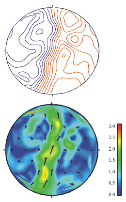
Top: Bz-map of an electrically stimulated nerve signal recorded over the lumbar spine (contour step 1fT), and bottom: its HC-transformation (scale in fT/cm).
Fig. 8 displays maps of an acoustically evoked MEG recorded in a helmet system with 93 channels. The spherical maps are unfolded, the nose is situated at the top, and ears are at the right and left side, respectively. The measurement recorded the brain response to acoustic stimulation with a 1 kHz sinusoidal tone. 30 stimuli were averaged. In Fig. 8, top, an isocontour map of the radial field component at the occurrence of the maximum of the response (about 100 ms after stimulus; termed "N100") is shown and in Fig. 8, bottom, the corresponding PCD-map. Using the isocontour map from Fig. 8 the number of sources and their configuration cannot be concluded. On the other hand from inspecting the PCD-map one can conclude that two separate focal sources are active, one in each hemisphere in the corresponding acoustic cortex.
Figure 8.
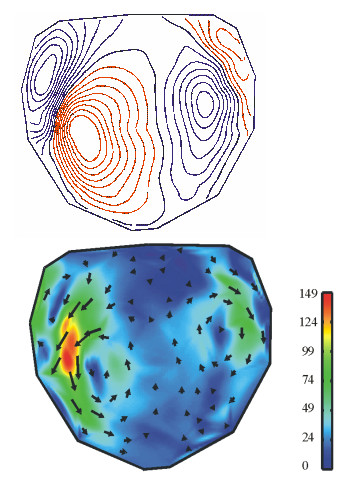
Top: Br-map of an acoustically stimulated (1 kHz) N100 signal (contour step 50fT), and bottom: its HC-transformation (scale in fT/cm).
Discussion
Alternative pseudo current density maps and corresponding hardware realizations
The Hosaka-Cohen transformation is nothing else but a combination of partial derivatives of components of (). Planar gradiometers are hardware realizations that provide an approximation of the partial derivative of (). Thus, the SQUID-chip introduced by [33], which is a combination of x- and y-gradiometers, provides -if wired accordingly- just the approximation of (x, y) (cf. Fig. 9). Consequently, the software of the first SQUID-systems of that design contained a program called "arrow mapper".
Figure 9.
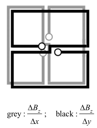
Planar Bz-gradiometer as a hardware realization for performing direct HC-transformations and the related difference quotients.
As mentioned before an interrelation between and curl exists. Equation (4) may be rewritten as
For this case curl can be written as a sum of three vectors , , and where is identical to (3), i.e.
curl = + + (18)
with  .
.
Outside the body + + = 0 due to curl = 0. Therefore + just cancel and – ( + ) will provide the same pseudo current density map as well!
In addition, if curl = 0 then
and only 2 components Bx, By, or Bx, Bz, or By, Bz are necessary to construct , , and .
For example, by exploiting relations (19) the three vectors constructed with Bx, By yield
The last relation for may be easily realized by another SQUID-system hardware consisting of vertically oriented planar gradiometers [34]. This system approximates the partial derivative of By and Bx with respect to z. Thus also with that system a direct acquisition of the pseudo current density map is possible (cf. Fig. 10).
Figure 10.
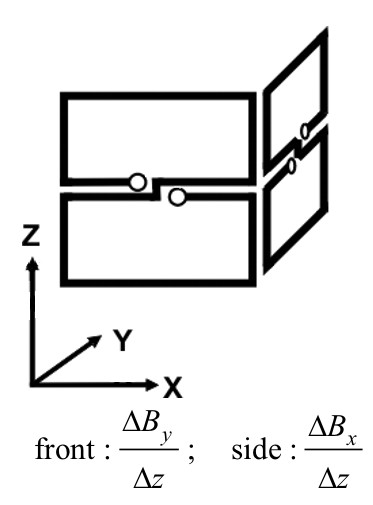
Planar vertical gradiometers as a hardware realization for performing direct HC-transformations and the related difference quotients.
Finally, the newer vectormagnetometer systems [35,36] also allow an appropriate combination of partial derivatives leading to
Again, the same pseudo current density map occurs, but the signal to noise ratio will be enhanced, as all three vector components of () are utilized.
Visualizing dynamics by creating a sequence of pseudo current density maps for MCG data
The perception of dynamic phenomena is considerably enhanced by viewing movies.
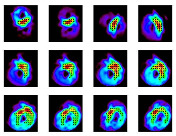
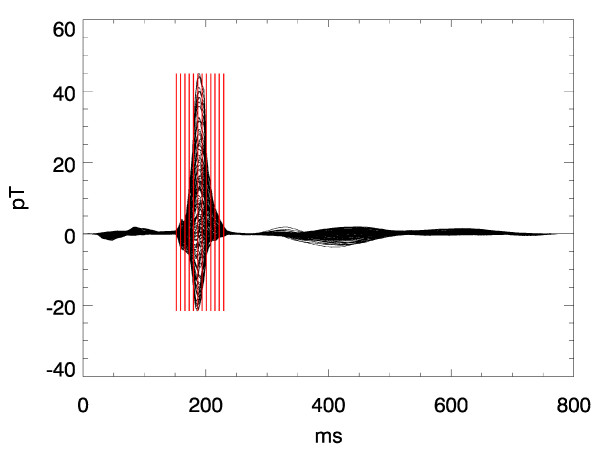
A sequence of frames might give an impression of what can be expressed by a movie clip. Figs. 12 displays such a sequence of frames showing the evolution of PCD-maps gained from the multichannel MCG during a heart beat of a healthy volunteer. Due to the higher dynamics during the QRS-complex the frame rate is higher there than during the ST-phase. The start of the activation sequence in the septum, the downwards propagation to the apex, and the following depolarization (Figs. 11 and 12) are visible as it is expected from textbook knowledge. The corresponding movie is attached as an additional data file (see Additional file 1).
Figure 12.
Frames of a video-sequence of pseudo current density maps during the QRS-complex.
Figure 11.
Butterfly plot of a multichannel magnetocardiogram. The cursors indicate the time instants of the frames in Fig. 12.
It is obvious that a PCD-map at the end of the T-wave may serve more consistently for evaluating dispersion of repolarization (Fig. 14) than a Bz-map with its zero-isofield-line.
Figure 14.
Frames of a video-sequence of pseudo current density maps during the T- and U-wave.
Another interesting aspect is the difference in spatial field configuration between end of the T-wave and the U-wave. The real nature of the U-wave is still under debate. But any hypothesis should consider the fact shown here (and confirmed in many other cases) that the spatial origin of the excitation that generates the ECG or MCG at the end of the T-wave differs markedly from that of the U-wave (Figs. 13 and 14).
Figure 13.
Butterfly plot of a multichannel magnetocardiogram. The cursors indicate the time instants of the frames in Fig. 14.
Conclusion
In this work we presented examples of electrophysiological measurements where the use of PCD-maps is meaningful. PCD-maps allow in these selected cases an estimate of the underlying currents and also of the temporal behavior of the current propagation. On the other hand, the PCD-maps are only a 2D-presentation of a 3D-current distribution and may deviate considerable from the real current distribution.
We described the analytical basis of PCD-maps and showed that there exist alternative PCD-map presentations if other field components then Bz are also taken into account. Additionally we extended the PCD-map method to spherical coordinates as used in MEG.
PCD-maps are very interesting nowadays due to hardware realizations by special designed coil configurations or vector magnetometers. Vector magnetometry allows the recording of all magnetic field components and thus the direct realization of all proposed PCD-map cases.
The advantages of pseudo current density maps besides their intuitive character ("maximum signal is where the action is") are their model- and hardware-independence. While sophisticated inverse methods and filter techniques (e.g. the synthetic aperture beamformer [37]) may lead to more exact results with respect to the real current density distribution, they are hard to validate and require advanced data processing. In multicentric clinical studies, where comparability of measurement results between different groups is a key issue, PCD-maps might serve as a basis to exchange results. PCD-maps from such different SQUID-systems as those with planar horizontal, planar vertical magnetometers or gradiometers, or vectormagnetometers differ only slightly and are still traceable back to the original measurement results (up to an additive constant).
Competing interests
The author(s) declare that they have no competing interests.
Authors' contributions
WH: theory, mathematics
US: critical revision and supportive contributions
MB: critical revision, chapter on MNG and MEG recordings
OK: critical revision, results of MCG-investigations
AM: clinical investigation and support
HK: corresponding author, drafting of the manuscript, visualization, animation, and final approval
Supplementary Material
MCG-movies. The attached Power Point file "MCG-movies.ppt" contains movies (animated GIF; runs only in recent Power Point versions) of the map sequences partly shown in figures 2, 3, and 13.
Acknowledgments
Acknowledgements
The biomagnetic measurements for the example MCG-signal were obtained in a study described in reference 38. The medical writer of this paper (A.M.) was the responsible medical investigator of that study which had been funded by the German Federal Ministry for Education, Research and Technology under Grant No. 01 KX 9912/8.
Contributor Information
Wolfgang Haberkorn, Email: wolfgang.haberkorn@ptb.de.
Uwe Steinhoff, Email: uwe.steinhoff@ptb.de.
Martin Burghoff, Email: martin.burghoff@ptb.de.
Olaf Kosch, Email: olaf.kosch@socratec-pharma.de.
Andreas Morguet, Email: morguet@medizin.fu-berlin.de.
Hans Koch, Email: hans.koch@ptb.de.
References
- Cohen D, Lepeschkin E, Hosaka H, Massell B, Myers G. Part I — Abnormal Patterns and Physiological Variations in Magnetocardiograms. J Electrocardiol. 1976;9:398–409. doi: 10.1016/S0022-0736(76)80040-4. [DOI] [PubMed] [Google Scholar]
- Cohen D, Hosaka H. Part II — Magnetic Field Produced by a Current Dipole. J Electrocardiol. 1976;9:409–417. doi: 10.1016/S0022-0736(76)80041-6. [DOI] [PubMed] [Google Scholar]
- Hosaka H, Cohen D, Cuffin BN, Horacek BM. Part III — The Effect of the Torso Boundaries on the Magnetocardiogram. J Electrocardiol. 1976;9:418–425. doi: 10.1016/S0022-0736(76)80042-8. [DOI] [PubMed] [Google Scholar]
- Hosaka H, Cohen D. Part IV — Visual Determination of Generators of the Magnetocardiogram. J Electrocardiol. 1976;9:426–432. doi: 10.1016/S0022-0736(76)80043-X. [DOI] [PubMed] [Google Scholar]
- Wikswo JP. The Magnetic Inverse Problem for NDE. In: Weinstock H, editor. SQUID Sensors: Fundamentals, Fabrication and Applications. Dordrecht: Kluwer Academic Publishers; 1996. pp. 629–695. [Google Scholar]
- Tan S. PhD dissertation. Department of Physics and Astronomy, Vanderbilt University; 1992. Linear System Imaging and its Applications to Magnetic Measurements by SQUID Magnetometers. [Google Scholar]
- Miyashita T, Kandori A, Tsukada K, Sato M, Terada Y, Horigome H, Mitsui T. Construction of Tangential Vectors from Normal Cardiac Magnetic Field Components. Proc 20th Ann Int Conf IEEE/EMBS Oct 29-Nov1, Hong Kong. 1998. pp. 520–523.
- Hailer B, Chaikovsky I, Auth-Eisernitz S, Schäfer H, Steinberg F, Grönemeyer DHW. Magnetocardiography in Coronary Artery Disease with a New System in an Unshielded Setting. Clin Cardiol. 2003;26:465–471. doi: 10.1002/clc.4960261007. [DOI] [PMC free article] [PubMed] [Google Scholar]
- Nenonen J, Montonen J, Koskinen R. Surface Gradient Analysis of Atrial Activation from Magnetocardiographic Maps. Int J Bioelectromagnetism. 2003;5:98–99. [Google Scholar]
- http://www.cryoton.webzone.ru/softmcg.htm
- Hailer B, Van Leeuwen P, Chaikovsky I, Auth-Eisernitz S, Schäfer H, Grönemeyer D. The value of magnetocardiography in the course of coronary intervention. Ann Noninvasive Electrocardiol. 2005;10:188–96. doi: 10.1111/j.1542-474X.2005.05625.x. [DOI] [PMC free article] [PubMed] [Google Scholar]
- Hailer B, Chaikovsky I, Auth-Eisernitz S, Schafer H, Van Leeuwen P. The value of magnetocardiography in patients with and without relevant stenoses of the coronary arteries using an unshielded system. Pacing Clin Electrophysiol. 2005;28:8–16. doi: 10.1111/j.1540-8159.2005.09318.x. [DOI] [PubMed] [Google Scholar]
- Koch H. Recent advances in magnetocardiography. J Electrocardiol. 2004;37:117–22. doi: 10.1016/j.jelectrocard.2004.08.035. [DOI] [PubMed] [Google Scholar]
- Kandori A, Shimizu W, Yokokawa M, Kamakura S, Miyatake K, Murakami M, Miyashita T, Ogata K, Tsukada K. Reconstruction of action potential of repolarization in patients with congenital long-QT syndrome. Phys Med Biol. 2004;49:2103–15. doi: 10.1088/0031-9155/49/10/019. [DOI] [PubMed] [Google Scholar]
- Kandori A, Shimizu W, Yokokawa M, Noda T, Kamakura S, Miyatake K, Murakami M, Miyashita T, Ogata K, Tsukada K. Identifying patterns of spatial current dispersion that characterise and separate the Brugada syndrome and complete right-bundle branch block. Med Biol Eng Comput. 2004;42:236–44. doi: 10.1007/BF02344637. [DOI] [PubMed] [Google Scholar]
- Kandori A, Shimizu W, Yokokawa M, Maruo T, Kanzaki H, Nakatani S, Kamakura S, Miyatake K, Murakami M, Miyashita T, Ogata K, Tsukada K. Detection of spatial repolarization abnormalities in patients with LQT1 and LQT2 forms of congenital long-QT syndrome. Physiol Meas. 2002;23:603–14. doi: 10.1088/0967-3334/23/4/301. [DOI] [PubMed] [Google Scholar]
- Sato M, Terada Y, Mitsui T, Miyashita T, Kandori A, Tsukada K. Visualization of atrial excitation by magnetocardiogram. Int J Cardiovasc Imaging. 2002;18:305–12. doi: 10.1023/A:1015597910933. [DOI] [PubMed] [Google Scholar]
- Kandori A, Kanzaki H, Miyatake K, Hashimoto S, Itoh S, Tanaka N, Miyashita T, Tsukada K. A method for detecting myocardial abnormality by using a current-ratio map calculated from an exercise-induced magnetocardiogram. Med Biol Eng Comput. 2001;39:29–34. doi: 10.1007/BF02345263. [DOI] [PubMed] [Google Scholar]
- Tsukada K, Miyashita T, Kandori A, Mitsui T, Terada Y, Sato M, Shiono J, Horigome H, Yamada S, Yamaguchi I. An iso-integral mapping technique using magnetocardiogram, and its possible use for diagnosis of ischemic heart disease. Int J Card Imaging. 2000;16:55–66. doi: 10.1023/A:1006376326755. [DOI] [PubMed] [Google Scholar]
- Kandori A, Kanzaki H, Miyatake K, Hashimoto S, Itoh S, Tanaka N, Miyashita T, Tsukada K. A method for detecting myocardial abnormality by using a total current-vector calculated from ST-segment deviation of a magnetocardiogram signal. Med Biol Eng Comput. 2001;39:21–8. doi: 10.1007/BF02345262. [DOI] [PubMed] [Google Scholar]
- Weber Dos Santos R, Kosch O, Steinhoff U, Bauer S, Trahms L, Koch H. MCG to ECG source differences: measurements and a two-dimensional computer model study. J Electrocardiol. 2004;37:123–7. doi: 10.1016/j.jelectrocard.2004.08.036. [DOI] [PubMed] [Google Scholar]
- Kandori A, Miyashita T, Tsukada K, Hosono T, Miyashita S, Chiba Y, Horigome H, Shigemitsu S, Asaka M. Prenatal diagnosis of QT prolongation by fetal magnetocardiogram – use of QRS and T-wave current-arrow maps. Physiol Meas. 2001;22:377–87. doi: 10.1088/0967-3334/22/2/309. [DOI] [PubMed] [Google Scholar]
- Kandori A, Hosono T, Kanagawa T, Miyashita S, Chiba Y, Murakami M, Miyashita T, Tsukada K. Detection of atrial-flutter and atrial-fibrillation waveforms by fetal magnetocardiogram. Med Biol Eng Comput. 2002;40:213–7. doi: 10.1007/BF02348127. [DOI] [PubMed] [Google Scholar]
- Hosono T, Shinto M, Chiba Y, Kandori A, Tsukada K. Prenatal diagnosis of fetal complete atrioventricular block with QT prolongation and alternating ventricular pacemakers using multi-channel magnetocardiography and current-arrow maps. Fetal Diagn Ther. 2002;17:173–6. doi: 10.1159/000048033. [DOI] [PubMed] [Google Scholar]
- Kandori A, Oe H, Miyashita K, Ohira S, Naritomi H, Chiba Y, Ogata K, Murakami M, Miyashita T, Tsukada K. Magneto-encephalographic measurement of neural activity during period of vertigo induced by cold caloric stimulation. Neurosci Res. 2003;46:281–8. doi: 10.1016/S0168-0102(03)00092-0. [DOI] [PubMed] [Google Scholar]
- Oe H, Kandori A, Murakami M, Miyashita K, Tsukada K, Naritomi H. Cortical functional abnormality assessed by auditory-evoked magnetic fields and therapeutic approach in patients with chronic dizziness. Brain Res. 2002;957:373–81. doi: 10.1016/S0006-8993(02)03555-2. [DOI] [PubMed] [Google Scholar]
- Kandori A, Oe H, Miyashita K, Date H, Yamada N, Naritomi H, Chiba Y, Murakami M, Miyashita T, Tsukada K. Visualisation method of spatial interictal discharges in temporal epilepsy patients using magneto-encephalogram. Med Biol Eng Comput. 2002;40:327–31. doi: 10.1007/BF02344215. [DOI] [PubMed] [Google Scholar]
- Burghoff M, Mackert BM, Haberkorn W. Visualization of action currents in peripheral nerves from the biomagnetic field. Biomed Tech. 2005;50:179–80. [Google Scholar]
- Koch H. SQUID Magnetocardiography: Status and Perspectives. IEEE Trans Appl Superconductivity. 2001;11:49–59. doi: 10.1109/77.919284. [DOI] [Google Scholar]
- Hämäläinen M, Hari R, Ilmoniemi RJ, Knuutila J, Lounasmaa O. Magnetoencephalography – Theory, Instrumentation, and Applications to Noninvasive Studies of the Working Human Brain. Rev Mod Phys. 1993;65:413–497. doi: 10.1103/RevModPhys.65.413. [DOI] [Google Scholar]
- Kosch O, Burghoff M, Jazbinsek V, Steinhoff U, Trontelj Z, Trahms L. Extended source models in integrated body surface potential and magnetic field mapping. Biomed Eng. 2001;46:144–146. [Google Scholar]
- Sarvas J. Basic Mathematical and Electromagnetic Concepts of the Biomagnetic Inverse Problem. Phys Med Biol. 1987;32:11–22. doi: 10.1088/0031-9155/32/1/004. [DOI] [PubMed] [Google Scholar]
- Hämäläinen MS. A 24-Channel Planar Gradiometer: System Design and Analysis of Neuromagnetic Data. In: Williamson SJ, Hoke M, Stroink G, Kotani M, editor. Advances in Biomagnetism. New York: Plenum Press; 1989. pp. 639–644. [Google Scholar]
- Kandori A, Tsukada K, Haruta Y, Noda Y, Terada Y, Mitsui T, Sekihara K. Reconstruction of two-dimensional Current Distribution from Tangential MCG measurement. Phys Med Biol. 1996;41:1705–1716. doi: 10.1088/0031-9155/41/9/010. [DOI] [PubMed] [Google Scholar]
- Burghoff M, Schleyerbach H, Drung D, Trahms L, Koch H. A Vector Magnetometer Module for Biomagnetic Application. IEEE Trans Appl Superconductivity. 1999;9:4069–4072. doi: 10.1109/77.783920. [DOI] [Google Scholar]
- Stolz R, Zakosarenko V, Schulz M, Chwala A, Fritzsch L, Meyer HG, Koestlin EO. Magnetic full-tensor SQUID gradiometer system for geophysical applications. The Leading Edge. 2006;25:178–180. doi: 10.1190/1.2172308. [DOI] [Google Scholar]
- Robinson SE, Vrba J. Functional Neuroimaging by Synthetic Aperture Magnetometry (SAM) In: Yoshimoto T, Kotani M, Kuriki S, Karibe H, Nakasato N, editor. Recent Advances in Biomagnetism, Proc 11th Int Conf Biomagnetism. Sendai: Tohoku University Press; 1999. pp. 302–305. [Google Scholar]
- Morguet A, Behrens S, Kosch O, Lange C, Zabel M, Selbig D, Munz DL, Schultheiss HP, Koch H. Myocardial Viability Evaluation using Magnetocardiography in Patients with Coronary Artery Disease. Coronary Artery Disease. 2004;15:155–162. doi: 10.1097/00019501-200405000-00004. [DOI] [PubMed] [Google Scholar]
Associated Data
This section collects any data citations, data availability statements, or supplementary materials included in this article.
Supplementary Materials
MCG-movies. The attached Power Point file "MCG-movies.ppt" contains movies (animated GIF; runs only in recent Power Point versions) of the map sequences partly shown in figures 2, 3, and 13.


