Abstract
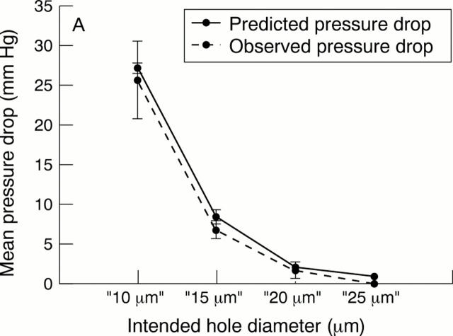
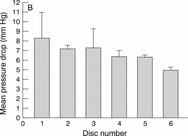
AIMS—(I) To examine whether small holes produced by 248 nm excimer laser ablation in a polymer substrate could consistently produce a pressure drop in the desired target range (5-15 mm Hg) at physiological aqueous flow rates for use as an internal flow restrictor in a glaucoma drainage device, and (ii) to investigate whether external leakage could be reduced in comparison with conventional tube and plate glaucoma drainage devices by redesigning the exterior cross sectional shape of the portion contained within the sclerocorneal tunnel. METHODS—Single holes with target diameters of 10 µm, 15 µm, 20 µm, and 25 µm were drilled using a 248 nm excimer laser in sample discs (n=6 at each diameter) punched from a 75 µm thick polyimide sheet. Sample discs were tested in a flow rig designed to measure the pressure drop across the discs. Using filtered, degassed water at a flow rate of 1.4 µl/min repeated flow measurements were taken (n=6) for each disc. After flow testing, all discs were imaged using a scanning electron microscope and the dimensions of each hole were derived using image analysis software. In the external leakage study, corneoscleral buttons (n=13) were prepared from cadaver pig eyes and mounted on an artificial anterior chamber infused with Tyrode solution. After the pressure had stabilised, standard occluded silicone tube implants were inserted through 23 gauge needle stab incisions at the limbus. These were compared against prototype PMMA implants with a novel shape profile inserted through 1.15 mm width microvitreoretinal (MVR) stab incisions at the limbus. The infusion rate was maintained and a second pressure measurement was taken when the pressure had stabilised. The difference between the first and second pressure measurement was then compared, as an index of external leakage. RESULTS—Ablated tubes were found to have a near perfect circular outline on both the entry and exit side. The observed pressure drops across the ablated sample discs at each target diameter were as follows: 10 µm, mean 25.66 (SD 4.9) mm Hg; 15 µm, 6.7 (1.15); 20 µm, 1.66 (1.07); and 25 µm, <0.1 mm Hg. A strong correlation was observed between observed pressure drops and those predicted by Poiseuille's formula (R2 =0.996). Target ablations of 15 µm diameter produced tubes that consistently achieved a pressure drop within the desired range (5-15 mm Hg). In the external leakage study, preinsertion pressures (mm Hg; mean (SD)) were 19.00 (4.3) (conventional method) and 20.00 (3.9) (new technique with PMMA prototypes). Post-insertion pressures were significantly reduced (10.40 (7.7); p<0.01) for the conventional technique and were essentially unchanged for the new technique (18.80 (4.9); p>0.1). CONCLUSIONS—It was shown that it is possible, in principle, to control the dimensions of a manufactured tubular lumen in a glaucoma drainage device accurately enough to provide consistent protection from hypotony in the early period after glaucoma filtration surgery. By redesigning the external profile of glaucoma drainage device and incision technique, it was also shown that it is possible to eliminate uncontrolled external leakage.
Full Text
The Full Text of this article is available as a PDF (212.3 KB).
Figure 1 .
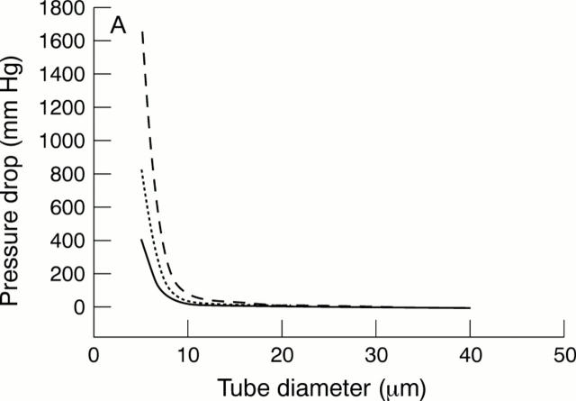
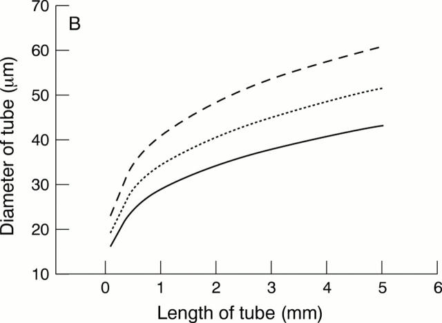
(A) The pressure drop across a tube versus tube diameter from Poiseuille's formula6 at a flow rate of 0.7 µl/min (solid line), 1.4 µl/min (dotted line), and 2.8 µl/min (broken line): pressure drop = 128nlQ/136πd4, where n = aqueous viscosity = 0.001 Ns/m2; l = length = 0.075 mm in this study; Q = aqueous flow rate, d = diameter (metres). For multiple tubes in parallel,6 the pressure drop will be given by: pressure drop = 128nlQ/136πd4 N, where N = number of tubes in parallel. (B)The relation between tube diameter and length, calculated from the Poiseuille's formula, for a pressure drop across the tube of 5 mm Hg at a flow rate of 0.7 µl/min (solid line), 1.4 µl/min (dotted line), and 2.8 µl/min (broken line).
Figure 2 .
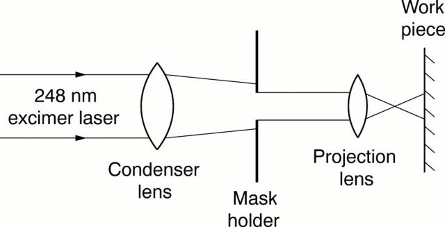
A schematic drawing of the 248 nm (krypton/fluorine) excimer laser delivery system used (Model EX-PS-2000, Exitech Ltd, Oxford, UK) (not to scale). Beam area at the target surface, and hence ablation diameter, was controlled by the mask aperture. The pulse repetition rate was set at 40 Hz and a total of 100 pulses were delivered to each disc. Specimens with target diameters of 10 and 15 µm were ablated at a fluence of 200 mJ/cm2 with mask diameters of 300 and 450 µm respectively. Those with target diameters of 20 and 25 µm were ablated at 170 mJ/cm2 with mask diameters of 600 and 750 µm.
Figure 3 .
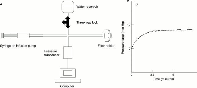
(A) The flow rig used was similar to that previously described for flow evaluation in GDDs.5 8 (B) A typical flow tracing, demonstrating stabilisation of the pressure recording within approximately 3 minutes of commencing infusion.
Figure 4 .
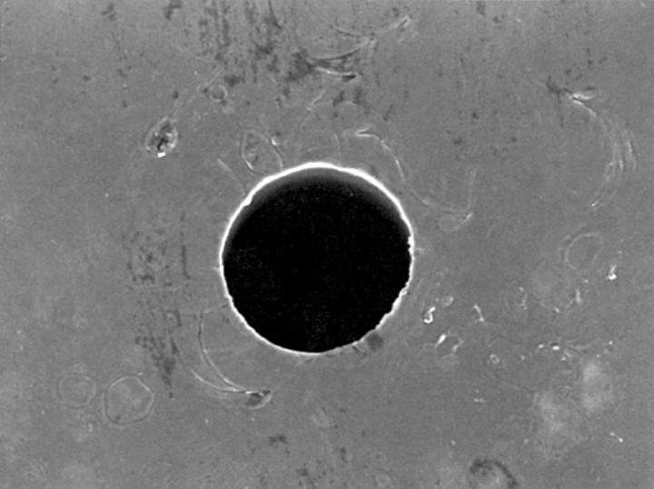
The inner edge of the ablated holes viewed at 90° to the specimen surface by scanning electron microscopy were outlined on each side using image analysis software. The diameter a perfect circle of equivalent area was then calculated to estimate entry and exit diameters.
Figure 5 .
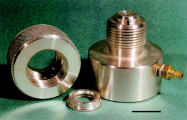
An artificial anterior chamber designed to mount cadaveric porcine corneoscleral buttons.
Figure 6 .
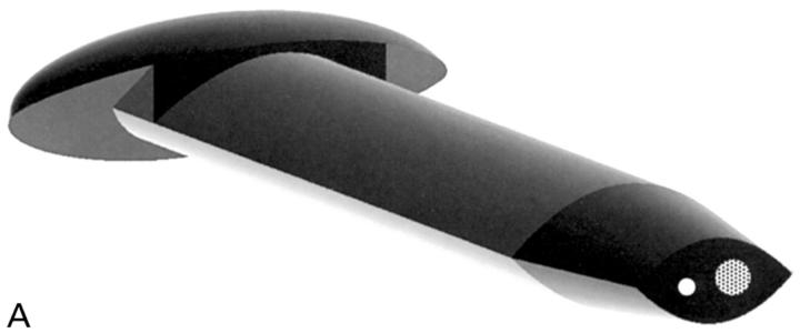
(A) This is one embodiment of a novel glaucoma drainage device (patent applied for) incorporating a small diameter hole (white circle) to provide the required fistular resistance and a larger diameter hole (dotted circle) temporarily occluded by a thin ablatable membrane. To give the lowest final IOP, resistance is bypassed by ablating this thin membrane using a YAG laser delivered through a gonioscope once a mature bleb is established. The external cross sectional shape of this implant is designed to bear evenly on the internal aspect of a standard microvitreoretinal (MVR) slit incision, so as to eliminate external leakage after placement. (B) A schematic drawing of the glaucoma drainage device in situ. A limbal slit incision was made parallel to the iris plane using a standard 1.19 mm width MVR blade to enter the anterior chamber. The occluded glaucoma drainage device was inserted through the wound, and sutured with 10/0 nylon.
Figure 7 .
 |
Selected References
These references are in PubMed. This may not be the complete list of references from this article.
- Brubaker R. F. Flow of aqueous humor in humans [The Friedenwald Lecture]. Invest Ophthalmol Vis Sci. 1991 Dec;32(13):3145–3166. [PubMed] [Google Scholar]
- Coleman A. L., Hill R., Wilson M. R., Choplin N., Kotas-Neumann R., Tam M., Bacharach J., Panek W. C. Initial clinical experience with the Ahmed Glaucoma Valve implant. Am J Ophthalmol. 1995 Jul;120(1):23–31. doi: 10.1016/s0002-9394(14)73755-9. [DOI] [PubMed] [Google Scholar]
- Krawczyk C. H. Glaucoma drainage devices and the FDA. Ophthalmology. 1995 Nov;102(11):1581–1582. doi: 10.1016/s0161-6420(95)30825-1. [DOI] [PubMed] [Google Scholar]
- Lee V. W. Glaucoma "valves"--truth versus myth. Ophthalmology. 1998 Apr;105(4):567–568. doi: 10.1016/S0161-6420(98)94000-3. [DOI] [PubMed] [Google Scholar]
- Lim K. S. Cell and protein adhesion studies in glaucoma drainage device development. The AGFID project team. Br J Ophthalmol. 1999 Oct;83(10):1168–1171. doi: 10.1136/bjo.83.10.1168. [DOI] [PMC free article] [PubMed] [Google Scholar]
- McEWEN W. K. Application of Poiseuille's law to aqueous outflow. AMA Arch Ophthalmol. 1958 Aug;60(2):290–294. doi: 10.1001/archopht.1958.00940080306017. [DOI] [PubMed] [Google Scholar]
- Porter J. M., Krawczyk C. H., Carey R. F. In vitro flow testing of glaucoma drainage devices. Ophthalmology. 1997 Oct;104(10):1701–1707. doi: 10.1016/s0161-6420(97)30077-3. [DOI] [PubMed] [Google Scholar]
- Prata J. A., Jr, Mérmoud A., LaBree L., Minckler D. S. In vitro and in vivo flow characteristics of glaucoma drainage implants. Ophthalmology. 1995 Jun;102(6):894–904. doi: 10.1016/s0161-6420(95)30937-2. [DOI] [PubMed] [Google Scholar]
- Reiss G. R., Lee D. A., Topper J. E., Brubaker R. F. Aqueous humor flow during sleep. Invest Ophthalmol Vis Sci. 1984 Jun;25(6):776–778. [PubMed] [Google Scholar]


