

Abstract
Third-harmonic generation (THG) microscopy provides images of unstained biological samples based on spatial variations in third-order nonlinear susceptibility, refractive index, and dispersion. In this study, we establish quantitative values for the third-order nonlinear susceptibilities of several solvents (water, ethanol, glycerol), physiological aqueous (ions, amino acids, polypeptides, bovine serum albumin, glucose) and lipid (triglycerides, cholesterol) solutions as a function of solute concentration in the 1.05–1.25 μm excitation range. We use these data in conjunction with imaging experiments to show that THG imaging with ∼1.2 μm excitation lacks specificity and sensitivity to detect physiological ion concentration changes, and that nonaqueous structures such as lipid bodies provide a more robust source of signal. Finally, we illustrate the impact of index-matching liquids in THG images. These data provide a basis for interpreting biological THG images and for developing additional applications.
INTRODUCTION
Third-harmonic generation (THG) microscopy (1) is a nonlinear imaging modality that can provide images of biological samples based on spatial variations in third-order nonlinear susceptibility (χ(3)), refractive index (n), and dispersion (n3ω–nω) (2,3). Since THG is the coherent conversion of light with frequency ω into light with frequency 3ω, it requires a single excitation beam (usually a ∼80 MHz femtosecond pulse train in the 1.1–1.5 μm wavelength range), and is easily combined with other femtosecond techniques such as two-photon-excited fluorescence microscopy (2PEF) and second-harmonic generation microscopy (4,5), or femtosecond pulse-induced ablation (6,7).
Two attractive characteristics of THG microscopy are that it can be used to image unstained cells and tissues, and that it provides information complementary to fluorescence. Several demonstrations have been reported in recent years, using THG to image tissue architecture (3), cultured neurons (8), red blood cells (9,10), plant tissue (2,4,5), embryonic development (11,12), skin biopsy samples (13), oral mucosa (14), and lipid bodies (5), as well as ion flux- (15) and mitochondria-related signals (16).
Third-harmonic generation microscopy possesses specific imaging properties and contrast mechanisms related to coherence and wavelength tripling, which have been investigated (1,3,17–19). In particular, it has been established that no far-field TH signal is obtained when the excitation beam is strongly focused inside a normally dispersive, isotropic medium. This property has been related to the Gouy phase shift experienced by the fundamental beam near focus, which causes destructive interference between the TH waves created over the focal volume (1,20,21). Under moderate focusing conditions, dispersion further reduces the efficiency of THG from thick samples. As a consequence, THG microscopy specifically detects interfaces or heterogeneities between two media that differ in linear or nonlinear properties. Inclusions with size comparable to half the extent of the focal volume also optimize phase matching and coherently enhance the signal (18,19). When such an interface is present at the beam focus, the signal is proportional to 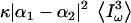 , where κ depends on sample geometry, Iω is the excitation intensity, and |α1−α2| depends on the optical properties of the two media. For example, when tightly focusing the beam on an interface, α → χ(3); and alternatively, under moderate focusing conditions where dispersion limits TH efficiency, α → χ(3)/(n3ω(n3ω–nω)). Knowledge about the nonlinear susceptibilities of biological solutions is therefore critical when interpreting THG images of cells and tissues. However, one issue that limits the development of THG microscopy as a more widespread biological imaging technique is that there are few published quantitative data on the matter.
One principal aim of this study is to establish reliable data for the nonlinear susceptibilities of biologically relevant liquids in the 1.05–1.25 μm range, most appropriate for minimally invasive THG imaging (11,22). We use the Maker fringe geometry originally proposed by Kajzar and Messier (23) for characterizing solvents based on the coherent nature of THG. We first control the accuracy of our measurements by comparing our data on water and ethanol with published values. We then characterize the nonlinear susceptibility of physiological aqueous (ions, amino acids, polypeptides, bovine serum albumin, glucose) and lipid (triglycerides, cholesterol) solutions as a function of wavelength and solute concentration. We use these data in conjunction with imaging experiments to address the open issue of THG signal variations associated with ionic concentration changes near cell membranes (15). We also show that nonaqueous structures such as lipid bodies provide a much stronger source of contrast than concentration-related changes with ∼1.2 μm excitation and can be selectively imaged in unstained hepatocytes. Finally, we illustrate the impact of index-matching liquids such as glycerol on THG images.
METHODS
Measurements of liquid nonlinear susceptibility and dispersion
Nonlinear susceptibilities were measured at 20°C as proposed in Kajzar and Messier (23) using the arrangement depicted in Fig. 1. The excitation source was an optical parametric oscillator (OPO, APE, Berlin, Germany) driven by a Titanium:Sapphire (Ti:S) oscillator (Coherent, Santa Clara, CA) and providing a 200-fs, 76-MHz pulse train with central wavelength tunable in the range 1060–1260 nm. The excitation beam was weakly focused in the sample (Rayleigh length ∼400 μm) with a 50 mm-focal length lens, and the resulting third-harmonic light was detected in the transmitted direction using a photomultiplier tube (Fig. 1 a). The liquid sample was introduced in a wedge-shaped cell of thickness ranging from 0 to 100 μm (Fig. 1 b). Two cells with 3 mm-thick walls respectively made of fused silica and of BK7 glass were used to measure the liquid optical properties. Reference values for the nonlinear susceptibilities of the glasses were taken from Bosshard et al. (24). By moving the cell perpendicularly to the optical axis, the path-length of the beam inside the liquid (L) could thus be linearly increased. The cell diameter was 25 mm, corresponding to a wedge angle of ∼4 × 10⁻³ rad. The diameter of the excitation beam was ∼10 μm, which limited the path-length change through the liquid across the focal volume to <40 nm. Therefore, the cell walls could be considered parallel within this distance range. As described later, changing the liquid cell thickness (L) produced Maker fringes in the THG signal (Fig. 2) with amplitude proportional to 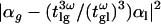 with α=χ(3)/n3ω(n3ω−nω)(see Eq. 7), where χ(3) is the third-order susceptibility, n3ω is the linear index at the harmonic frequency, (n3ω–nω) is the refractive index dispersion between the fundamental and the harmonic frequency,
  are transmission coefficients at the interfaces, and the indices g and l stand for glass and liquid, respectively. The above equation assumes that
  , which was verified within 1% in our conditions. Cell thickness range was kept small to limit fringe damping caused by the large source bandwidth and by group velocity mismatch between the fundamental and harmonic pulses (25–27). We confirmed the third-harmonic nature of the signal by verifying that it scaled with the cube of the excitation intensity when the cell was filled with water (Fig. 2 a) and with a saturated calcium-chloride aqueous solution (not shown). Measurements were normalized to a reference signal to reduce uncertainties due to OPO intensity fluctuations. For that purpose, a fraction (≈10%) of the excitation beam was focused on a glass slide to produce a reference signal used to normalize the measured amplitude of the fringes (Fig. 1 a). This method was effective even in the presence of large fluctuations (Fig. 2, c and d), and led to an uncertainty of <3% in amplitude measurements. When characterizing water-soluble compounds, experiments were performed for different concentrations ranging from pure water to the limit of solubility of the compound. Finally, nonlinear susceptibilities were estimated by combining the results obtained with the two different cells (silica and BK7). When not found in the literature, (nl,3ω−nl,ω) was deduced from the fringe period and in this case was the main source of uncertainty in the experiments.
FIGURE 1.

Experimental setup for susceptibility measurements. (A) Measurement line (see text). Ti:S, Titanium:Sapphire laser; OPO, optical parametric oscillator; HWP, half-wave plate; PBS, polarizing beam splitter; GW, glass window; WSC, wedge-shaped cell; PMT, photomultiplier modules; M1, M2, mirrors; L1–L6, lenses; F1, F3, 1-mm-thick RG1000 filters (cutting visible light and passing infrared light); and F2, F4, 5-mm-thick KG3 filters (cutting infrared and passing visible light). (B) Schematic of the wedge-shaped cell containing the liquid sample.
FIGURE 2.

Signal characterization. (A) Signal obtained from a water-filled cell as a function of excitation power. The solid line is a fit to a cube function. (B) Signal recorded from a water-filled cell as a function of axial (zi) and lateral displacement. A lateral cell displacement changes the liquid thickness and produces interference fringes. Excitation wavelength is 1160 nm. (C) Typical fluctuations of the reference signal during laser stabilization. (D) Normalized signal recorded during the same period. The normalization effectively suppresses artifacts due to intensity fluctuations.
Nonlinear microscopy
Imaging was performed on a custom-built scanning upright multiphoton microscope incorporating a femtosecond Ti:S oscillator, an optical parametric oscillator, galvanometric mirrors (GSI Lumonics, Poole, United Kingdom), 0.9 NA water-immersion objectives (Olympus, Tokyo, Japan), and photon-counting photomultipliers (Electron Tubes, Ruislip, United Kingdom). THG or simultaneous THG/2PEF imaging was performed with 1180 nm excitation (250 fs, 76 MHz). The power at the sample was 70–90 mW, and the scanning speed was 10–20 μm/ms. These conditions were found to preserve cell division, enzymatic activity, and survival rate (5). THG was detected in the forward direction and selected using an interference filter centered at 390 nm (Chroma Technology, Rockingham, VT). Nile Red fluorescence was epidetected and selected using a 535:50 filter (Chroma Technology). Image analysis was performed using ImageJ (W. Rasband, National Institutes of Health, Bethesda, MD) and AMIRA (Mercury Computer Systems, Chelmsford, MA).
Liquid samples
Ions, glucose, glycine, triglycine, and bovine serum albumin (BSA) were purchased from Sigma. Aqueous solutions were used within a few hours after preparation.
Hepatocytes preparation
Hepatocytes were isolated by limited collagenase digestion of a freshly sacrificed adult rat liver, as described in Tordjmann et al. (28). For Nile Red labeling, hepatocytes were left to stick on a coverslip for 2 h, fixed for 10 min in 4% formaldehyde, stained for 10 min with 5 μg/ml Nile Red in phosphate-buffered saline (PBS) and mounted in PBS for multiphoton imaging.
GUV preparation
Giant unilamellar vesicle (GUV) were prepared with DOPC (Avanti Polar Lipids, Alabaster, AL) deposited on indium tin oxide-covered glass slides forming a 1 mm-thick electroformation chamber (29). A 300 mmol/L sucrose solution was introduced in the chamber and a 1.2 V, 15 Hz electric field was applied during 3 h. The chamber was then left to rest at 4°C for 12 h. Finally, the sucrose solution containing the GUVs was extracted and diluted in a 300 mmol/L glucose solution, which has the same osmotic pressure but a lower density, allowing the GUVs to fall to the bottom of the imaging cell.
Master theory: THG from a wedge-shaped cell
Coherence plays a central role in third-harmonic generation. In particular, no far-field signal is obtained when the excitation beam is focused inside a normally dispersive, isotropic medium. As a consequence, the nonlinear susceptibility  (−3ω;ω,ω,ω) (referred to as
  in the following) of a liquid can only be measured by introducing an inhomogeneity within the focal volume. This is commonly done by focusing the beam near an interface between the liquid and a reference material of known properties. The
  values of several glasses have been obtained in the 1980s (30) and completed more recently (24,31). The nonlinear susceptibility
  of several liquids has then been estimated from these reference values (9,23,32). In short, two types of geometries have been used to characterize liquids. In the first one (used in this study), the liquid sample is introduced in a wedge-shaped cell with thick walls (see Fig. 1) and the focal volume encompasses two interfaces (glass-liquid and liquid-glass). Interference fringes are recorded by varying the cell thickness, and
  can be deduced from these data (see below). In a second geometry, the sample is introduced in a conventional cell, and the beam is strongly focused by a microscope objective successively on a glass-liquid and on an air-glass interface, by translating the cell along the microscope axis (9,32,33). This more simple geometry is well adapted for rapid, relative χ(3) measurements and makes it easier to control the physiological state of the sample. However, data analysis is complicated by high NA-induced aberrations (34) and a sign uncertainty when determining
  (9); the Maker fringe method implies more measurements, but in turn provides more control when determining absolute values of
  .
.
In the following, we consider the case of a weakly focused, unclipped monochromatic beam with linear polarization, for which the excitation profile can be approximated by a Gaussian-Lorentzian profile,
 |
(1) |
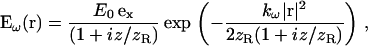
where r is the radial position, E0 is the field amplitude, kω is the fundamental wave number, z is the coordinate along the beam axis, ex is the polarization direction, 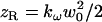 is the Rayleigh length of the focused beam (equal to half the confocal parameter), and w0 is the waist radius.
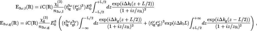
When the beam is focused on a homogeneous slice extending from z = −L/2 to z = L/2 along the optical axis (surrounded by vacuum), the third-harmonic field produced at a position R in the collection optics aperture can be expressed as (1,20,21,31)
 |
(2) |
where χ(3) is the third-order susceptibility of the sample, Δk=3kω−k3ω=6π(nω−n3ω)/λ is the wave-vector mismatch between the fundamental and the harmonic beam, nω is the sample refractive index at the fundamental frequency, n3ω is the sample refractive index at the harmonic frequency, λ is the fundamental vacuum wavelength, L is the sample thickness, and C(R) depends only on the excitation beam geometry:
 |
(3) |
The integral in Eq. 2 describes phase-matching within the sample, and reflects the fact that no TH is radiated in the far field by a homogeneous (L → ∞), normally dispersive (Δk < 0) medium. A convenient way to measure the nonlinear susceptibility χ(3) of a liquid is therefore to introduce the sample between thick calibrated glass windows (Fig. 1 b) perpendicular to the beam axis (23). The signal obtained in this geometry can be expressed as
 |
(4) |
with
 |
(5) |
where the indices g and l stand for glass and liquid, and  and
and  are transmission coefficients at the fundamental and harmonic frequency.
In the case of weak focusing (i.e., when the Rayleigh length is much greater than the coherence length of the sample: zR ≫ 2π/Δkl), the integral can be simplified because the squared Lorentzian term is slowly varying with respect to the exponential term. With the further assumption that 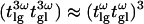 (which was verified in our conditions), one obtains the following expression for the resulting third-harmonic field:
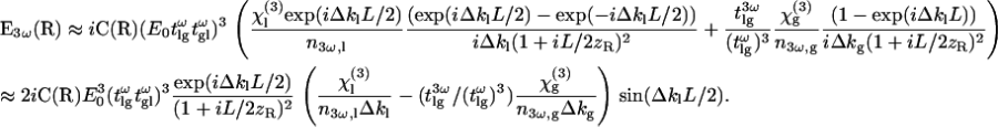 |
(6) |
Integrating the field intensity over the detector aperture (assumed large), one obtains for the total radiated third-harmonic power,
 |
(7) |
where ɛ0 is the vacuum permittivity, c is the velocity of light in vacuum, and P0 depends only on the excitation beam geometry. This equation reflects the fact that the signal exhibits a series of maxima and minima (Maker fringes) depending on the thickness L of the liquid sample. The fringe period is equal to the coherence length of the sample 2π/Δkl=λ/3(n3ω,l−nω,l), which can be used to measure the refractive index dispersion provided that one knows L. The fringe amplitude can be expressed as a product of a term P0 related to the beam properties and a second term  related to the material properties. By acquiring the THG signal successively for two different reference materials of known properties, it is possible 1), to eliminate the first, unknown term; and 2), to resolve the sign ambiguity in Eq. 7. This procedure permits an accurate determination of the properties of the sample. Finally, we note that using a pulsed excitation in the femtosecond regime results in fringe attenuation for large values of L due to dispersion of the coherence length within the pulse spectral width and to group velocity mismatch between the fundamental and harmonic pulse within the sample.
RESULTS AND DISCUSSION
Calibration of liquid optical property measurements
As pointed out by Clay et al. (9), good agreement was found among previously published measurements of third-harmonic generation by solvents with pulse-widths ranging from 30 ns to 40 fs. To validate our own measurements, we first checked the accuracy of our results on water and ethanol with respect to silica for a fundamental wavelength of 1.064 μm. Those values were established by Kajzar and Messier (35) with a precision of ∼1% using a pulsed Nd:YAG laser. To reduce measurement uncertainty, we used different water/ethanol mixtures ranging from 0 to 100% in ethanol. Given the very low absorption of both liquids around the fundamental and harmonic frequencies, we assumed a real nonlinear susceptibility. We found relative values with respect to silica of 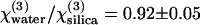 and
and  (Table 1), in very good agreement with the ratios established previously (0.90 and 1.10) (35). However, we note that these authors used values of linear indices for water (36) that differ from those usually found in handbooks (37) and an overestimated value for
  (24). We therefore propose a different absolute value for the third-order susceptibility of water
  (for λ = 1.064 μm) that takes these corrections into account and should be more accurate (see also Appendix A).
TABLE 1.
Optical properties of water and ethanol: calibration and comparison with established data at 1064 nm
| α = χ(3)/n3ω (n3ω–nω)(10−22 m2 V−2) | n3ω–nω | n3ω |  |
χ(3)(10−22 m2 V−2) | n3ω–nω* | nω* |
 * *
|
|
|---|---|---|---|---|---|---|---|---|
| Silica | 50.58†‡ | 0.0265† | 1.476† | — | 1.99‡ | 0.0265 | 1.44967 | — |
| BK7 | 61.22†‡ | 0.0315† | 1.538† | — | 2.98‡ | — | — | — |
| Water | 57.8 ± 3.9 | 0.0235† | 1.348† | 0.92 ± 0.05 | 1.83 ± 0.10 | 0.0240 | 1.32612 | 0.90 |
| Ethanol | 72.6 ± 5.1 | 0.0242† | 1.378† | 1.12 ± 0.06 | 2.42 ± 0.13 | 0.0229 | 1.33989 | 1.11 |
The nonlinear susceptibilities of water and ethanol were measured with respect to fused silica for comparison with the values reported in Kajzar and Messier (23). Updated reference data were used when determining absolute values of χ(3) (see text).
Values from Kajzar and Messier (23).
See Appendix A for the values of the linear indices used here.
χ(3) Reference values for glasses from Gubler and Bosshard (31).
Importantly, we obtained very reproducible data with only a few percent of uncertainty. This is because, in contrast with recent studies (32) where the authors focused a beam on a single interface, we performed measurements for ∼300 different liquid thicknesses times 10–15 positions along the beam direction (see Fig. 2 b). We therefore fitted the z-curve for each lateral position of the sample (corresponding to a particular thickness L), and analyzed the resulting fringe amplitude (see Fig. 2 d) according to Eq. 7. This two-step procedure eliminated artifacts due to local defects on the glass cell walls. Finally, we normalized the measurements to a reference signal, which eliminated uncertainties due to laser intensity fluctuations (see Fig. 1 a and Fig. 2, c and d). Our data for water indicates little wavelength dependence in the 1.05–1.25 μm range, and complements the measurements performed by Clay et al. in the 0.7–1.0 μm range (9). We also note that our data at 1.25 μm is 25% smaller than a recently reported value (32). However, this study used the simple z-scan geometry and neglected associated NA-induced aberrations. Correcting these data according to the analysis proposed in Pillai et al. (34) results in a value that is compatible with our measurement.
Third-order optical properties of ionic solutions
We measured the optical properties of several ionic solutions as a function of solute concentration. Our aim here was to determine whether THG microscopy may be used to probe physiological ion concentration fluctuations, as proposed in the case of intracellular calcium (15). As the nonlinear susceptibilities vary linearly with concentration for the compounds studied and in the range explored here (Fig. 3), it is possible to define the sensitivity dχ(3)/dC as the variation of χ(3) per unit of solute concentration C. The results are summarized in Table 2. It appears that the susceptibility variations with concentration are of the same order of magnitude for all compounds. As a consequence, a poor specificity of THG with respect to ion concentration variations is expected in the cellular context, where the concentration of several solutes may vary at the same time. Moreover, intracellular ionic variations generally do not exceed 1–2 mmol/L, which corresponds to χ(3) variations of <0.5% (to be compared to the ∼60% jump encountered at the glass-water interface of a microscope coverslip). As the THG signal varies as squared difference in χ(3), a 1 mmol/L variation in calcium chloride is expected to produce a TH variation four orders-of-magnitude smaller than the signal from a glass-water interface. We also investigated the wavelength dependence of χ(3) and dχ(3)/dC in the case of water and calcium chloride (see Fig. 4). The χ(3) values for silica and BK7 as a function of wavelength were taken according to the experimental formula reported in Gubler and Bosshard (31). We measured a ∼15% change in water nonlinear susceptibility over the range 1.064–1.26 μm. In contrast, we could not detect a significant variation of dχ(3)/dC for calcium chloride within this wavelength range. The fact that the sensitivity to calcium variations does not critically depend on the excitation wavelength is consistent with the absence of absorption band at the fundamental or harmonic wavelength in the range explored here.
FIGURE 3.

Optical properties of ionic solutions at 1064 nm. Measured third-order nonlinear susceptibilities of several ionic solutions as a function of solute concentration.
TABLE 2.
Variation of the nonlinear susceptibility of ionic solutions with solute concentration at 1064 nm
| dχ(3)/dC (10−22 m2 V−2 mol−1 L) | |
|---|---|
| NaCl | 0.203 ± 0.011 |
| KCl | 0.204 ± 0.011 |
| CaCl2 | 0.295 ± 0.015 |
| MgCl2 | 0.306 ± 0.017 |
| NaH2PO4 | 0.188 ± 0.021 |
| KH2PO4 | 0.196 ± 0.032 |
FIGURE 4.

Wavelength dependence of nonlinear susceptibility. (A) Measured third-order nonlinear susceptibilities of ethanol (open squares) and water (solid squares) as a function of wavelength. The dependence of the reference values used for fused silica (solid line) and BK7 glass are also shown. (B) Measured sensitivity of the third-order nonlinear susceptibility to the concentration of calcium chloride in the same wavelength range.
THG imaging of calcium concentration variations
To relate these measurements to signal variations in imaging experiments, we first performed experiments using giant unilamellar vesicles (GUVs) as a model system allowing us to control the sources of contrast. We synthesized GUVs using the electroformation method (29) in a 300 mmol/L sucrose solution and diluted them in a 300 mmol/L glucose solution. Such vesicles sedimented within a few tens of minutes at the bottom of the observation cell because of the higher density of sucrose compared to glucose, which allowed sustained imaging of individual GUVs. A weak THG signal was obtained at the GUV equator, presumably due to the slightly different optical properties of sucrose and glucose (Fig. 5 a). The signal detected at the vesicle interface rose by a factor ∼5 (Fig. 5, b and c) when a drop of a 1 mol/L calcium-chloride solution was added to the external solution, illustrating the sensitivity of the TH signal to large solute variations. However, because the external osmotic pressure was increased by the addition of calcium chloride, the vesicle collapsed within a few seconds. Although it is not possible to quantify precisely the calcium-chloride concentration at the membrane in this experiment (because the vesicles collapsed before homogenization of the external medium), we roughly estimated the concentration to be a few hundreds of mmol/L. In contrast, when a drop of a 10 mmol/L calcium chloride was added, no change in the interface signal could be detected (data not shown), as predicted by the nonlinear susceptibility measurements.
FIGURE 5.

Imaging calcium concentration changes around giant unilamellar vesicles (GUVs). (A) THG image of a sucrose-filled GUV immersed in a equimolar glucose solution (see text). (B) Same vesicle after adding a few 100 mmol/L calcium chloride in the external medium. (C) Profiles along the lines shown in panels A and B.
Homodyne detection
We investigated the possibility of homodyning the cell/external medium (em) and the coverslip signals as a means to increase the sensitivity to ion-induced χ(3) variations in cell imaging experiments. When a cell lays on a glass slide, the signal generated at the glass-cell interface is modulated by interference effects and is approximately proportional to  , where
  describes the part of the THG signal which depends on ion concentration near the cell membrane. Homodyning with the glass/em interface signal results in a linear (rather than quadratic) dependence on concentration, and is expected to provide better sensitivity to small changes.
We recorded a calibration curve by measuring the signal generated at a glass/liquid interface for different calcium-chloride concentrations (Fig. 6 a). These data indicate that a small signal variation is detectable for concentration changes on the order of 10 mmol/L. We then tried to detect similar variations near the outer membrane of cultured rat hepatocytes on glass slides. The same cells were mounted successively in 2 mmol/L, 20 mmol/L, and 50 mmol/L calcium-chloride growth medium, and images were recorded near the cell-slide interface (Fig. 6 b). Fig. 6, c and d, display typical intensity profiles obtained across individual cells for different external ion concentrations (dotted lines, 20 mmol/L; solid lines, 50 mmol/L). The THG signal did not vary significantly for moderate calcium concentration changes (2–20 mmol/L, not shown), but clear changes were visible around cell membranes when more calcium was added to the medium (20–50 mmol/L). However, the magnitude of these variations differs significantly from one cell to the other. Since THG is very sensitive to sample geometry (19), those signal variations likely result from cell shape changes (as evident from Fig. 7 c) and cannot be interpreted only in terms of ion concentration changes. From this ensemble of experiments, we conclude that THG microscopy with ∼1.2 μm excitation wavelength is not an appropriate method for imaging physiological ionic changes because of its poor specificity and sensitivity.
FIGURE 6.

Homodyne detection of ionic concentration changes around cells. (A) THG signal recorded in the microscope at a glass/liquid interface as a function of calcium-chloride concentration. (B) THG image of hepatocytes cultured on a glass slide in a solution containing 20 mmol/L calcium. (C,D) Profiles recorded along the lines indicated in panel B when the external medium contains a calcium concentration of 20 mmol/L (dashed lines) and 50 mmol/L (solid lines). Excitation wavelength is 1180 nm.
FIGURE 7.

Imaging lipid bodies in hepatocytes. (A,B) Simultaneous THG (A) and 2PEF (B) images of a hepatocyte stained with Nile Red. (C) Profile along the line indicated in panel A. (D) Three-dimensional reconstruction of the distribution of lipid bodies within the cell, from THG data.
Third-order optical properties of other aqueous solutions, lipids, and glycerol
We generalized these susceptibility measurements by characterizing χ(3) variations due to additional species in aqueous solution including amino acids, polypeptides, BSA, and glucose. Results are summarized in Table 3 and indicate that the TH signals created by physiological concentrations of molecules in aqueous solution will be generally close to that due to pure water, in the absence of χ(3) resonant enhancement. A consequence for THG imaging of cells and tissues is that large χ(3) discontinuities will be observed principally around dense inclusions consisting of molecules other than water, such as stacked proteins, crystalline or lipid structures.
TABLE 3.
Optical properties of aqueous solutions
| Type of molecule | α = χ(3)/n3ω (n3ω–nω)(10−22 m2 V−2) | χ(3) (10−22 m2 V−2) | n3ω–nω | n (633 nm) | |α–αwater|2 | dχ(3)/dC(10−22 m2 V−2 mol−1 L) | |
|---|---|---|---|---|---|---|---|
| Water | — | 61.8 ± 3.6 | 1.68 ± 0.08 | 0.0203* | 1.332* | 0 | — |
| NaCl 1 mol/L | Ions | 63.9 ± 4.2 | 1.79 ± 0.09 | 0.021 ± 0.001 | 1.344* | 4.41 | 0.11 |
| Glucose 1 mol/L | Sugar | 63.6 ± 3.7 | 1.83 ± 0.08 | 0.0212 ± 0.002 | 1.357* | 3.24 | 0.15 |
| Glycine 1 mol/L | Amino acid | 62.1 ± 5.2 | 1.69 ± 0.13 | 0.0203 | 1.332 | 0.102 | 0.01 |
| Triglycine 1 mol/L | Polypeptide | 61.9 ± 4.8 | 1.69 ± 0.12 | 0.0203 | 1.332 | 0.01 | 0.005 |
| BSA 1 mmol/L | Protein | 64.6 ± 5.1 | 1.75 ± 0.13 | 0.0203 | 1.332 | 7.91 | 0.07 |
α, χ(3), and (n3ω–nω) values are given for an excitation wavelength of 1180 nm. Variations with concentration (dχ(3)/dC) were measured at 1064 nm.
Values according to Appendix A.
Finally, we measured the optical properties of triglycerides, cholesterol, vegetable oil, and glycerol (Table 4). It appears that both the linear and nonlinear optical properties of lipid solutions greatly differ from those of water. As a result, the signal obtained from lipid droplets in tissues is expected to be 1–2 orders of magnitude higher than the one generated at an interface between two aqueous media. Interestingly, the χ(3)-related contribution to the contrast is more important than the linear contributions, which suggests that THG imaging should be more sensitive to lipid structures than imaging techniques relying on linear scattering. On the other hand, THG is not particularly sensitive to the precise lipid composition: diluting 1% cholesterol in triglycerides does not significantly modify the nonlinear susceptibility of the solution. Our measurements also show that glycerol, a common cell-mounting medium, resembles lipids in terms of nonlinear susceptibility. This has implications for THG imaging, as will be discussed below.
TABLE 4.
Optical properties of lipids and glycerol at 1180 nm and comparison with water
| α = χ(3)/n3ω (n3ω–nω)(10−22 m2 V−2) | χ(3) (10−22 m2 V−2) | |α–αwater |2 | | χ(3)–χ(3) water|2 | |
|---|---|---|---|---|
| Water | 61.8 ± 3.6 | 1.68 ± 0.08 | 0 | 0 |
| NaCl 1mol/L | 63.9 ± 4.2 | 1.79 ± 0.09 | 0.012 | 4.41 |
| Triglycerides | 83.7 ± 5.0 | 2.58 ± 0.5 | 0.8 | 480 |
| Triglycerides + cholesterol 1% | 83.7 ± 5.0 | 2.58 ± 0.5 | 0.8 | 480 |
| Vegetable oil | 90.0 ± 5.0 | 2.71 ± 0.5 | 1.1 | 795 |
| Glycerol | 85.2 ± 5.0 | 2.63 ± 0.5 | 0.9 | 550 |
THG imaging of lipid droplets in cells
In many cell types, neutral lipids such as triglycerides are stored in droplets with size ranging from a few tens of nanometers to 10–100 μm in adipocytes. For example, in hepatocytes, lipid droplets (LDs) exhibit sizes compatible with optical microscopy (0.4–10 μm). Since coherent signal enhancement occurs in THG microscopy for objects with size comparable to half the axial extent of the beam focus (18,19), and given their optical properties, hepatic LDs provide a particularly strong source of contrast in THG images, as illustrated in Fig. 7. Here, a freshly isolated rat hepatocyte was fixed and stained with Nile Red, a hydrophobic fluorescent dye specific of LDs, and imaged simultaneously with THG (Fig. 7 a) and two-photon excited fluorescence microscopies. The excellent correlation between the two images confirms that THG originates from cytoplasmic LDs. The specificity and remarkable contrast of the signal in this context are illustrated in Fig. 7 c. We point out that the ability to detect intracellular lipid structures depends on the contrast between the bulk properties of these structures and the cytoplasm. Lipid membranes per se do not provide a strong signal. For example, aqueous endosomes will generally not be visible in THG images. Also, TH signals are sensitive to linear or nonlinear susceptibility matching within the cell and may be altered by contrast agents. It was reported that acetic acid enhances the signal from nuclei in THG images of oral mucosa (14), which is likely related to the fact that this treatment changes the refractive index of nuclei (38)—and possibly their nonlinear susceptibility. Similarly, we observed that the signal from lipid structures is greatly reduced in glycerol-mounted cells (Fig. 8), which is consistent with our susceptibility measurements (Table 4).
FIGURE 8.

Influence of an index-matching medium (glycerol) on THG contrast. (A) THG image of a human epithelial cell (oral mucosa) mounted in phosphate-buffered saline. Nile Red labeling confirmed that the perinuclear bright structures are principally lipid droplets (not shown). (B) Similar cell mounted in a 33% water, 66% glycerol solution. Images are presented with the same intensity scale (inverted contrast). Scale bar is 10 μm.
CONCLUSION
We have presented quantitative measurements of χ(3) and dχ(3)/dC for a variety of biological solutions in the 1.05–1.25 μm excitation range, relevant for THG microscopy. These data help in understanding the mechanisms and sources of signal in cells and tissues, which is essential for further development of THG microscopy in biology. We chose to concentrate on this spectral range because it minimizes one- and two-photon absorption in most biological samples, which in turn minimizes potential photodamage (while allowing detection in the visible region of the spectrum). Avoiding absorption may be critical for sustained imaging of live cells because THG is a weak process, and rapid imaging typically requires higher intensities than what is commonly used for 2PEF imaging with 800–900 nm excitation. Under such conditions, previous studies showed that THG microscopy preserves cell viability and activity (5), and that it can be used to study the dynamics of embryo morphogenesis without perturbation (11).
Our data show that aqueous solutions at physiological concentrations are generally close to pure water and do not provide strong nonlinear contrast. In particular, we have shown that in the range 1.05–1.25 μm, calcium imaging with THG microscopy is not practical due to low sensitivity and poor selectivity. Even in the case of homodyne detection, signal changes can be attributed principally to geometrical changes rather than to ion fluxes. Instead, THG from unstained cells and tissues will be obtained at the interface of dense, nonaqueous structures. One such source of contrast is lipid droplets, because the nonlinear susceptibility of lipids differs significantly from water. Provided that their size is large enough to allow for coherent signal buildup, lipid droplets can be imaged within rapid acquisition times in specialized cells such as hepatocytes. The ability to detect these structures opens an interesting field of application for THG microscopy, because few other methodologies can be used to track lipid bodies in intact tissues.
We note that other dense inclusions can provide a source of contrast in biological THG imaging. An interesting example is crystalline mineral structures such as sea urchin spicules, where birefringence can be exploited to force phase-matching (3). Also, tuning the excitation wavelength close to a one-, two-, or three-photon resonance may result in a specific χ(3) increase that can be exploited to detect other structures, provided that their organization and geometry is favorable for THG. This may account for the strong signal obtained from chloroplasts (2), and for mitochondria-related signals (16). However, caution should be taken when using resonantly enhanced THG as a contrast mechanism because routes for phototoxicity (production of reactive oxygen species, etc.) may also be favored under these conditions.
In conclusion, the data reported in this study provide a basis for the quantitative interpretation of biological THG images and for developing additional applications.
Acknowledgments
We thank M. Joffre and F. Hache for helpful discussions, and L. Combettes for providing us with the hepatocytes.
This work was supported by the Délégation Générale pour l'Armement.
APPENDIX A: LINEAR INDICES FOR WATER, ETHANOL, AND GLASS USED IN THIS STUDY
Values of the refractive index (n) of water as a function of wavelength (λ in nm) were obtained by combining data from references (37,39–45). Data were fitted by a Cauchy formula according to n(λ) = P1 + P2λ2 + P3λ−2 + P4λ−4 + P5λ−6 with coefficients P1 = 1.32614 ± 0.00024, P2 = −3.1944 × 10⁻⁹ ± 2.0559 × 10⁻¹⁰, P3 = 2.746 × 10³ ± 72.3, P4 = −5.2079 × 10⁵ ± 6.7946 × 10⁶, and P5 = 1.7581 × 10¹² ± 1.9465 × 10¹¹.
Values of the refractive index of ethanol as a function of wavelength were obtained in the same manner by fitting data from the literature (37,39,41,42,44,45) by a Cauchy formula with coefficients P1 = 1.35434 ± 0.00126, P2 = −2.5857 × 10⁻⁹ ± 1.1851 × 10⁻⁹, P3 = 2.8836 × 10³ ± 355.89, P4 = 2.78187 × 10⁶ ± 3.3047 × 10⁷, and P5 = 2.1666 × 10¹² ± 9.40072 × 10¹¹.
Refractive indices for fused silica and BK7 were calculated from Sellmeier's formula (see, e.g., (9)). The index used for tryglycerides at 633 nm was 1.465 (European standard for triacetin). The index used for olive oil at 633 nm was 1.435 (French standard). In both cases, index dispersion was estimated from the period of the Maker fringes.
References
- 1.Barad, Y., H. Eisenberg, M. Horowitz, and Y. Silberberg. 1997. Nonlinear scanning laser microscopy by third harmonic generation. Appl. Phys. Lett. 70:922–924. [Google Scholar]
- 2.Müller, M., J. Squier, K. R. Wilson, and G. J. Brakenhoff. 1998. 3D-microscopy of transparent objects using third-harmonic generation. J. Microsc. 191:266–274. [DOI] [PubMed] [Google Scholar]
- 3.Oron, D., D. Yelin, E. Tal, S. Raz, R. Fachima, and Y. Silberberg. 2004. Depth-resolved structural imaging by third-harmonic generation microscopy. J. Struct. Biol. 147:3–11. [DOI] [PubMed] [Google Scholar]
- 4.Chu, S.-W., I.-H. Chen, T.-M. Liu, P.-C. Chen, and C.-K. Sun. 2001. Multimodal nonlinear spectral microscopy based on a femtosecond Cr:Forsterite laser. Opt. Lett. 26:1909–1911. [DOI] [PubMed] [Google Scholar]
- 5.Débarre, D., W. Supatto, A.-M. Pena, A. Fabre, T. Tordjmann, L. Combettes, M.-C. Schanne-Klein, and E. Beaurepaire. 2006. Imaging lipid bodies in cells and tissues using third-harmonic generation microscopy. Nat. Methods. 3:47–53. [DOI] [PubMed] [Google Scholar]
- 6.Squier, J. A., and M. Müller. 1999. Third-harmonic generation imaging of laser-induced breakdown in glass. Appl. Opt. 38:5789–5794. [DOI] [PubMed] [Google Scholar]
- 7.Supatto, W., D. Debarre, B. Moulia, E. Brouzes, J. L. Martin, E. Farge, and E. Beaurepaire. 2005. In vivo modulation of morphogenetic movements in Drosophila embryos with femtosecond laser pulses. Proc. Natl. Acad. Sci. USA. 102:1047–1052. [DOI] [PMC free article] [PubMed] [Google Scholar]
- 8.Yelin, D., and Y. Silberberg. 1999. Laser scanning third-harmonic generation microscopy in biology. Opt. Expr. 5:169–175. [DOI] [PubMed] [Google Scholar]
- 9.Clay, G. O., A. C. Millard, C. B. Schaffer, J. Aus-der-Au, P. S. Tsai, J. A. Squier, and D. Kleinfeld. 2006. Spectroscopy of third harmonic generation: evidence for resonances in model compounds and ligated hemoglobin. J. Opt. Soc. Am. B. 23:932–950. [Google Scholar]
- 10.Schaller, R. D., J. C. Johnson, K. W. Wilson, L. F. Lee, L. H. Haber, and R. J. Saykally. 2002. Nonlinear chemical imaging nanomicroscopy: from second and third harmonic generation to multiplex (broad-bandwidth) sum frequency generation near-field scanning optical microscopy. J. Phys. Chem. B. 106:5143–5154. [Google Scholar]
- 11.Débarre, D., W. Supatto, E. Farge, B. Moulia, M.-C. Schanne-Klein, and E. Beaurepaire. 2004. Velocimetric third-harmonic generation microscopy: micrometer-scale quantification of morphogenetic movements in unstained embryos. Opt. Lett. 29:2881–2883. [DOI] [PubMed] [Google Scholar]
- 12.Sun, C.-K., S.-W. Chu, S.-Y. Chen, T.-H. Tsai, T.-M. Liu, C.-Y. Lin, and H.-J. Tsai. 2004. Higher harmonic generation microscopy for developmental biology. J. Struct. Biol. 147:19–30. [DOI] [PubMed] [Google Scholar]
- 13.Sun, C.-K., C.-C. Chen, S.-W. Chu, T.-H. Tsai, Y.-C. Chen, and B.-L. Lin. 2003. Multiharmonic generation biopsy of skin. Opt. Lett. 28:2488–2490. [DOI] [PubMed] [Google Scholar]
- 14.Tai, S.-P., W.-J. Lee, D.-B. Shieh, P.-C. Wu, H.-Y. Huang, C.-H. Yu, and C.-K. Sun. 2006. In vivo optical biopsy of hamster oral cavity with epi-third-harmonic generation microscopy. Opt. Express. 14:6178–6187. [DOI] [PubMed] [Google Scholar]
- 15.Canioni, L., S. Rivet, L. Sarger, R. Barille, P. Vacher, and P. Voisin. 2001. Imaging of Ca2+ intracellular dynamics with a third-harmonic generation microscope. Opt. Lett. 26:515–517. [DOI] [PubMed] [Google Scholar]
- 16.Barzda, V., C. Greenhalgh, J. Aus-der-Au, and S. Elmore. 2006. Visualization of mitochondria in cardiomyocytes by simultaneous harmonic generation and fluorescence microscopy. Opt. Express. 13:8263–8276. [DOI] [PubMed] [Google Scholar]
- 17.Schins, J. M., T. Schrama, J. Squier, G. J. Brakenhoff, and M. Müller. 2002. Determination of material properties by use of third-harmonic generation microscopy. J. Opt. Soc. Am. B. 19:1627–1634. [Google Scholar]
- 18.Cheng, J.-X., and X. S. Xie. 2002. Green's function formulation for third harmonic generation microscopy. J. Opt. Soc. Am. B. 19:1604–1610. [Google Scholar]
- 19.Débarre, D., W. Supatto, and E. Beaurepaire. 2005. Structure sensitivity in third-harmonic generation microscopy. Opt. Lett. 30:2134–2136. [DOI] [PubMed] [Google Scholar]
- 20.Ward, J. F., and G. H. C. New. 1969. Optical third-harmonic generation in gases by a focused laser beam. Phys. Rev. 185:57–72. [Google Scholar]
- 21.Boyd, R. W. 2003. Nonlinear Optics, 2nd Ed. Academic Press, NY.
- 22.Chen, I.-H., S.-W. Chu, C.-K. Sun, P.-C. Cheng, and B.-L. Lin. 2002. Wavelength-dependent damage in biological multiphoton confocal microscopy: a micro-spectroscopic comparison between femtosecond Ti:Sapphire and Cr:Forsterite laser sources. Opt. Quant. Electron. 34:1251–1266. [Google Scholar]
- 23.Kajzar, F., and J. Messier. 1987. Original technique for third-harmonic-generation measurements in liquids. Rev. Sci. Instr. 58:2081–2085. [Google Scholar]
- 24.Bosshard, C., U. Gubler, P. Kaatz, W. Mazerant, and U. Meir. 2000. Non-phase-matched optical third-harmonic generation in noncentrosymmetric media: cascaded second-order contributions for the calibration of third-order nonlinearities. Phys. Rev. B. 61:10688–10701. [Google Scholar]
- 25.Stoker, D., M. F. Becker, and J. W. Keto. 2005. Optical third-harmonic generation from ultrashort laser pulses. Phys. Rev. A. 71:061802. [Google Scholar]
- 26.Stoker, D. S., J. Baeck, W. Wang, D. Kovar, M. F. Becker, and J. W. Keto. 2006. Ultrafast third-harmonic generation from textured aluminum nitride-sapphire interfaces. Phys. Rev. A. 73:053812. [Google Scholar]
- 27.Tasgal, R. S., and Y. B. Band. 2004. Third-harmonic generation in isotropic media by focused pulses. Phys. Rev. A. 70:053810. [Google Scholar]
- 28.Tordjmann, T., B. Berthon, M. Claret, and L. Combettes. 1997. Coordinated intercellular calcium waves induced by noradrenaline in rat hepatocytes: dual control by gap junction permeability and agonist. EMBO J. 16:5398–5407. [DOI] [PMC free article] [PubMed] [Google Scholar]
- 29.Angelova, M. I., S. Soléau, P. Méléard, J. F. Faucon, and P. Bothorel. 1992. Preparation of giant vesicles by external AC fields. Kinetics and applications. Prog. Colloid Polym. Sci. 89:127–131. [Google Scholar]
- 30.Meredith, G. R., B. Buchalter, and C. Hanzlik. 1983. Third-order optical susceptibility determination by third-harmonic generation. J. Chem. Phys. 78:1533–1551. [Google Scholar]
- 31.Gubler, U., and C. Bosshard. 2000. Optical third-harmonic generation of fused silica in gas atmosphere: absolute value of the third-order nonlinear susceptibility χ(3). Phys. Rev. B. 61:10702–10710. [Google Scholar]
- 32.Schcheslavskiy, V., G. I. Petrov, S. Saltiel, and V. V. Yakovlev. 2004. Quantitative characterization of aqueous solutions probed by the third-harmonic generation microscopy. J. Struct. Biol. 147:42–49. [DOI] [PubMed] [Google Scholar]
- 33.Barille, R., L. Canioni, L. Sarger, and G. Rivoire. 2002. Nonlinearity measurements of thin films by third-harmonic generation microscopy. Phys. Rev. E. 66:067062. [DOI] [PubMed] [Google Scholar]
- 34.Pillai, R. S., G. J. Brakenhoff, and M. Müller. 2006. Analysis of the influence of spherical aberration from focusing through a dielectric slab in quantitative nonlinear susceptibility measurements using third-harmonic generation. Opt. Express. 14:260–269. [DOI] [PubMed] [Google Scholar]
- 35.Kajzar, F., and J. Messier. 1985. Third-harmonic generation in liquids. Phys. Rev. A. 32:2352–2363. [DOI] [PubMed] [Google Scholar]
- 36.Hellwarth, R. W. 1977. Third-order optical susceptibilities of liquids and solids. Prog. Quantum Electron. 5:1–68. [Google Scholar]
- 37.Landolt-Börnstein. 1974. Numerical Data and Functional Relationships in Science and Technology. Springer, NY.
- 38.Rajadhyaksha, M., S. Gonzalez, and J. M. Zavislan. 2004. Detectability of contrast agents for confocal reflectance imaging of skin and microcirculation. J. Biomed. Opt. 9:323–331. [DOI] [PubMed] [Google Scholar]
- 39.Lide, D. R. 2003. Handbook of Chemistry and Physics, 84th Ed. CRC Press, Boca Raton, FL.
- 40.Halle, G. M., and M. R. Querry. 1973. Optical constants of water in 200-nm to 200-mm wavelength region. Appl. Opt. 12:555–563. [DOI] [PubMed] [Google Scholar]
- 41.Moreels, E., C. Degreef, and R. Finsy. 1984. Laser-light refractometer. Appl. Opt. 42:3010–3013. [DOI] [PubMed] [Google Scholar]
- 42.Nemoto, S. 1992. Measurement of the refractive index of liquid using laser-beam displacement. Appl. Opt. 31:6690–6694. [DOI] [PubMed] [Google Scholar]
- 43.Nikogosyan, N. D. 1997. Properties of Optical and Laser-Related Materials: a Handbook. Wiley, NY.
- 44.Rheims, J., J. Koser, and T. Wriedt. 1997. Refractive-index measurements in the near-IR using an Abbe refractometer. Meas. Sci. Technol. 8:601–605. [Google Scholar]
- 45.Sainov, S., Y. Sarov, and S. Kurtev. 2003. Wide spectral-range laser refractometer. Appl. Opt. 42:2327–2328. [DOI] [PubMed] [Google Scholar]