Abstract
A microfluidic platform for the construction of microscale components and autonomous systems is presented. The platform combines liquid-phase photopolymerization, lithography, and laminar flow to allow the creation of complex and autonomous microfluidic systems. The fabrication of channels, actuators, valves, sensors, and systems is demonstrated. Construction times can be as short as 10 min, providing ultrarapid prototyping of microfluidic systems.
Construction of microscale systems generally has been approached from two perspectives. Either the components are fabricated separately and then assembled (as at the macroscale) or lithography-based microfabrication methods are used to create the components at their desired locations (e.g., polysilicon surface micromachining). Assembly of micrometer-sized objects has proven to be nontrivial because electrostatic and other surface forces are overwhelming at the microscale, making manipulation difficult (1). Through appropriate geometric design, these forces can be harnessed to self-assemble small parts (2). Conventional lithographic approaches show promise, but the many disparate materials and processes hinder the fabrication of complex systems. For example, the processes used to construct one system component (e.g., a sensor) may be incompatible with those for other components (e.g., pumps and valves). To realize microscale systems for many different applications, unconventional approaches are needed to overcome these difficulties. The physics of scaling (i.e., laminar flow, high surface-to-volume ratio) can lead to significantly improved performance in some medical and biological applications and also allow for in-channel construction. Whitesides and coworkers (3) have demonstrated several in-channel fabrication techniques that use laminar flow to create textured walls and to build metal traces within microchannels. Smela et al. (4) demonstrated conductive microscale actuators built on flat substrates by patterning conductive polymers using lithography. Two-photon polymerization has been used to create three-dimensional (3D) structures from a polymer gel precursor (5, 6).
Previously, we reported the ability to build in-channel autonomous hydrogel valves by using a photopolymerization process (7). It has been demonstrated that stimuli-responsive hydrogels are the natural materials for microfluidic systems in terms of scaling physics because smaller size leads to faster volume changes for these diffusion-controlled processes. Here, we expand this photopolymerization method to a fabrication platform for total system construction. This fabrication platform, which we refer to as microfluidic tectonics (μFT), utilizes microfluidics, photopolymerization, and materials chemistry to create autonomous microfluidic systems controlled by the local fluidic environment. μFT allows one to develop a wide variety of microfluidic systems by using one common construction platform, providing several key advantages. First, it provides a general, integrated platform for the construction of all system structures and components. This is a departure from traditional approaches, which require a wide range of materials and sensing/actuation technologies, making integration costly and difficult. Second, the hydrogels function as both sensor and actuator, providing a stand-alone detection/readout component that links a microscale event (sensing of local fluid environment) to a macroscale response (volume change), thereby eliminating the need for complicated instrumentation (sensors and electronics). Finally, the platform can be adapted to manufacture different components for carrying out a variety of system functions (filtering, separation, mixing, etc.) while incorporating local autonomous control of chemistry, flow, and other parameters.
Methods and Results
μFT integrates liquid-phase photopolymerization, lithography, and laminar flow to build autonomous microfluidic systems (Fig. 1). The construction of a μFT system starts with a universal cartridge. The method then employs photomasks, a light source, and photopolymerizable prepolymer mixtures of both structural (nonfunctional) and functional (stimuli-responsive) materials. Micromolding techniques are used to produce the universal cartridges that include a wide, shallow fluid reservoir serving as blank slates. Polymer components (both functional and structural) are created inside the cartridge via direct photopatterning of a liquid-phase prepolymer mixture. Through the application of liquid-phase polymerization, lithography, and laminar flow, all system components including the microchannels are constructed easily by using μFT.
Figure 1.
Overview of μFT. The fabrication of a hydrogel jacket valve in a T channel is illustrated as an example in the schematics. (A) After the reservoir is filled with the prepolymer mixture of a structural material (blue), it is exposed to UV light through a photomask. (B) After flushing away the unpolymerized mixture, a T channel and a cylindrical post were fabricated in parallel. (C) After the T channel is filled with the prepolymer mixture of a stimuli-responsive hydrogel (green), it is exposed to UV light again through a second photomask. (D) After removing the unpolymerized mixture, a hydrogel jacket valve is fabricated within a T channel. Channel fabrication and component fabrication are combined via parallel or sequential polymerization to build a functional complex system.
In a typical procedure, a fluid reservoir ranging from 100 to 250 μm deep and 500 to 25,000 μm wide is filled with a prepolymer mixture consisting of monomers and a photoinitiator. The mixture is allowed to reach a quiescent state and then exposed to UV light through a photomask placed on top of the cartridge. Polymerization times typically range from 5 sec to 10 min depending on the photoinitiator, monomer mixture, and light intensity. A convenient light source is the filtered light source from a standard fluorescence microscope. When the polymerization is complete, the channel is flushed with suitable solvent (e.g., water, methanol, etc.) to remove the unpolymerized liquid. Multiple structures can be created simultaneously by using a photomask with a multistructure pattern (parallel polymerization) or by refilling the fluid reservoir with another prepolymer mixture and repeating the polymerization in a sequential fashion (sequential polymerization). Objects that are close together (<250 μm) cannot be fabricated simultaneously because partial polymerization occurs between the objects. The partially polymerized mixture cannot be removed easily by flushing the channel. Therefore, sequential polymerization needs to be used to solve this problem. Objects with a spacing of 100 μm have been made. The combination of parallel and sequential polymerization allows polymer components of different materials, shapes, and sizes (illustrated in Fig. 2) to be integrated directly into microfluidic systems.
Figure 2.
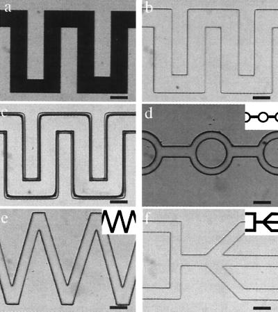
Construction of microchannels using μFT. The monomer mixture consists of IBA, TeEGDMA (5 wt %), and Irgacure 651 (3 wt %). (a– c) Basic procedures. (a) Photomask placed on top of the channel. (b) After photopolymerization. (c) After removing the unpolymerized monomer mixture with MeOH. (d– f) A variety of possible channel geometries with the corresponding photomask shown at a reduced size in the upper right corner of each picture. (Bars = 500 μm.)
Fig. 2 illustrates the basic procedures and example geometries of microchannel construction. The structural material normally consists of a mixture of isobornyl acrylate (IBA), 2,2-bis[p-(2′-hydroxy-3′-methacryloxypropoxy)phenylene]propane or tetraethyleneglycol dimethacrylate (TeEGDMA), and Irgacure 651 as photoinitiator. These monomers have two advantages: low degree of shrinkage during polymerization and fast polymerization kinetics. Typical polymerization times range from 5 to 40 sec. After UV exposure, the liquid prepolymer mixture turns into a clear, rigid material. By adjusting the monomer composition, microchannels resistant to a variety of common solvents (e.g., water, ethanol, and acetone) can be made.
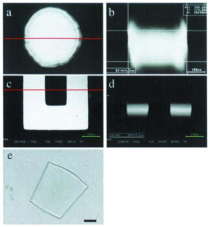
Resolution is limited by both optical and chemical effects. Typically, light scattering and reflections enlarge the base of the image in a negative resist in traditional photolithography. The line widths continue to enlarge with exposure time. The photopolymerizable liquid used here can be thought of as a liquid-phase negative resist. The polymerization of relatively deep liquid-phase mixtures introduces other effects, including the depth of focus of the exposing light, diffusion during polymerization, and different optical properties between the liquid phase and the polymer. Perfect collimation is not achieved in the microscope and contact aligner used for exposure. Thus, a few degrees of divergence exist and are most significant in deep (150–300 μm) channels. The divergence effect appears to be more prominent in hydrogel polymerization than scattering and reflection. The interplay of optical, material, and diffusion effects has not been analyzed fully yet. The side wall profiles normally vary from near-vertical to, at most, 10% variance (top to bottom), as shown by the photograph and confocal images in Fig. 3. For many applications, these tolerances are acceptable.
Figure 3.
Confocal images and photograph showing nonvertical side walls. (a and b) Confocal images of the top and the cross-section (along the line) of a cylindrical hydrogel object polymerized in a 180-μm-deep microchannel. A fluorescent dye was trapped inside the hydrogel for visualization purposes. b reveals a slightly tapered shape with a smaller diameter at the bottom than the top. (c and d) Confocal images of the top and the cross-section of an in situ fabricated microchannel filled with a fluorescent dye solution. d suggests near-vertical side walls with a slightly smaller channel width at the bottom than the top. (e) The photograph of a hydrogel object that flipped over during expansion. The hydrogel showed side walls that deviated from the surface normal by ≈6°. (Bar = 250 μm.)
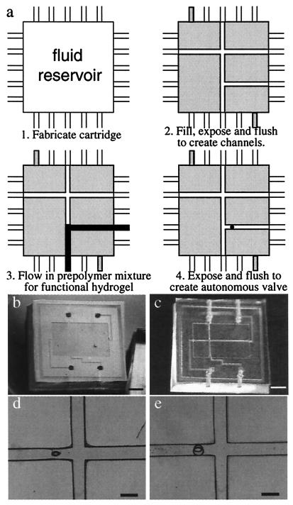
A microfluidic system containing multiple channels and an autonomous valve has been constructed by using the μFT process. The system includes a T junction, a straight channel, and an injection channel controlled by an autonomous hydrogel valve. Fig. 4 illustrates (both schematically and experimentally) the steps required to build a functional microfluidic system by using μFT. A polydimethylsiloxane (PDMS)/glass cartridge first is injected with a prepolymer mixture of the construction material through the inlet channel by using a syringe. Cartridge filling is facilitated by making the chamber hydrophilic (either via chemical or plasma treatment). The prepolymer mixture then is polymerized through a photomask, which defines the channel pattern as well as a poststructure in the injection channel. The unexposed region then is flushed with water to remove the unpolymerized mixture, revealing the desired channel pattern and the post (Fig. 4 C and D). Next, a second (functional) prepolymer mixture is injected into the newly formed microchannels, and the mixture is exposed to a UV source from an Olympus Epi-Fluorescent microscope (Olympus, New Hyde Park, NY) for 5 min through a patterned photomask (300-μm hole) aligned over the previously formed post. By controlling the pressures on all inputs/outputs, the functional prepolymer mixture can fill specific channels as desired. After removing the unexposed mixture by flushing with water, a pH-sensitive hydrogel valve jackets the post. As is evident from Fig. 4, the μFT construction method allows rapid fabrication with a high degree of design freedom. The time required to build the system shown is less than 10 min when using the previously prepared cartridge and photomask. Both sequential and parallel polymerization are used in this demonstration to simplify the fabrication. We envision that the process can be simplified further by replacing the physical photomask with a light array.
Figure 4.
System construction using μFT. (a) A schematic of the steps to fabricate a functional microfluidic system using μFT. (b) The PDMS/glass tectonics cartridge. PDMS substrate with a shallow and wide fluidic chamber (i.e., Tectonics cartridge; 12-mm ×18-mm wide, 200-μm deep) was molded in a Petri dish by using a positive relief master. The inlet/outlet connection channels were cored through the side of the block to retain complete optical access over the entire cartridge. A microscope cover glass was bonded to the PDMS substrate as the cartridge top after activating the surface with oxygen plasma in an reactive ion etch system. (c and d) The tectonics cartridge after simultaneous fabrication of a microchannel and a post using a multipattern photomask. The prepolymer mixture for this construction material consists of IBA and TeEGDMA (in a 9:1 weight ratio) and Irgacure 651 (3.0 wt %). The UV source is a 200-W mercury lamp (≈400 mJ/cm2), and the exposure time is 1 min. (e) The pH-sensitive hydrogel jacket around the post after exposure and flushing. The prepolymer mixture for this pH-sensitive hydrogel consists of acrylic acid and 2-hydroxyethyl methacrylate (HEMA) (in a 1:4 molar ratio), ethyleneglycol dimethacrylate (EGDMA, 1.0 wt %), and Irgacure 651 (3.0 wt %). [Bars = 5,000 μm (b and c) and 500 μm (d and e).]
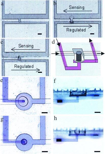
To create useful, functionally complex microfluidic systems, flow control is required. Several hydrogel valve designs have been demonstrated, ranging from simple two-dimensional designs to hybrid (PDMS/hydrogel) 3D designs, to biomimetic designs based on two different material beams. In the most basic configuration, a single hydrogel cylinder is formed by using the photopolymerization methods described above. The hydrogel regulates the flow by expanding or contracting to seal or open the channel. These single-channel valve designs will be useful in many applications. However, it also would be beneficial to be able to sense the local environment in one channel and regulate the flow in another channel. We have developed two valve schemes to accomplish this goal. In the first case, a hydrogel plug is polymerized in a gap between two adjacent parallel channels. Through appropriate placement and relative channel dimensions, the hydrogel responds to the pH in the sensing channel and controls the flow in the regulated channel by either contracting or expanding (Fig. 5 a–c). One of the limitations of the above hydrogel valve design is the potential for cross-talk between channels because of diffusion of species of interest through the hydrogel itself. To address this problem, we developed a hybrid PDMS/hydrogel valve by combining 3D PDMS fabrication (8) and in situ polymerization techniques (Fig. 5 d–h). A PDMS membrane (ion-impermeable) was created between the sensing and regulated flow streams with a pH-sensitive hydrogel on top of it that deflects the PDMS membrane when swollen. The deflection causes the membrane to seal against the orifice below it, blocking flow. The maximum differential pressures were 50 psi for the postjacket valve design (limited by an off-chip connection failure) and 27 psi for the hybrid valve design when they are closed. The valves have been operated for hundreds of cycles without failure. Force generation in the hybrid valve is estimated via analytical models to be more than 20 mN.
Figure 5.
Hydrogel valve designs. (a– c) A two-dimensional hydrogel valve design. (a) A hydrogel plug is polymerized in the gap between two adjacent parallel channels. The hydrogel composition is the same as that described in Fig. 4e, with a pH volume transition at pH = 5. The sensing channel (600-μm wide) was constructed wider than the regulated channel (300-μm wide) to keep the sensing channel open when the regulated channel is completely shut off. The microchannel is made of EPON (Nano XP SU-8 50; Microchem, Newton, MA). Transparent adhesive tape (regular packaging tape) was used to seal the 200-μm-deep EPON microchannels. (b) A pH 5.7 buffer is pumped through the sensing channel while water is pumped through the regulated channel. The hydrogel valve expands to seal off the flow in the regulated channel. The arrows denote the direction of the fluid flow. (c) The valve reopens the regulated channel when a pH 3.8 solution was pumped through the sensing channel. (d– h) A 3D PDMS/hydrogel hybrid valve design. (d) A schematic of the PDMS/hydrogel hybrid valve. (e and f) The top view and the side view of the hydrogel structure when it expands and deforms a membrane, blocking the flow in an adjacent channel. The fluid in the blocked channel has been dyed for visualization purposes. (g and h) The hydrogel valve contracts, and the membrane returns to a position that allows flow in the adjacent channel. [Bars = 400 μm (a– c) and 250 μm (e– h).] Note in the side views that the edge of the hydrogel actuator has been outlined for clarity.
To further improve the time response of the functional hydrogel valve, two approaches have been demonstrated. The first is a post-jacket design (7), which improves the time response by reducing the diffusion distance required for complete volume changes. In addition to modifying the geometry of the hydrogel objects, porosity can be introduced to the hydrogel structure to speed up the diffusion process. The introduction of porosity is achieved by inducing phase separation during polymerization. It is observed that the step response improves more than 10-fold for both swelling and shrinking processes upon such modification.
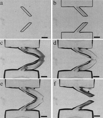
Construction of other devices and components can be realized by using our approach. For example, by combining two strips of hydrogel material with different pH sensitivity, a shape-changing structure that bends in response to changes in local pH has been demonstrated. In a typical procedure, after polymerizing a strip of pH-sensitive hydrogel, the channel is flushed and filled with a non-pH-sensitive monomer mixture. A strip of non-pH-sensitive hydrogel is then polymerized at an adjacent location, slightly overlapping with the previous hydrogel strip. The non-pH-sensitive hydrogel strip also has an anchor that fixes one end of the bistrip hydrogel to the channel top and bottom at the desired location. When exposed to a basic solution, the pH-sensitive strip swells whereas the other strip remains the same volume, causing the bistrip gel to curve toward the non-pH-sensitive strip. A biomimetic check valve based on such a bistrip hydrogel is demonstrated in Fig. 6. When triggered by high pH, the pair of bistrip hydrogels extends and bends to close the channel. In this way, it operates as the passive valves found in veins, allowing the fluid flow in only one direction. The pH-sensitive strip serves as a spring to provide a restoring force for the valve. When contracted in acidic solution, the valve becomes deactivated and remains permanently open (Fig. 6f). In this example, the valve responds to the local chemical environment in addition to the local fluid flow characteristics.
Figure 6.
A biomimetic valve based on bistrip hydrogel. (a) After simultaneous polymerization of the pH-sensitive strips. The hydrogel composition is the same as that described in Fig. 4e. (b) After polymerization of the non-pH-sensitive strips to form the bistrip hydrogel valve with anchor. The prepolymer mixture for the non-pH-sensitive hydrogel consists of HEMA, EGDMA (1.0 wt %), and Irgacure 651 (3.0 wt %). (c) When exposed to basic solution, the bistrip hydrogel expands and curves to form a normally closed valve. The bistrip valve can be pushed open (d) to allow flow in one direction (from left to right) while restricting flow in the opposite direction (e). (f) When exposed to acidic solutions, the valve is deactivated, returning to the permanently open state. (Bars = 500 μm.)
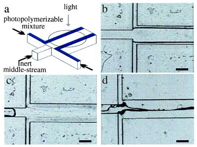
Finally, laminar flow (without photomasks) can be used to control geometry during fabrication as illustrated in Fig. 7. In this case, three fluid streams are pumped through a microchannel. The two outer streams contain functional prepolymer mixtures, and the middle stream consists of an inert fluid. After steady laminar flows are established by using syringe pumps, the flow rates are gradually reduced to zero followed by immediate UV irradiation at the desired area to initiate polymerization. The result of polymerization is the formation of pH-sensitive hydrogels along the edges of the channel. These walls subsequently can be used to regulate flow based on the pH value of the fluid. By incorporating laminar flow, it may be possible to realize 3D fabrication by using μFT. In addition, components made of different materials that are otherwise incompatible can be fabricated simultaneously by using this method because the inert stream eliminates the necessity of direct contact between the two outer streams.
Figure 7.
Geometry control during fabrication by using laminar flows. (a) A schematic of the fabrication method using laminar flows to control geometry. (b) Steady laminar flows are obtained before UV irradiation. The outer streams of prepolymer mixture contain acrylic acid, EGDMA, water, and a photoinitiator. The middle stream consists of glycerin. The channel fabrication is the same as described in Fig. 5a. (c) After UV irradiation for 2 min, pH-sensitive hydrogel walls are formed while the center of the channel remains open. (d) When exposed to a basic solution, the pH-sensitive hydrogels expand to seal off the channel. (Bars = 500 μm.)
Biosensing is another area of interest in microfluidics. By using the μFT method, we have modified hydrogels with lipid or fatty acid coatings that will be the foundation of a new class of biosensor devices (9). In an ideal design, this approach will consist of a pH-sensitive hydrogel matrix modified on its surface with a lipid bilayer that contains channel proteins or receptors. As such, we call this type of component a “cell gel.” Because the lipid coating is impermeable to ions, a different pH can be maintained within the hydrogel interior, allowing the hydrogel to remain contracted while bathed in a pH environment that normally would cause volume expansion. Upon exposure to a membrane-disrupting agent, the lipid bilayer will leak, causing the hydrogel to swell and, thereby, amplifying the original signal.
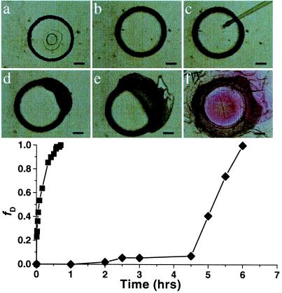
We have completed the preliminary steps of this approach. First, a pH-sensitive hydrogel containing a pH indicator (phenolphthalein) is polymerized in a microchannel by using the above technique. The hydrogel then is bathed in benzene and modified by covalently linking fatty acids to the surface. Finally, the modified hydrogel is exposed to a basic solution (which normally would cause the hydrogel to swell) and the hydrogel diameter is measured at timed increments to test the efficiency of the fatty acid layer as an ion barrier. It was found that hydrogels modified in this manner remain stable for a several days without visible change in color or size, demonstrating the ability to maintain chemical gradients. In contrast, unmodified hydrogels that contain the pH indicator (phenolphthalein) become fully expanded within 40 min along with a color change from clear to pink. The modified hydrogels are capable of swelling and changing color once the fatty acid layer is physically disrupted, as illustrated in Fig. 8. When exposed to a buffer solution with a pH of 12, a modified hydrogel shows no change until the fatty acid layer was physically disrupted by piercing the gel with a micropipette tip, causing the gel to rapidly swell and change color.
Figure 8.
A pH-sensitive hydrogel modified with a fatty acid surface layer. A cylindrical hydrogel with a diameter of 400 μm is polymerized in a microchannel. The hydrogel material is the same as described in Fig. 4e, which contains hydroxyl termini. Fatty acid segments then are covalently linked to the hydroxyl groups on the outer surface of the hydrogel via in-channel treatment (a). When a pH = 12 buffer is flowed through the channel, the modified hydrogel (♦) remains stable for hours without obvious change (b), whereas an unmodified hydrogel of the same composition and size (■) starts to swell instantly. After piercing the hydrogel with a micropipette tip to physically disrupt the surface layer (c), the modified hydrogel starts to swell at the pierced location (d and e) and eventually becomes fully swollen accompanied by a color change (f). (Bars = 100 μm.)
Discussion
μFT offers an alternative approach to microfluidic system fabrication. The combination of liquid-phase polymerization, lithography, and laminar flow provides a universal construction platform that allows for continued growth and expansion in the design parameter space. The construction platform, components, and systems described in this paper demonstrate the versatility of the approach.
A variety of materials can be used within the fabrication processes, including both nonfunctional construction materials and stimuli-responsive hydrogels. Known functionality includes response to stimuli such as pH, temperature, electric fields, light, carbohydrates, and antigens. Thus, functionally complex systems can be fabricated by using a single construction platform. The performance of the hydrogel components in terms of displacement and force generation are excellent, and the observed temporal response is one to two orders of magnitude better than typical macroscopic hydrogel structures because of scaling. Further improvements through chemical modification also have been achieved, which will lead to rapid sensing and actuating in many microfluidic systems.
New materials can be developed to add new functionality. As described above, we recently have demonstrated a hydrogel/fatty acid layer hybrid component that will serve as the basis of a class of biosensor components. The goal of this class of biosensor components is to capture nature's exquisite ability to detect signals with high sensitivity and specificity without the limitations of cell-based biosensors. By incorporating molecular recognition structures (e.g., transmembrane proteins) within the lipid bilayer, we can retain natural biodetection mechanisms and couple them to an artificial output (e.g., the hydrogel). This approach may provide a robust biosensor that does not require precise environmental control to maintain its functionality. The fatty acid surface layer does not affect the physical properties of the interior hydrogel matrix, and the layer remains stable for several days until physically disrupted. By extending the physical disruption to other types of interactions, these devices can be used as biosensors. The release of a signal such as dye entrapped in the hydrogel would create a visually observable signal along with the volume change that would not require special instruments to detect molecular-level interactions.
The use of lithography and laminar flow to define component location and geometry allows 3D control. For example, one can define dimensions in the plane perpendicular to flow by using laminar flow (e.g., each quadrant contains a different chemistry), and lithography can define the dimensions in the orthogonal planes. In addition, one can choose between sequential and parallel construction. For example, one can easily adapt the technique to construct a large array of posts (made of a single material) in parallel or a large array of posts (each made of a different material) sequentially. A major advantage of liquid-phase polymerization is that the unpolymerized mixture is easily removed by flushing the channel with solvent. In addition, the low viscosity of the mixture allows it to fill channels easily via capillary force. Although diffusion in the liquid phase can become significant during photopolymerization, lowering the resolution compared with traditional lithography, the overall resolution of μFT is adequate for many practical applications.
Finally, μFT points toward a more organic, more biomimetic approach to microsystem development. Traditionally integrated circuit-derived approaches to miniaturization focus on dimensional precision and resolution. Silicon-based micromachining (i.e., surface and bulk) allows for high resolution (i.e., on the order of a micrometer) structures, but the process development time can be lengthy. Traditional stereolithography prototyping methods allow for the rapid creation of prototypes, but to move those prototypes into production requires a different process. μFT allows rapid prototyping of functional devices, and the same process then can be used for production. In natural systems, it is function that is important, and natural systems are constructed to perform required functions. For example, if you were to examine the hearts of 10 mice, one would find that each heart is slightly different (in some cases significantly different) from the others. All of the hearts, however, perform the same function–to pump blood throughout the circulatory system. μFT has this same characteristic in that each valve may not be exactly the same in shape and size, but each valve performs the same function. In addition, by fabricating the systems within prefabricated channels/reservoirs, μFT minimizes the use of clean rooms and the large amount of energy and chemicals consumed during the clean room fabrication procedures, making it a more environmental-friendly construction method.
Conclusions
We believe that the μFT platform will facilitate the development and the application of microfluidic systems in general. The approach provides ultrafast construction, allowing multiple design interactions to occur in a single day. In addition, the platform has been designed and built specifically with and for microfluidics. It provides a single platform that can be extended and expanded by the addition of new materials and a wide variety of geometric designs without modifying the basic fabrication protocol.
Acknowledgments
This work has been supported under grants from the Defense Advanced Research Projects Agency-Microsystems Technology Office (F33615-98-1-2853 and F30602-00-1-0570; Dr. Abraham Lee, Program Manager). We thank Joseph M. Bauer for his help in this work.
Abbreviations
- 3D
three-dimensional
- μFT
microfluidic tectonics
- EGDMA
ethyleneglycol dimethacrylate
- PDMS
polydimethylsiloxane
Footnotes
This paper was submitted directly (Track II) to the PNAS office.
Article published online before print: Proc. Natl. Acad. Sci. USA, 10.1073/pnas.250273097.
Article and publication date are at www.pnas.org/cgi/doi/10.1073/pnas.250273097
References
- 1.Kovacs G T A. Micromachined Transducers Sourcebook. New York: McGraw–Hill; 1998. pp. 779–901. [Google Scholar]
- 2.Breen T, Tien J, Oliver S R J, Hadzic T, Whitesides G M. Science. 1999;284:948–951. doi: 10.1126/science.284.5416.948. [DOI] [PubMed] [Google Scholar]
- 3.Kenis P J, Ismagilov R F, Whitesides G M. Science. 1999;285:83–85. doi: 10.1126/science.285.5424.83. [DOI] [PubMed] [Google Scholar]
- 4.Smela E, Inganäs O, Lundström I. Science. 1995;268:1735–1738. doi: 10.1126/science.268.5218.1735. [DOI] [PubMed] [Google Scholar]
- 5.Maruo S, Kawata S. J Microelectromechanical Syst. 1998;7:411–415. [Google Scholar]
- 6.Cumpston B H, Ananthavel S P, Barlow S, Dyer D L, Ehrlich J E, Erskine L L, Heikal A A, Kuebler S M, Lee I-Y, McCord-Maughon D, et al. Nature (London) 1999;398:51–54. [Google Scholar]
- 7.Beebe D J, Moore J S, Bauer J, Yu Q, Liu R H, Devadoss C, Jo B-H. Nature (London) 2000;404:588–590. doi: 10.1038/35007047. [DOI] [PubMed] [Google Scholar]
- 8.Jo B-H, Lerberghe L M V, Motsegood K M, Beebe D J. J Microelectromechanical Syst. 2000;9:76–81. [Google Scholar]
- 9.Jin T, Pennefather P, Lee P I. FEBS Lett. 1996;397:70–74. doi: 10.1016/s0014-5793(96)01021-6. [DOI] [PubMed] [Google Scholar]


