

Abstract
Very high frequency ultrasound (35–50 MHz) has had a significant impact upon clinical imaging of the anterior segment of the eye, offering an axial resolution as small as 30 μm. Higher frequencies, while potentially offering even finer resolution, are more affected by absorption in ocular tissues and even in the fluid coupling medium. Our aim was to develop and apply improved transducer technology utilizing frequencies beyond those routinely used for ultrasound biomicroscopy of the eye.
A 75-MHz lithium niobate transducer with 2 mm aperture and 6 mm focal length was fabricated. We scanned the ciliary body and cornea of a human eye six years post-LASIK. Spectral parameter images were produced from the midband fit to local calibrated power spectra. Images were compared with those produced using a 35 MHz lithium niobate transducer of similar fractional bandwidth and focal ratio. The 75-MHz transducer was found to have a fractional bandwidth (−6 dB) of 61%. Images of the post-LASIK cornea showed higher stromal backscatter at 75 MHz than at 35 MHz. The improved lateral resolution resulted in better visualization of discontinuities in Bowman’s layer, indicative of microfolds or breaks occurring at the time of surgery. The LASIK surface was evident as a discontinuity in stromal backscatter between the stromal component of the flap and the residual stroma. The iris and ciliary body were visualized despite attenuation by the overlying sclera.
Very high frequency ultrasound imaging of the anterior segment of the eye has been restricted to the 35–50 MHz band for over a decade. We showed that higher frequencies can be used in vivo to image the cornea and anterior segment. This improvement in resolution and high sensitivity to backscatter from the corneal stroma will provide benefits in clinical diagnostic imaging of the anterior segment.
INTRODUCTION
Diagnostic ultrasound imaging has always involved a tradeoff between resolution and attenuation. The eye has been of particular interest in this contest because of its superficial location. If the eye is scanned through a fluid medium (usually normal saline) with open eyelids, extremely high frequencies can be used because of the lack of attenuation by intervening tissues. In 1989, Sherar et al. described fabrication of poly(vinylidene fluoride) (PVDF) transducers of up to 100 MHz center frequency1 and demonstrated a B-scan device with images of ocular tissues in vitro.2 In the following year, Pavlin, Sherar and Foster used this technology to image intact ex vivo human eyes.3 Pavlin and his coworkers subsequently demonstrated the first clinical use of ultrasound biomicroscopy using 50–80 MHz PVDF transducers.4,5 The Ultrasound Biomicroscope(Paradigm Medical Industries, Inc. Salt Lake City, UT), a 50 MHz commercial system based on this technology, was then developed, allowing more widespread clinical application. Several other manufacturers have since introduced ophthalmic ultrasound systems operating at 35–50 MHz for anterior-segment imaging. The retreat to this somewhat lower frequency range in clinical devices is a result of the relatively low sensitivity of PVDF and the practical problems associated with use of very short focal lengths. Scherar’s transducer had a 4 mm focal length and 2 mm aperture. The low F-ratio of this device resulted in adequate sensitivity in the focal plane but also resulted in a limited depth-of-field.
At a frequency of 40 MHz, typical of the range now in clinical use, a wavelength of about 40 μm is achieved in biological tissues. At 550 μm in overall thickness, the corneal surfaces are readily resolved even at lower frequencies, but 40 MHz allows resolution of the corneal surface from Bowman’s membrane, a basement layer at the interface between the epithelium (about 50 μm thick) and the stroma (about 500 μm thick).6, 7 With the introduction of laser-assisted in situ keratomileusis (LASIK) and other corneal laser ablative techniques for vision correction, high frequency ultrasound also has allowed visualization of the surgically-induced interface within the cornea.8 (In LASIK, an incision is made in the central cornea parallel to the anterior surface at a depth of approximately 160 μm, creating a hinged partial thickness ‘flap.’ The flap is lifted and the exposed stroma is subjected to programmed laser ablation to reshape the cornea and alter its focal properties. (After ablation, the flap is replaced over the ablated stromal bed.) Ultrasound permits assessment of flap depth and the amount of residual stromal tissue, which is of great importance for the structural integrity of the cornea and in planning (or foregoing) enhancement surgery, which entails lifting the flap and ablating additional tissue. 40 MHz ultrasound can also readily penetrate the sclera, allowing visualization of the ciliary body, which is involved in the eye’s accommodative mechanism and is also the site of aqueous fluid production. The optical opacity of the sclera prevents visualization of the ciliary body by optical means such as optical coherence tomography.
While an 80 MHz transducer offers a 20 μm wavelength, attenuation increases exponentially with frequency. At frequencies typical of diagnostic ultrasound, the attenuation associated with a normal saline standoff can generally be treated as negligible. This, however, is not the case in the frequency range under discussion. Assuming frequency dependent attenuation of the form α = α0νγ, where α0 represents the value of the attenuation coefficient at 1 MHz (0.00022 dB/mm for water), ν represents frequency and γ represents the frequency dependence (γ = 2 for water), then over a 20 mm path (i.e., a range of 10 mm) the respective attenuations at 40 MHz and 80 MHz are 7 dB and 28 dB. This effect points to the need to keep focal lengths (and the water standoff distance) as short as possible because frequency-dependent attenuation increases markedly beyond 40 MHz. Attenuation by ocular tissues also must be considered, especially in the case of the ciliary body where the overlying sclera must be traversed. If we assume a scleral thickness of 0.5 mm, and using the attenuation coefficient measured by Ye et al.9, the attenuation affected by the sclera at 40 MHz is 3.2 dB while at 80 MHz it is 9.5 dB.
Many different piezoelectrically-active materials can and have been used to fabricate high frequency single-element transducers; all have their advantages and disadvantages. Piezoelectric polymers such as poly(vinylidine fluoride) PVDF and co-polymer PV(DF-TrFE) have a low acoustic impedance (~ 4 MRayl), which is ideal for acoustic matching of the transducer to soft tissues (~ 1.5 MRayl).1 These materials also display a low relative clamped permittivity (∊S/∊0 < 10), which is the ratio of the material’s clamped permittivity (∊S) and permittivity of free space(∊0). While this is ideal for electrical impedance matching, piezopolymers unfortunately suffer from a poor thickness mode coupling coefficient (kt < 0.3).10 Alternatively, PZT ceramics have higher electromechanical coupling coefficients (kt = 0.5 for PZT-5H) but display higher acoustic impedances and very large relative clamped permittivity (∊S/∊0 ~ 1400 for PZT-5H). Current bulk piezoelectric ceramics also have finite grain sizes ranging from 1 to 10 μm, which may pose a problem when fabricating very thin piezoelectric elements.11 Zinc oxide (ZnO) can be sputtered onto curved substrates to fabricate very high frequency transducers.12 This material has been tested successfully in a 120-MHz scanner.13 Unfortunately, ZnO transducers suffer from poor sensitivity because of low electromechanical coupling.
The 36°, rotated Y-cut of single-crystal lithium niobate (LiNbO3) is well suited for the fabrication of highly sensitive, single-element transducers because of its low relative clamped permittivity (∊S/∊0 = 39) and high electromechanical coupling coefficient (kt = 0.49).14 This material also is useful because it does not suffer from performance degradation at high frequencies as a result of grain size effects.15 The major limitations of this material are its high acoustic impedance (34.0 MRayl), which requires that multiple matching layers be used for broadband transducer operation, and a very brittle structure that shatters if spherically focused.16 These two material limitations were addressed in the development of the 75 MHz transducer described in this study. This report describes the fabrication and characterization of this lithium niobate 75 MHz transducer and its use for scanning the anterior segment of a human eye.
MATERIALS AND METHODS
The fabrication process started with a plate of LiNbO3 that is 30 μm thick with electroplating on both sides. A λ/4 silver-epoxy matching layer made from a mixture of 12 parts 1 μm silver particles (Adrich Chemical Co., Milwaukee, WI) and 5 parts Insulcast 501 epoxy (American Safety Technologies, Roseland, NJ) was cast onto the negative electrode side of the plate with the aid of an adhesion promoter (Chemlok AP-131, Lord Corp., Erie, PA). This matching layer was centrifuged at 2000g for ten minutes to increase acoustical impedance and ensure conductivity over the entire active aperture. After curing, the matching layer was lapped to approximately 4 μm using a coarse-to-fine-grit scheme, with a final lapping particle diameter of 3 μm. A very lossy conductive epoxy (E-SOLDER 3022, Von Roll Isola Inc., New Haven, CT) was then cast and cured on the wafer and served as the backing material. A lathe was used to shape the matching, LiNbO3 and backing layers to the final diameter of 2 mm. This fabrication step also served to electrically isolate the conductive matching and backing layers. The positive lead wire was secured to the backing layer with additional amount of conductive epoxy. A brass housing was placed concentrically with the acoustic stack and an insulating epoxy was poured into the void between the housing and the device. A layer of chrome/gold was then sputtered across the transducer after spherically press-focusing the active transducer aperture. The second matching layer, 4 μm thick parylene (Specialty Coating Systems, Indianapolis IN), was then deposited over the front face of the transducer. Final transducers were housed in modified SMA connectors. Two acoustic matching layers were used in the design to improve device bandwidth and sensitivity. Also, the silver epoxy inner matching layer, along with the conductive epoxy backing, ensured the structural integrity of the LiNbO3 plate during the device focusing process. Figure 1 illustrates the design of the probe. A more detailed description of the fabrication of this device and the materials used can be found elsewhere.14
FIG. 1.

Design cross section of the 75 MHz transducer. This drawing is not to scale.
The 75 MHz lithium niobate transducer used in this study had an aperture of 2 mm and focal length of 6 mm. Clinical images obtained with this transducer were compared to those obtained with a 35 MHz lithium niobate transducer having a 6 mm aperture and 12 mm focal length.
Both transducers were characterized in pulse-echo mode. Time and frequency domain characteristics were measured. Insertion loss was also determined. Insertion loss, the ratio of the output power of the transducer to the input power delivered to the transducer from the source electronics, represents the two-way sensitivity of a transducer independent of the electronics.
The scanning system used a Panametrics 5900 pulser/receiver (Panametrics, Inc., Waltham, MA). The transducer was attached to an arc-shaped track with a radius of curvature in the focal plane of approximately 8 mm, matching the curvature of the corneal surface. (Arc scanning is advantageous, especially in corneal evaluation, due to the specularity of the corneal surface.) This custom scan apparatus provided B-mode images at approximately two frames per second. Each scan consisted of 256 vectors of 2,048 samples each. Radiofrequency (rf) data were acquired at a sample rate of 500 MHz (8 bits/sample).
Clinical studies were carried out with informed consent under a protocol approved by the Institutional Review Board of the Weill Medical College of Cornell University. Scanning was performed with the patient in a supine position on an examination table. Prior to scanning, one drop of a topical anesthetic was applied to the eye and a lid speculum then used to expose the eye and prevent blinking. An adherent disposable sterile drape (SteriDrape #1020, 3M, St. Paul, MN) was then fixed to the skin about the orbit and supported on a ring stand to allow establishment of a warm normal saline waterbath over the eye. The transducer, attached to the scanning apparatus, was then lowered into the water bath and adjusted in position to place the area of interest within the focal zone.
75 MHz and 35 MHz scans were performed on a 28-year-old female subject who had undergone LASIK for correction of myopia (−7.5 D) on both eyes six years previously, with enhancement surgery on the left eye a year later. At the time of ultrasound examination of the left eye, the subject had a central sphere of 1.25 D and cylinder of −1.25 D but was asymptomatic in terms of complications such as halos or starbursts. Scans of the central cornea and the temporal ciliary body of the left eye were made in a horizontal plane.
B-mode images were displayed in real time. Midband fit (MBF) spectral parameter images were produced during postprocessing. MBF images are advantageous in that they provide a quantitative representation of echo levels with high signal-to-noise.17 The midband fit images were generated using a sliding window 32 samples in depth and three vectors across. After multiplying the rf data within the window by a Hamming function, a Fast Fourier Transform (FFT) was performed, followed by complex division against the FFT of the previously-recorded glass plate reflection, representing the system transfer function. The squared magnitude of this represents the local calibrated power spectrum. After determining the linear least squares best-fit equation to the calibrated power spectrum, amplitude in dB at the center frequency was computed. This MBF value was then used to define the local pixel intensity value. To optimize the dynamic range of the displayed MBF image, the scale was chosen to have a base value just above the noise threshold. We then determined the mean MBF value of all image data above this threshold and its standard deviation. The maximum end of the pixel range was then set to the mean MBF value plus two standard deviations.
RESULTS
Time and frequency domain characteristics of the transducers are illustrated in figure 2. The center frequency was 75 MHz with a −6 dB fractional bandwidth of 61%. The −20 dB pulse length was 60 ns. Insertion loss for this transducer was 36.46 dB, or 17.67 dB compensated for attenuation in the water bath and absorption by the reflective target. In comparison, PVDF and P(VDF-TrFE) based high frequency single element transducers typically display compensated insertion loss values in the 30 to 40 dB range.1, 18
Fig. 2.
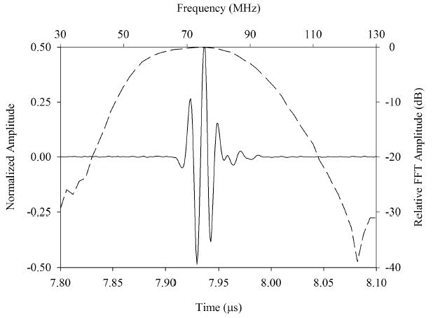
Measured pulse-echo response for the 75 MHz transducer (top) and 35 MHz transducer (bottom). The axes on the bottom and left of each plot refer to the time domain pulse waveforms (solid line). The axes on the top and right refer to the pulse frequency spectrum (dashed line).
Figure 3 is a gray-scale MBF parameter image of the post-LASIK cornea with scanning performed at 35 MHz. At this frequency, the corneal interfaces (anterior and posterior surfaces, Bowman’s membrane, and the LASIK surgical interface) appear as reflective surfaces, with negligible backscatter from the stroma. The LASIK interface is seen faintly, and there are some irregularities in Bowman’s membrane and within the stromal component of the flap. A comparative MBF parameter image obtained from 75 MHz data of the same cornea is shown in figure 4. The flap is seen mainly as a discontinuity in stromal backscatter between the stromal component of the flap and residual stroma. Discontinuities are seen in Bowman’s layer, indicative of microfolds or breaks. Comparative 35 MHz and 75 MHz rf plots obtained from vectors in the central cornea are presented in figure 5. Here, the relatively higher level of backscatter obtained at 75 MHz is evident as is the reduced level of backscatter (2 to 3 dB) in the anterior (flap) versus posterior (residual) stromal components.
FIG. 3.
LASIK-treated cornea six years post-treatment imaged at 35 MHz. The MBF image on the left is in a distorted rectilinear format, with the geometrically corrected image on the right. The flap is seen faintly (wedges). The stroma produces only faint backscatter.
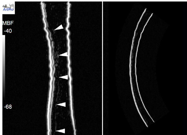
FIG. 4.

Same cornea seen in figure 3 scanned at 75 MHz. Here, the stroma produces significantly higher back-scatter than that seen at 35 MHz. Small arrows indicate various discontinuities in Bowman’s layer, at the interface of the 50 μm thick epithelium and the underlying stroma. The stroma anterior to the ablation interface is approximately 2–3 dB lower in mean backscatter than the posterior residual stroma.
FIG. 5.
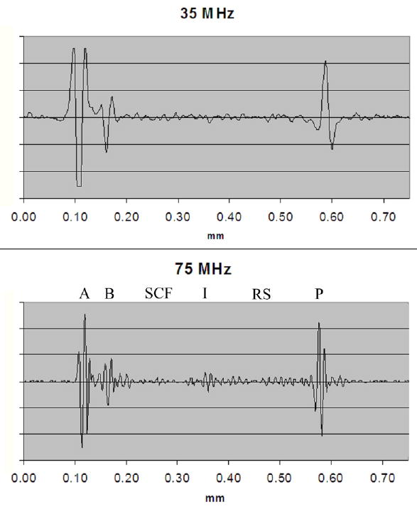
Rf plots of vector through central cornea at 35 MHz and 75 MHz. Various structures are labeled in the 75 MHz plot: A = anterior surface, B = Bowman’s membrane, SCF = stromal component of the flap, I = interface (ablation surface), RS = residual stroma, P = posterior surface. The relatively reduced backscatter in the stromal component of the flap compared to the residual stroma is evident in the 75 MHz image.
Figures 6 and 7 are respectively 35 MHz and 75 MHz MBF images of the nasal quadrant of the anterior segment. The images encompass the peripheral cornea, iris, conjunctiva and sclera as well as part of the lens. The 75 MHz transducer provided sufficient sensitivity to visualize the ciliary body and iris and a small but noticeable improvement in resolution and texture. The layering of the conjunctiva and sclera are better delineated at the higher frequency as well.
FIG. 6.

35 MHz MBF images of a quadrant of LASIK-treated eye showing iris (I), ciliary processes (CP), conjunctiva (C), sclera (S) and lens surface (L). Insertion point of flap (F) is seen in peripheral cornea
FIG. 7.
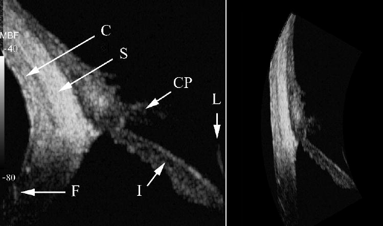
75 MHz MBF images of quadrant of LASIK-treated eye. Iris (I), ciliary processes (CP), conjunctiva (C), sclera (S), lens surface (L) and flap insertion point (F) are indicated.
DISCUSSION
In this report, we described fabrication and clinical application of a 75 MHz, lithium niobate transducer for imaging of the anterior segment of the eye. We demonstrated that this transducer had sufficient sensitivity for visualization of both the cornea and internal ocular structures such as the ciliary body under clinical conditions.
The cornea, made up primarily of collagen in a proteoglycan matrix, is organized as broad 1–2 μm thick belts (lamellae) that run parallel to the corneal surface. The lamellae are themselves composed of collagen fibrils that are about 30 nm in diameter, with center-to-center spacing of about 60 nm.19 The cornea’s transparency is generally considered to be a consequence of destructive interference of light scattered in all but the forward direction by the ordered arrangement of the collagen fiber lattice.20 Any disturbance to this orderly arrangement results in loss of transparency.21 In the post-LASIK cornea examined in this study, we noted that backscatter in the stromal component of the flap was lower than that in the residual stroma. This might relate to biomechanical effects: in LASIK surgery the lamellae of the stromal component of the flap are permanently severed at the edges of the flap.22 Alternatively, this observation might relate to alteration of the hydration gradient known to exist in the cornea, which increases from anterior to posterior.23 Potentially, the interruption of the stroma at the surgical ablation interface might alter this gradient, which in turn affects spacing of lamellae and fibers that might act as backscatter components. While these acoustic scattering changes were observed in this subject, corneal opacification was not present nor did the subject report glare. This might relate to the order-of-magnitude difference in the dimensions of scatterers affecting ultrasound versus light (wavelength <1 μm).
The greater sensitivity to backscatter obtained at 75 MHz might be particularly useful in screening for conditions involving stromal changes such as keratoconnus and kerectasia, which today can only be detected by changes in surface topography, when the disease may be relatively advanced. The demonstrated capacity to visualize the iris and ciliary body may be useful for functional anatomic studies related to accommodation and assessment of the ciliary body’s response to glaucoma medications aimed at reducing aqueous fluid production.
In summary, we have described fabrication and initial clinical use of a 75-MHz, lithium niobate transducer. Its high sensitivity offers the potential for development of clinically practical devices for examination of the cornea, ciliary body and angle structures such as the trabecular meshwork and Schlemn’s canal.
Acknowledgments
Supported by NIH Grants EB000238, P41-EB2182 and Research to Prevent Blindness.
References
- 1.Sherar MD, Foster FS. The design and fabrication of high frequency poly(vinylidene fluoride) transducers. Ultrasonic Imaging. 1989;11:75–94. doi: 10.1177/016173468901100201. [DOI] [PubMed] [Google Scholar]
- 2.Sherar MD, Starkoski BG, Taylor WB, Foster FS. A 100 MHz B-scan ultrasound backscatter microscope. Ultrasonic Imaging. 1989;11:95–105. doi: 10.1177/016173468901100202. [DOI] [PubMed] [Google Scholar]
- 3.Pavlin CJ, Sherar MD, Foster FS. Subsurface ultrasound microscopic imaging of the intact eye. Ophthalmology. 1990;97:244–250. doi: 10.1016/s0161-6420(90)32598-8. [DOI] [PubMed] [Google Scholar]
- 4.Pavlin CJ, Harasiewicz K, Shera MD, Foster FS. Clinical use of ultrasound Biomicroscopy. Ophthalmology. 1991;98:287–295. doi: 10.1016/s0161-6420(91)32298-x. [DOI] [PubMed] [Google Scholar]
- 5.Pavlin CJ, Harasiewicz K, Foster FS. Ultrasound biomicroscopy of anterior segment structures in normal and glaucomatous eyes. Am J Ophthalmol. 1992;113:381–389. doi: 10.1016/s0002-9394(14)76159-8. [DOI] [PubMed] [Google Scholar]
- 6.Reinstein DZ, Silverman RH, Coleman DJ. High-frequency ultrasound measurement of the thickness of the corneal epithelium. Refract Corn Surg. 1993;9:385–387. [PubMed] [Google Scholar]
- 7.Reinstein DZ, Silverman RH, Rondeau MJ, Coleman DJ. Epithelial and corneal thickness measurements by high-frequency ultrasound digital signal processing. Ophthalmology. 1994;101:140–146. doi: 10.1016/s0161-6420(94)31373-x. [DOI] [PubMed] [Google Scholar]
- 8.Reinstein DZ, Silverman RH, Trokel SL, Coleman DJ. Corneal pachymetric topography. Ophthalmology. 1994;101:432–438. doi: 10.1016/s0161-6420(94)31314-5. [DOI] [PubMed] [Google Scholar]
- 9.Ye SG, Harasiewicz KA, Pavlin CJ, Foster FS. Ultrasound characterization of normal ocular tissue in the frequency range from 50 MHz to 100 MHz. IEEE Trans Ultrason Ferroelectr Freq Contr. 1995;42:8–14. [Google Scholar]
- 10.Snook KA, Zhao J-Z, Alves CH, et al. Design, fabrication, and evaluation of high frequency, single-element transducers incorporating different materials. IEEE Trans Ultrason Ferroelectr Freq Contr. 2002;49:169–176. doi: 10.1109/58.985701. [DOI] [PubMed] [Google Scholar]
- 11.Zipparo MJ, Shung KK, Shrout TR. Piezoceramics for high-frequency (20–100 MHZ) single-element imaging transducers. IEEE Trans Ultrason Ferroelectr Freq Contr. 1997;44:1038–1048. [Google Scholar]
- 12.Feng G-H, Sharp CC, Zhou QF, et al. Fabrication of MFMS ZnO dome-shaped-diaphragm transducers for high-frequency ultrasonic imaging. J Micromec Microeng. 2005;15:586–590. [Google Scholar]
- 13.Yokosawa K, Shinomura R, Sano S, et al. A 120-MHz ultrasound probe for tissue imaging. Ultrasonic Imaging. 1996;18:231–239. doi: 10.1177/016173469601800401. [DOI] [PubMed] [Google Scholar]
- 14.Cannata JM, Ritter T, Silverman R, Shung K. Design of efficient, broadband single element (20–80 MHz) ultrasonic transducers for medical imaging applications. IEEE Trans Ultrason Ferroelectr Freq Contr. 2003;50:1548–1557. doi: 10.1109/tuffc.2003.1251138. [DOI] [PubMed] [Google Scholar]
- 15.Foster FS, Pavlin CJ, Harasiewicz KA, Christopher DA, Turnbull DH. Advances in ultrasound microscopy. Ultrasound Med Biol. 2000;26:1–27. doi: 10.1016/s0301-5629(99)00096-4. [DOI] [PubMed] [Google Scholar]
- 16.Knapik DA, Starkoski B, Palvin CJ, Foster FS. A 100–200 MHz ultrasound biomicroscope. IEEE Trans Ultrason Ferroelectr Freq Contr. 2000;47:1540–1549. doi: 10.1109/58.883543. [DOI] [PubMed] [Google Scholar]
- 17.Lizzi FL, Astor M, Feleppa EJ, Shao M, Kalisz A. Statistical framework for ultrasonic spectral parameter imaging. Ultrasound Med Biol. 1997;23:1371–82. doi: 10.1016/s0301-5629(97)00200-7. [DOI] [PubMed] [Google Scholar]
- 18.Robert M, Molingou G, Snook K, Cannata J, Shung KK. Fabrication of focused poly(vinylidene fluoride-trifluoroethylene) P(VDF-TrFE) copolymer 40–50 MHz ultrasonic transducers on curved surfaces. J Appl Phys. 2004;96:252–256. [Google Scholar]
- 19.Meek KM, Boote C. The organization of collagen in the corneal stroma. Exp Eye Res. 2004;78:503–512. doi: 10.1016/j.exer.2003.07.003. [DOI] [PubMed] [Google Scholar]
- 20.Maurice DM. The structure and transparency of the cornea. J Physiol. 1957;136:263–286. doi: 10.1113/jphysiol.1957.sp005758. [DOI] [PMC free article] [PubMed] [Google Scholar]
- 21.Griffiths SN, Drasdo N, Barnes DA, Sabell AG. Effect of epithelial and stromal edema on the light scattering properties of the cornea. Am J Optom Physiol Opt. 1986;63:888–894. doi: 10.1097/00006324-198611000-00005. [DOI] [PubMed] [Google Scholar]
- 22.Roberts C. The cornea is not a piece of plastic. J Refract Surg. 2000;16:407–413. doi: 10.3928/1081-597X-20000701-03. [DOI] [PubMed] [Google Scholar]
- 23.Komai Y, Ushiki T. The three dimensional organization of collagen fibrils in the human cornea and sclera. Invest Ophthalmol Vis Sci. 1991;32:2244–2258. [PubMed] [Google Scholar]