

Abstract
Plugging a gap in screening
Arrays of nanoliter-sized plugs of different compositions can be preformed in a three-phase liquid/liquid/gas flow. The arrays can be transported into a microfluidic channel to test against a target (see schematic representation), as demonstrated in protein crystallization and an enzymatic assay.
Keywords: crystal growth, enzymatic arrays, microreactors, screening methods, three-phase system
Herein, we describe a simple, economical microfluidic method of screening a small volume (down to submicroliter volumes) of a solution against a large number of reagents on the nanoliter scale. The use of microfluidics to miniaturize chemical and biological screening is an important and active area of research in such diverse areas as biochemical assays, protein crystallization, and combinatorial chemistry.[1–7] Nanoliter aqueous plugs (droplets) transported through microchannels in an immiscible liquid have been used in a liquid/liquid flow system and allow miniaturization while eliminating dispersion,[8,9] accelerating mixing,[10] and providing control over the surface chemistry.[11] Applications of such systems to protein crystallization,[3,12] kinetic measurements,[10] assays,[13,14] DNA analysis,[8] and chemical synthesis[15] have been demonstrated.
Such plug-based microfluidic systems have been especially attractive for applications in which the concentrations of several reagents had to be varied. The concentrations were varied by rapidly changing the flow rates of the reagent streams as the droplets were formed.[3,12] Plug-based methods of that type require equipment for varying flow rates, and even though such equipment could be as simple as a few computer-controlled syringe pumps, this requirement presents a barrier to many potential users in chemical and biochemical laboratories. In addition, to increase the number of reagents that can be screened, both the number of the microfluidic channels in the device and the number of flow control devices have to be increased proportionally. Herein, we implement a complementary approach that uses pre-formed arrays of plugs to simplify the experiment for the user, relies on a liquid/liquid/gas three-phase flow system to ensure robustness, and allows a much larger number of reagents to be tested in a scalable fashion.
This approach consists of two steps. In the first step, an array of nanoliter plugs of many different reagents, separated and surrounded by a fluorinated carrier fluid, was generated inside a hydrophobic glass or plastic capillary (Figure 1a). The reagents in plugs may be stored inside sealed capillaries for months without evaporation or exposure to the ambient environment.[12] Such a two-phase system works well for fluids of matched viscosities. However, plugs may coalesce during subsequent use if the viscosity of the carrier fluid is very different from that of the aqueous solutions inside the plugs or if the viscosities within different plugs vary significantly. We used a three-phase liquid/liquid/gas system to enhance reliability in the manipulation and transport of these plugs: we separated the plugs by gas bubbles (Figure 1b,c) in addition to the carrier fluid. Formation of air bubbles in microfluidic devices has been previously described,[16] and gas bubbles have been used to separate liquid slugs of reagents in a liquid/gas two-phase flow, with applications for the synthesis of nanoparticles in microfluidic devices,[17,18] and have been used for actuation of steady microfluidic flow.[19] In addition, air bubbles have been widely used in biochemical analyzers.[20]
Figure 1.
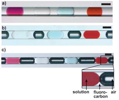
a) An array of plugs of four different reagents in a capillary. The plugs contain KMnO4 (purple), NaCl (colorless), CuSO4 (blue), and Fe(SCN)3 (red), respectively. The colorless fluid is fluorocarbon. b,c) An array of plugs of different reagents formed in fluorocarbon and separated by air bubbles (dark) in a capillary. In (b) the aqueous plugs are separated from the air bubbles by a layer of fluorocarbon, thereby preventing cross-communication between the plugs. The scale bars are 200 μm.
Herein, we use a liquid/liquid/gas three-phase flow system, in which the aqueous phase remains surrounded by the fluorocarbon, because the surface tension of the water–air interface (≈70 mNm−1) is significantly higher than both the surface tension of the water–fluorocarbon interface (≈15 mNm−1 with fluorosurfactants)[11] and the surface tension of the air–fluorocarbon interface. When there was only a wetting film of fluorocarbon between the air bubble and the aqueous plug (Figure 1c), and the osmotic pressures of the adjacent plugs were different, water transport between plugs was observed. Such water transport was prevented for several months when more fluorocarbon was used to separate the air bubbles and the plugs (Figure 1b).
In the second step, to perform the screening, the array was flowed from the capillary, through a funnel-shaped adapter (Figure 2a), into a microfluidic channel with a simple T-junction. The funnel-shaped adapter was used to couple the capillary with the microchannel. As the capillary was inserted into the adapter, a leak-proof connection was established without using any sealant. The microfluidic device could therefore be reused with experiments set up in multiple capillaries, one after another. As the array of plugs flowed into the microchannel, an aqueous target stream was allowed to flow into the side channel of the T-junction. The plugs merged with the stream[15] to give larger plugs (Figure 2b), each containing one reagent from the array and the target sample. This merging has previously been characterized in detail.[15] Because of the surface tension at the gas/liquid interface and the elasticity of polydimethylsiloxane, the aqueous stream was not injected into small air bubbles, such as those shown in Figure 1b. The solutions were mixed in a volume ratio of 1:1, which was determined by the ratio of the two volumetric flow rates. A winding channel could be incorporated with the T-junction to accelerate mixing after merging, as demonstrated in nanoparticle synthesis in plugs in microchannels.[15] After merging, the plugs flowed into another capillary where they could be stored and monitored.
Figure 2.
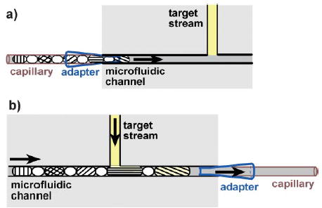
A schematic illustration of the process of utilizing an array of plugs for screening. a) The capillary containing the array of plugs is inserted into an adapter that is coupled with the inlet of the microfluidic channel. The array of plugs is then transported into the channel. b) As the array of plugs flows through the channel, each plug merges with a stream of the target solution, and the resulting plugs are collected in another capillary.
We illustrated this technique by performing a functional assay in which a set of enzymes was screened for phosphatase activity, by using a fluorogenic substrate, fluorescein diphosphate (FDP). Such an assay would be important for identifying a protein with the desired functional activity among thousands of proteins produced by the proteomics efforts. An array of plugs (≈15 nL) of alkaline phosphatase (AP), catalase, ribonuclease A (RNase), and lysozyme was first prepared in a capillary (Figure 3, see the Supporting Information for details). To eliminate potential false positives that result from the contamination of the substrate stream with an active enzyme, we separated every two neighboring enzyme plugs with two blank plugs containing phosphate-buffered saline (PBS; pH 7.4). Air bubbles were inserted between every two neighboring plugs. To assay the activity of the four enzymes on the FDP substrate, the array of plugs was merged with the solution of FDP at a T-junction (Figure 3a). The hydrolysis of FDP, which is catalyzed by AP, released fluorescein and was detected by fluorescence microcopy (Figure 3b). The plugs of the other three enzymes did not show any fluorescence, thereby confirming the lack of reactivity and the absence of contamination.
Figure 3.
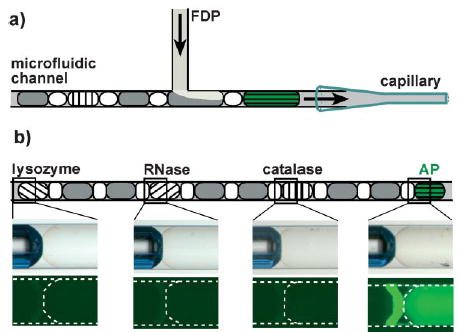
a) A schematic illustration of the assay of multiple enzymes against a single substrate (FDP). b) The result of the enzymatic assay. The drawing at the top illustrates the array of plugs. The plugs of PBS are in gray, the air bubbles are in white, and the plugs of enzymes are hatched. The microscope images in the middle are the bright-field micrographs of the plugs after merging. The images at the bottom are fluorescence micrographs of the corresponding plugs. In the rightmost fluorescence micrograph, the bright line is because of the reflection of the fluorescence of the AP plug from the edge of the air bubble. The dashed line indicates the outline of the capillary and the plugs.
Next, we demonstrated screening of a single protein against multiple crystallizing agents. We preformed plugs (≈15 nL) of 48 precipitants (numbered 1–48) from the crystal screen kit (Hampton Research) in a capillary. These plugs were merged with a stream of thaumatin, thereby giving rise to 48 crystallization trials. A total volume of less than 1.0 μL of thaumatin solution (60 mgmL−1 in 0.1mN-(2-acetamido)-iminodiacetic acid buffer, pH 6.5) was used to fill the inlet tubing and the inlet of the microchannel, by using a syringe and tubing prefilled with carrier fluid to minimize waste of the protein solution. During the screening process, a volume of about 0.9 μL of thaumatin solution was consumed for screening and less than 0.1 μL remained in the channel. The merged plugs were transferred into the receiving capillary. Solutions of very different viscosities (from 1.0–33 cP)[21] were handled reliably in this system. Precipitation occurred during the merging of thaumatin with the plugs containing precipitant 30 (0.2m(NH4)2SO4/30% poly(ethylene glycol)8000). However, it did not interfere with the experiment because plugs are capable of transporting solids without allowing them to contact the walls of the microchannel.[15] After incubation for 36 h, we observed formation of crystals in plugs with precipitant 29 (0.8m potassium sodium tartrate/0.1m 2-[4-(2-hydroxyethyl)-1-piperazinyl]ethanesulfonic acid, pH 7.5) and no crystals in any other plugs, in agreement with experiments performed with microliter droplets. The screening results for three of the precipitants from the crystal screen kit are shown in Figure 4 (see the Supporting Information for experimental details).
Figure 4.
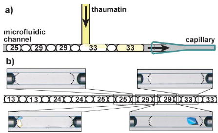
a) A schematic illustration of the screening of multiple precipitants for protein crystallization. b) The result of the precipitant screening. The drawing (middle) shows the merged plugs containing the precipitant and thaumatin, separated by the air bubbles. The numbers are the index numbers of the precipitants from the crystal screen kit. The four polarized-light micrographs show plugs that contain a mixture of thaumatin and precipitants 25, 29 (× 2), and 33, respectively. Only the plugs containing precipitant 29 yielded crystals. The refractive index match between the fluorocarbon and the aqueous phases enables the observation of crystals at the edges of plugs, because the boundaries of the plugs are barely visible (shown with dashed lines).
The approach described here is capable of screening microliter and submicroliter total volumes against multiple nanoliter volumes of reagents. We have demonstrated both screening of multiple proteins against a single reagent and screening of a single protein against many reagents. In the area of protein crystallization, this method enables sparse-matrix screening and is complementary to the methods for optimization of concentration that we developed previously.[3,12] It should be possible to use alternating plugs[12] to extend this method from the microbatch technique shown here to the vapor-diffusion technique.
This method has the following attractive features: 1) It is scalable—an increase in the number of reagents used in a screen does not require more complex fabrication, just a longer receiving capillary. 2) It is made reliable by the use of three-phase flow, in which a fluorinated carrier fluid provides protection of the plugs and control of surface chemistry, while gas bubbles prevent aqueous plugs from merging. 3) Arrays may be prefabricated by a range of methods, from simple methods with syringes to robotics.[22–24] Prefabricated arrays of plugs sealed in capillaries may be stored for months and could be made sterile or prepared under inert atmosphere, thereby expanding the range of potential applications. 4) The method is very simple for the end user—no sophisticated equipment is required at the user3s end except a source of constant flow to drive the two streams to merge. A potential disadvantage of this method for some applications is that it is serial, rather than a parallel approach with multiple reagents against multiple substrates,[2,25] although some simple methods are quite effective even in serial format.[26] Overall, this method is attractive for applications in which reagents must be stored and used in a simple, reliable format, such as in diagnostics and detection. In addition, this method may find a wide range of applications in chemistry and biochemistry, by enhancing and miniaturizing current methods in which reagents are stored or distributed in 96- and 384-well plates, such as those in the fields of combinatorial chemistry, protein crystallization, and biochemical assaying.
A very interesting paper just appeared[27] that describes the use of preformed plugs in a cartridge for immunoassays. Microliter plugs were prepared in tubes by using a two-phase liquid/gas system, in which aqueous droplets were separated by air. By passing the droplets over surfaces loaded with antigens, immunoassays were conducted. The three-phase system described herein is different because, at least in our hands, it enables reliable transport of nanoliter volumes of aqueous solutions, prevents contact of aqueous solutions with the walls and eliminates dispersion, and prevents diffusion of water vapor from one aqueous plug to another. These differences are not essential for applications such as immunoassays—in fact the three-phase system may be less suitable for immunoassays or other reactions performed on the solid surface of a chip—but they are important in nanoliter enzymatic assays and protein crystallization. The two-phase system[27] is simpler to operate, because the flow rates do not need to be controlled at all, so the experiment may be performed even in the absence of electricity. This simplicity will be especially important for analysis in resource-poor settings.[27] Overall, the two approaches appear to be complementary in both their execution and their range of applications.
Supplementary Material
Footnotes
This work was supported by the National Institutes of Health (grant no. R01EB001903) and by the Beckman Young Investigator Program and was performed at the MRSEC microfluidic facility funded by the National Science Foundation. We thank David Adamson for invaluable experimental assistance.
References
- 1.Hansen CL, Skordalakes E, Berger JM, Quake SR. Proc Natl Acad Sci USA. 2002;99:16531. doi: 10.1073/pnas.262485199. [DOI] [PMC free article] [PubMed] [Google Scholar]
- 2.Liu J, Hansen C, Quake SR. Anal Chem. 2003;75:4718. doi: 10.1021/ac0346407. [DOI] [PubMed] [Google Scholar]
- 3.Zheng B, Roach LS, Ismagilov RF. J Am Chem Soc. 2003;125:11170. doi: 10.1021/ja037166v. [DOI] [PubMed] [Google Scholar]
- 4.Watts P, Haswell SJ. Curr Opin Chem Biol. 2003;7:380. doi: 10.1016/s1367-5931(03)00050-4. [DOI] [PubMed] [Google Scholar]
- 5.Kobayashi J, Mori Y, Okamoto K, Akiyama R, Ueno M, Kitamori T, Kobayashi S. Science. 2004;304:1305. doi: 10.1126/science.1096956. [DOI] [PubMed] [Google Scholar]
- 6.Nagaki A, Kawamura K, Suga S, Ando T, Sawamoto M, Yoshida J. J Am Chem Soc. 2004;126:14702. doi: 10.1021/ja044879k. [DOI] [PubMed] [Google Scholar]
- 7.Suga S, Nagaki A, Yoshida J. Chem Commun. 2003:354. doi: 10.1039/b211433j. [DOI] [PubMed] [Google Scholar]
- 8.Burns MA, Johnson BN, Brahmasandra SN, Handique K, Webster JR, Krishnan M, Sammarco TS, Man PM, Jones D, Heldsinger D, Mastrangelo CH, Burke DT. Science. 1998;282:484. doi: 10.1126/science.282.5388.484. [DOI] [PubMed] [Google Scholar]
- 9.Velev OD, Prevo BG, Bhatt KH. Nature. 2003;426:515. doi: 10.1038/426515a. [DOI] [PubMed] [Google Scholar]
- 10.Song H, Tice JD, Ismagilov RF. Angew Chem. 2003;115:792. doi: 10.1002/anie.200390203. Angew. Chem. Int. Ed. 2003, 42, 768. [DOI] [PubMed] [Google Scholar]
- 11.Roach LS, Song H, Ismagilov RF. Anal Chem. 2005;77:785. doi: 10.1021/ac049061w. [DOI] [PMC free article] [PubMed] [Google Scholar]
- 12.Zheng B, Tice JD, Roach LS, Ismagilov RF. Angew Chem. 2004;116:2562. doi: 10.1002/anie.200453974. Angew. Chem. Int. Ed. 2004, 43, 2508. [DOI] [PMC free article] [PubMed] [Google Scholar]
- 13.Zheng B, Tice JD, Ismagilov RF. Anal Chem. 2004;76:4977. doi: 10.1021/ac0495743. [DOI] [PMC free article] [PubMed] [Google Scholar]
- 14.Srinivasan V, Pamula VK, Fair RB. Anal Chim Acta. 2004;507:145. [Google Scholar]
- 15.Shestopalov I, Tice JD, Ismagilov RF. Lab Chip. 2004;4:316. doi: 10.1039/b403378g. [DOI] [PubMed] [Google Scholar]
- 16.Garstecki P, Gitlin I, DiLuzio W, Whitesides GM, Kumacheva E, Stone HA. Appl Phys Lett. 2004;85:2649. [Google Scholar]
- 17.Khan SA, Gunther A, Schmidt MA, Jensen KF. Langmuir. 2004;20:8604. doi: 10.1021/la0499012. [DOI] [PubMed] [Google Scholar]
- 18.Gunther A, Khan SA, Thalmann M, Trachsel F, Jensen KF. Lab Chip. 2004;4:278. doi: 10.1039/b403982c. [DOI] [PubMed] [Google Scholar]
- 19.Marmottant P, Hilgenfeldt S. Proc Natl Acad Sci USA. 2004;101:9523. doi: 10.1073/pnas.0307007101. [DOI] [PMC free article] [PubMed] [Google Scholar]
- 20.Small H, Langhorst MA. Anal Chem. 1982;54:A892. [Google Scholar]
- 21.Ninni L, Burd H, Fung WH, Meirelles AJA. J Chem Eng Data. 2003;48:324. [Google Scholar]
- 22.Kuhn P, Wilson K, Patch MG, Stevens RC. Curr Opin Chem Biol. 2002;6:704. doi: 10.1016/s1367-5931(02)00361-7. [DOI] [PubMed] [Google Scholar]
- 23.Hui R, Edwards A. J Struct Biol. 2003;142:154. doi: 10.1016/s1047-8477(03)00046-7. [DOI] [PubMed] [Google Scholar]
- 24.Meldrum DR, Evensen HT, Pence WH, Moody SE, Cunningham DL, Wiktor PJ. IEEE-ASME Trans Mechatron. 2000;5:212. [PMC free article] [PubMed] [Google Scholar]
- 25.Ismagilov RF, Ng JMK, Kenis PJA, Whitesides GM. Anal Chem. 2001;73:5207. doi: 10.1021/ac010502a. [DOI] [PubMed] [Google Scholar]
- 26.Suga S, Okajima M, Fujiwara K, Yoshida J. J Am Chem Soc. 2001;123:7941. doi: 10.1021/ja015823i. [DOI] [PubMed] [Google Scholar]
- 27.Linder V, Sla SK, Whitesides GM. Anal Chem. 2004;76:64. doi: 10.1021/ac049071x. [DOI] [PubMed] [Google Scholar]
Associated Data
This section collects any data citations, data availability statements, or supplementary materials included in this article.