

Abstract
Fundamental and applied research in chemistry and biology benefits from opportunities provided by droplet-based microfluidic systems. These systems enable the miniaturization of reactions by compartmentalizing reactions in droplets of femoliter to microliter volumes. Compartmentalization in droplets provides rapid mixing of reagents, control of the timing of reactions on timescales from milliseconds to months, control of interfacial properties, and the ability to synthesize and transport solid reagents and products. Droplet-based microfluidics can help to enhance and accelerate chemical and biochemical screening, protein crystallization, enzymatic kinetics, and assays. Moreover, the control provided by droplets in microfluidic devices can lead to new scientific methods and insights.
Keywords: analytical systems, interfaces, microfluidics, microreactors, plugs
1. Introduction: Reactions in Droplets
This Review discusses the use of droplets in microfluidic channels as chemical microreactors for performing many reactions on a small scale (Figure 1).[1] Microreactors in general[2] and bulk micellar systems[3] have been covered in recent review articles in Angewandte Chemie and thus will not be covered herein. We describe new techniques that have been developed to perform chemical reactions within droplets and reactions that have been studied by using droplets. We also discuss how droplet-based microfluidics can lead to new scientific methods and insights.
Figure 1.
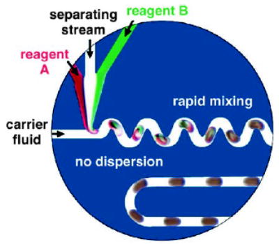
Droplets formed within microfluidic channels can serve as microreactors. In this example, the reactions are performed within aqueous droplets, which contain reagent A, reagent B, and a separating stream containing buffer. The droplets are encapsulated by a layer of a fluorinated carrier fluid and transported through the microchannels. Reprinted from reference [1].
1.1. Reaction Control for High Throughput
A number of applications require multiple reactions to be performed in parallel, for example, drug discovery, gene-expression analysis, and high-throughput assays. For these applications, it is only feasible to perform reactions on a microscale, because reagents can be expensive or only available in limited amounts. In other applications, multiple reactions need to be carried out to characterize stochastic processes, such as the nucleation of crystals.
Microfluidics can be used to handle small volumes of liquid and is a promising method to form microreactors.[2,4,5] Benefits from miniaturization include low consumption of reagents and high-throughput fabrication of devices. For example, soft lithography with poly(dimethylsiloxane) (PDMS) can be used for the rapid and inexpensive fabrication[6,7] and modification[8–10] of devices.
1.2. Parallel or Serial Compartmentalization of Multiple Reactions
To perform many reactions in high throughput, each reaction condition must be uniquely addressable or indexed. The reactions can be indexed if each reaction condition is compartmentalized either in parallel or in series[11] (Figure 2). Reaction conditions can be compartmentalized in parallel by using a well plate (Figure 2a). The final result of the reaction is indexed as a function of the spatial location of the well.[12–14] Reaction conditions can also be compartmentalized in series as in flow injection analysis (Figure 2b). The final result of the reaction is indexed as a function of the elution time. Chemical indexing in combinatorial chemistry has also been achieved by using molecular tags,[15] labeled beads,[16,17] and encoded particles.[18,19]
Figure 2.
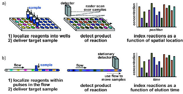
Comparison of reactions compartmentalized in parallel and in series. a) Parallel reactions performed by using well plates: The reagents are localized within wells, and the target sample is delivered to the well through a multipipettor. The reaction products are detected by scanning over the samples, and each reaction is indexed as a function of the spatial location of each well. b) Serial reactions performed by using flow. Reactions are localized within pulses and separated by a buffer solution between each reagent. These pulses are transported through the reaction tube by the flow, and the target sample is delivered to the reagents. The pulses are transported by the flow past a stationary detector to analyze the reaction products. Each reaction is indexed as a function of the elution time.
1.3. Control of the Compartmentalization
For performing reactions in parallel, the handling of the fluid and evaporation within the compartments needs to be controlled. PDMS devices with enclosed chambers and valves allow many reactions to be performed by multiplexing methods.[20–23] This system has been applied to protein crystallization,[24–26] bacterial chemostats,[27] and the synthesis of radiolabeled probes.[22] The valves used to handle fluids require multilayer fabrication. As PDMS is permeable to the vapor of organic and aqueous solutions, eliminating evaporation through PDMS requires special measures (although this permeability was controlled and used as an advantage in some applications,[28] such as the filling of dead-end channels).[25]
For reactions performed in series in a single-phase flow, dispersion can lead to cross-contamination of reaction conditions and dilution of samples. Pressure-driven flow of a single-phase solution through a microchannel is laminar and displays a parabolic velocity profile.[29,30] As a result of the parabolic flow profile, the reagents in solution are transported at a range of velocities in the microchannel. Taylor dispersion describes the transport and broadening of a pulse of a solute within a solution that is flowing through a tube.[29,30] As a result of dispersion, localization of the reaction and accurate control of the reaction time is difficult. Cross-contamination can occur between pulses of different reagents that are traveling through the same tube. Furthermore, reagents are in direct contact with the solid microchannel wall, so the surface chemistry of the wall must be controlled. The control of surface chemistry is especially critical for devices that use electroosmotic flow to solve the problem of Taylor dispersion.[31,32] Dilution of the sample solution can occur through diffusion within a single-phase flow, especially with prolonged incubation times. This broadening of the sample pulse occurs regardless of whether the flow is driven by pressure or electroosmotic forces.
1.4. Compartmentalization in Nanoliter-Sized Droplets
Nanoliter-sized droplets can serve as compartments for reactions. Multiple reactions can be performed by varying the reaction conditions within each droplet. The problems of evaporation, complicated fluid handling, dispersion, and diffusion can be overcome by using multiphase flows of immiscible liquids to form droplets in microfluidic channels (Figure 1).[1] Evaporation can be controlled for long-term incubation experiments by transporting droplets into glass capillaries.[33,34] Complicated fluid handling is minimized, as uniformly sized droplets form spontaneously in a cross-stream flow of two immiscible liquids.[1,35–39] The flow of fluids within the microchannels can be used to manipulate droplets and arrays of droplets in a controlled manner.[1,37,38,40–42] Dispersion due to convection and diffusion is eliminated because the reagents are encapsulated within droplets. Furthermore, surface chemistry can be easily controlled at the liquid–liquid interface between the immiscible phases of the reagent fluid and the carrier fluid.[43] Mixing within droplets can be achieved by chaotic advection.[1,37,40,44,45]
To obtain compartments that do not move (as analogues of well plates), droplets can be transported into capillaries and incubated for up to one year. To obtain compartments that move (as analogues of flow injection analysis), flow can be used to transport droplets continuously through the microchannel in the device. By using droplets, it is possible both to compartmentalize reactions and control the reaction time accurately.
1.5. Scope of the Review
In this Review, we discuss reactions that occur within segmented flows in a microfluidic system. Segmented flows are composed of at least two immiscible phases: one dispersed phase and one continuous phase. The droplet consists of the dispersed phase, and the continuous phase encapsulates the droplet and preferentially wets or coats the surface of the microchannel.
For this Review, we differentiate between two types of segmented flows on the basis of the phase in which the reaction takes place. In the first type, discrete liquid droplets are encapsulated by a carrier fluid that wets the microchannel (Figure 3a).[1] These droplets, termed “plugs” herein, form the dispersed phase in which the reactions occur. Systems that use plugs differ from segmented-flow injection analysis in that reagents in plugs do not come into contact with the microchannel wall and are transported without dispersion. In the second type of segmented flow, liquid “slugs” are separated by discrete gas bubbles (Figure 3b).[46–51] In this case, reactions occur within the slugs that form the continuous phase; reagents are exposed to the walls of the channels and some dispersion occurs. This second system is similar to segmented-flow injection analysis.[52–56] For the remainder of the Review, the terms “plugs” and “slugs” are used to differentiate these two types of segmented flows.
Figure 3.
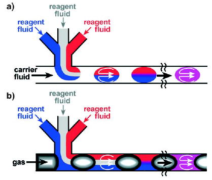
Reactions can be studied in two types of segmented flows in microfluidic channels. a) Discrete liquid plugs are encapsulated by an immiscible continuous phase (for example, a fluorocarbon-based carrier fluid). Reactions occur within the dispersed phase (within the plugs). Owing to the surface properties of the microchannel walls, these walls are preferentially wet by the continuous phase. b) Aqueous slugs are separated by another immiscible phase (for example, discrete gas bubbles). Reactions occur within the continuous phase (i.e., within the slugs).
We do not cover reactions in bulk systems that use multiple immiscible phases to form micelles, emulsions, and droplets. Emulsions take advantage of only some of the spatial control available by compartmentalization. Extensive review articles cover reactions in micelles,[3] colloids,[57,58] miniemulsions,[59] and multilayer microcapsules.[60] Emulsions and vesicles have been used for in vitro compartmentalization,[61,62] and vesicle reactors can also act as synthetic cells.[63–65] Emulsions formed by microfluidics[66–68] have been used to synthesize permeable colloids[69] and to fabricate monodisperse capsules by using steady coaxial jets.[70]
The area of “digital microfluidics”, in which droplets are manipulated by an array of electrodes[71–75] (“active control”) rather than through a continuous flow (“passive control”), is also not covered. The principles of electrowetting-based actuation and the automation of this technique have been reviewed.[76–78] Digital microfluidic devices have been used for analyzing proteins and peptides with matrix-assisted laser desorption/ionization mass-spectrometry (MALDI MS),[79,80] performing PCR with optical detection,[81] measuring glucose concentration in droplets with optical detection,[82] performing a luciferase-based assay,[83] and synthesizing anisotropic particles.[84]
Microfluidic systems that use multiphase flow but do not report reactions will not be discussed in detail. We define reactions broadly and include the interconversion of chemical species[85] and phase transitions, such as crystallization and the formation of particles. Methods of forming and manipulating droplets are being continuously developed to take advantage of novel physical principles, such as electrowetting,[86–88] magnetic fields,[89,90] optically induced Marangoni effects,[91,92] acoustic waves,[93] and surface chemistry.[94,95] Recent innovations on the generation of gas bubbles in microfluidic devices include the use of segmented flow in microchannels as multiphase monolith reactors,[96] the formation of monodisperse gas bubbles by flow focusing,[97,98] the study of nonlinear dynamics of a flow-focusing bubble generator,[99] and characterization of the transport of bubbles in square channels.[100]
The flow of immiscible fluids within microchannels may result in continuous laminar flow rather than the formation of droplets.[101] These continuous-laminar-flow systems, though suitable for conducting chemical reactions and bioassays,[102–104] as well as for patterning and microfabrication within microchannels,[105,106] are not discussed herein.
This Review summarizes recent developments in the use of droplets in microfluidics as chemical reactors for many reactions. We introduce techniques for conducting reactions and discuss examples of reactions in droplet-based microfluidic systems. Furthermore, we examine how microfluidics can open up new research areas.
2. Criteria for Performing Reactions in Droplets
To perform reactions within microfluidic devices, at least two criteria should be met. First, the microfluidic tool should be able to perform typical procedures that are conducted for reactions on the macroscale. These procedures include the controlled addition of reagents to a reaction mixture, the thorough mixing of reagents, control of the reaction time, the combining and splitting of reaction mixtures for multiple-step reactions, and analysis over the course of a reaction. Second, the microfluidic tool should provide a characteristic advantage, for example, the ability to perform more reactions under more reaction conditions. As with any high-throughput screening technique, there must be a method for organizing and indexing each reaction condition. Likewise, there must be an efficient method for assaying many different conditions and also for optimizing a particular condition. These methods should be scalable, straightforward, and simple. In this section, we discuss techniques that were developed for droplet-based microfluidics to fulfill the two criteria described above.
2.1. Formation of Droplets within Microfluidic Channels
Droplet formation in two-phase systems has been extensively studied for both liquid–liquid flows[107–109] and gas–liquid flows.[110] Although many methods are available for making bulk emulsions, droplets in microfluidic channels have been generated mostly by two techniques: T junctions[1,35–39] and flow-focusing.[36,97,98,111–115] In T junctions, the disperse phase and the continuous phase are injected from two branches of the “T”. Droplets of the disperse phase are produced as a result of the shear force and interfacial tension at the fluid–fluid interface (Figure 4; see also Figure 1). The phase that has lower interfacial tension with the channel wall is the continuous phase.[37] To generate droplets in a flow-focusing configuration, the continuous phase is injected through two outside channels and the disperse phase is injected through a central channel into a narrow orifice (Figure 5).[111] This geometry is only slightly more difficult to implement than a T junction and may facilitate the formation of droplets, especially small or viscous droplets.[45,97,111,115–117] For both methods, surfactants are often added to the continuous phase to stabilize the fluid–fluid interfaces of the droplets.[1,35,111] The conditions under which monodisperse droplets form have been well documented.[96,118–123] The droplets are not useful as general microreactors, however, unless methods of introducing reagents into the droplets are also developed, as is discussed below.
Figure 4.
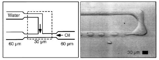
Formation of droplets within a T junction of a microfluidic device.[35] In this case, the oil is a mixture of hydrocarbon and the surfactant Span80, and the channels are made of polymerized acrylated urethane. Reprinted with permission from reference [35]. Copyright 2001 American Physical Society.
Figure 5.
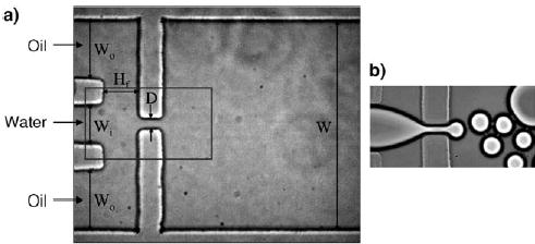
Formation of droplets by flow-focusing.[111] Modified from reference [111]. a) A schematic of the device. The rectangle outlines the field of view in (b). Copyright 2003 American Institute of Physics.
2.2. Introduction of Reagents into Droplets
Different techniques have been developed to introduce reagents into droplets for different droplet-based microfluidic applications. For high-throughput screenings, one target sample must be tested against a large number of different reaction conditions. Each reaction condition may be composed of different reagents or a different combination of a set of reagents. For measuring kinetics or optimizing reaction conditions, only a few reagents need to be incorporated within the droplet, but the concentration of these reagents are varied. For multiple-step reactions, the addition of a reagent should occur at a specific time during the course of the reaction. Each of these applications requires a different method for introducing the reagents.
2.2.1. Cartridge Technique
For screening a large number of reaction conditions against one target sample, preformed cartridges can be produced to store an array of plugs (Figure 6a,b).[42] Each plug contains a different reaction condition of different reagents. For example, an array of 48 plugs was formed in which each plug contained 15 nL of a different reagent.[42] The target sample can be introduced into the preformed plugs by using a microchannel T junction (Figure 6c). Reagent cartridges can be stored inside sealed capillaries for months without evaporation or exposure to the ambient environment.[42]
Figure 6.
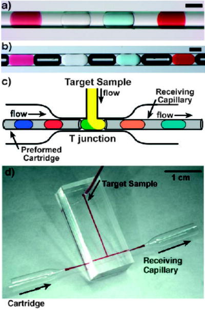
Preformed cartridges of plugs enable the combination of a large number of reagents with a sample in sub-microliter volumes.[42, 124] a,b) Four different reagents stored as an array of plugs in a capillary. The plugs are separated by a fluorocarbon carrier fluid, as well as air bubbles (in b), to prevent cross-communication between the plugs. Scale bars: 200 μm. c) Merging of plugs from a preformed cartridge with a target sample stream through a T junction. The resulting array of plugs is transferred into a receiving capillary and the trials are collected. d) Photograph of the T junction. Reprinted from reference[42] (a,b) and with permission from Elsevier from reference [124] (c,d).
Reagent cartridges can be used for applications that require parallel screening of one target sample against many different reagents or reaction conditions. By using a repeated splitting device, 16 reagent cartridges (each containing approximately 20-nL plugs) were formed in parallel by splitting one array containing large droplets (ca. 320 nL).[125] Such parallel preparation of reagent cartridges accelerates high-throughput screening. Reagent cartridges have already been used in a range of applications: screening of protein crystallization conditions and in enzyme assays,[42] screening of the reaction conditions for an organic reaction,[126] and for immunoassays (using a liquid–air two-phase cartridge).[127]
2.2.2. Variation of Reagent Concentrations
For some reactions, rate constants or optimal reaction conditions are determined by varying the concentrations of several reagents. In one case, laminar flow was used to dilute two reagents within plugs on a chip.[44] The plugs were formed by using two streams of reagents with a buffer stream in the middle to prevent premature mixing of the two reagent streams (Figure 7). Varying the relative flow rates of the three aqueous streams varies the concentration of the reagents within the plug (Figure 7c). For example, a higher flow rate of the stream containing reagent A (green stream, 45 nLs−1) results in a larger proportion of the green reagent in the plug (Figure 7c, left).
Figure 7.
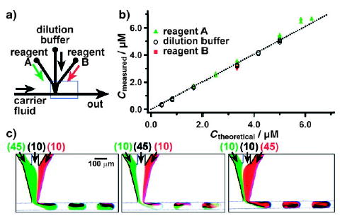
Controlling the concentrations of reagents within plugs by on-chip dilution.[44] a) Experimental setup; the blue rectangle shows the field of view for microphotographs shown in (c). b) A graph quantifying the on-chip dilution method. The concentrations measured from the fluorescence intensity of plugs traveling through the microchannel are plotted as a function of theoretical concentration calculated from the flow rates of the streams containing reagent A, the dilution buffer, and reagent B. c) The concentrations of the reagents were controlled by the relative flow rates of the reagent streams (values in parentheses, in nLs−1). Reprinted with permission from reference [44]. Copyright 2003 American Chemical Society.
This technique was also used to obtain an array of plugs, whereby each plug contained a unique composition of four reagents.[128] The composition of reagents within each plug was determined by the relative flow rates of the reagent streams, which were controlled by a computer. This capability allows rapid switching of reaction conditions without stopping the experiment or wasting valuable reagents. This approach is not limited to the geometries shown in Figure 7; it is also compatible with “flow focusing” (Figure 5) for forming droplets with controlled concentrations of reagents.
2.2.3. Direct Injection of Reagents into Droplets
For multiple-step reactions, a reaction mixture is allowed to react for a certain time and then another reagent is added to the mixture. In droplet-based microfluidics, the first step of the reaction can be contained within a plug that is transported within the microchannel. Then, a reagent for the second step of the reaction can be injected into the plug through a side channel further along the microchannel network.
A reagent flowing through a side channel can be injected directly into droplets through a T junction (as shown in Figure 6 for the injection of a target sample into an array of plugs). However, if the T junction is preferentially wetted by the carrier fluid (e.g., with a hydrophobic junction and aqueous reagents), then the injection of the reagent into a plug is favorable only at low values of the capillary number (Ca ≈ 0.01).[129,130] At higher values of Ca (for example, at higher flow rates), the injection can be accomplished by mechanical agitation of the PDMS channel.[129]
Another injection method was developed with a side channel that is preferentially wetted by the reagent fluid (e.g., with a hydrophilic channel and aqueous reagents; Figure 8a).[131,132] As a droplet is formed from the injection of reagent fluid from a side channel into the main channel, wetting of the side channel prevents this droplet from breaking off until a plug passes by the side channel, and this droplet is injected into the plug.[131] With this injection method, the volume of the reagent injected into the plug increases linearly with the flow rate of the reagent stream in the side channel (Figure 8b).[132] Cross-contamination between plugs at the T junction was quantified by fluorescence measurements and found to be minimal.[131]
Figure 8.
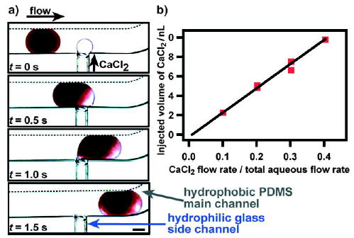
Injection of a CaCl2 solution into a plug (blood) through a hydrophilic side channel.[132] a) Time-lapse microphotographs of the injection process. b) The injection volume is controlled by the flow rate (μLmin−1) of the CaCl2 stream. Each data point on the graph denotes measurements for 10 plugs (y = 24.947x−0.2312, R2 = 0.9849). Reprinted with permission from reference [132]. Copyright 2006 American Chemical Society.
For gas–liquid slugs, the reagents need to be injected into the continuous phase, as reactions occur within this phase. Such injection is easy, as this continuous phase is always in contact with the microchannel wall. However, contamination between slugs can result, especially in rectangular microchannels. The merging of a tracer dye into the continuous phase was demonstrated for slugs within microchannels.[48]
2.3. Controlling Mixing by Chaotic Advection
The control of mixing is important for reactions and autocatalytic processes.[133,134] Rapid mixing of reagents is necessary to determine the starting time of a reaction accurately. Droplet-based microfluidics allows rapid mixing and the extent of mixing can be quantified.[1,40,135] It has been reported that for a single-phase microfluidic flow, a reagent can be mixed by hydrodynamic focusing with a large excess of a second reagent with mixing times of only 10 μs.[136] The mixing was sufficiently rapid that the time resolution of kinetic measurements was limited by dispersion and not by mixing. Chaotic advection in a staggered herringbone mixer[137] was used to achieve complete mixing of two reagents in milliseconds and to reduce dispersion. This idea of chaotic advection (see Figure 9 and a movie in the Supporting Information) was implemented with droplets.[1,40,46] Chaotic advection[137–139] relies on repeated folding and stretching of the two fluids to achieve layers of fluids (striations) that become exponentially thinner and thinner (Figure 9) until mixing by diffusion becomes rapid. Mixing in droplets by chaotic advection can be achieved in sub-millisecond times[40] without dispersion and is especially useful when both mixing on a short timescale and dispersion over a longer timescale need to be controlled.
Figure 9.
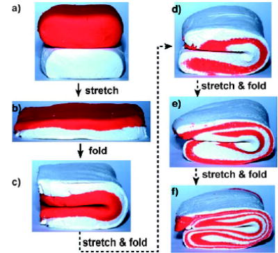
Model for the mixing of two reagents by chaotic advection at low values of the Reynolds number; photographs of two layers of modeling clay being stretched and folded. Images are courtesy of Joshua D. Tice.
Droplets traveling through a microchannel experience internal recirculation, which has been used to enhance mixing in plugs[37,140–143] and slugs.[46,50,144–146] In straight channels, two symmetric vortices form on the left and right halves of a plug (in the direction of plug movement, Figure 3). The mixing occurs by convection within each half and mainly by diffusion between the two halves of the plug. In winding channels (Figure 10), the interface between the two halves of the plug is reoriented from the direction of plug movement and is stretched and folded by recirculations (Figure 10). This technique greatly enhances mixing (see two movies in the Supporting Information for a comparison of mixing in straight and winding channels).
Figure 10.
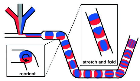
Mixing by chaotic advection in a plug moving through a winding channel. The interfaces between the red and blue fluids are reoriented, stretched, and folded as the plug moves through the corners and straight sections of the channel. Reprinted with permission from reference [40]. Copyright 2003 American Institute of Physics.
The extent of mixing is dependent on the number of winding turns and can be quantified by analyzing fluorescence images (Figure 11b). By using a “bumpy” mixer (Figure 12) to generate oscillating shear within plugs, even viscous biological samples containing high concentrations of bovine serum albumin or hemoglobin can be mixed within milliseconds.[45] The striations (Figure 12c) observed in this mixer are astonishingly similar to those expected for chaotic advection (Figure 9, Figure 10).
Figure 11.
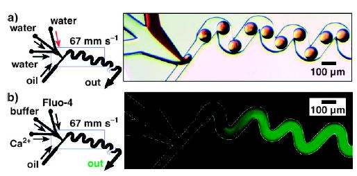
Rapid mixing in droplets by chaotic advection.[40] Left: Schematics of the microfluidic network. Right: a) Bright-field and b) fluorescence microscopy images of plugs moving through winding channels. The observed fluorescence is a time average of the fluorescence of many plugs passing through the field of view throughout the 2-s exposure time. The mixing was quantified by using the fluorogenic substrate Fluo-4, whose fluorescence increases upon binding to Ca2+. Figure reprinted with permission from reference [40]. Copyright 2003 American Institute of Physics.
Figure 12.
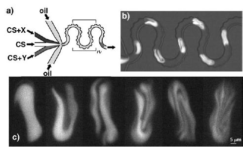
Mixing of viscous solutions in plugs with a bumpy mixer.[45] a) Schematic of the bumpy serpentine mixer; CS: crowded solutions, X and Y: reagents. b) Mixing of plugs containing bovine serum albumin (BSA, 200 mgmL−1) and a calcein dye. c) Images of the striations observed inside the plugs during mixing of a hemoglobin solution (300 mgmL−1) with a BSA solution (260 mgmL−1 with 5 mM calcein). Figure reprinted with permission from reference [45]. Copyright 2006 American Chemical Society.
2.4. Control of the Interfacial Chemistry
In microfluidics, surface effects are important because of the high surface-area-to-volume ratio. Surface effects can appear at the interface between the solid microchannel wall and the fluid (solid–liquid) or between the two immiscible fluids in the microchannel (liquid–liquid). For a molecule within a droplet, interactions at the liquid–liquid interface become especially important as the dimension of the droplet approaches Γmax/C0, in which Γmax (mol m−2) is the maximum surface coverage of the interface that can be achieved at saturating concentrations of the molecule and C0 (mol m−3) is the initial concentration of the molecule. A recent review article illustrates how interfaces between fluids and interactions in fluids can be controlled by microfluidics.[119] These interactions can be used to concentrate solutes within the droplets,[147] to maximize efficiency of a catalyst embedded on the surface of a microchannel,[104] and to synthesize coated particles by interfacial reactions.[112,117] A high surface-area-to-volume ratio ensures rapid heat transfer between plugs and the carrier fluid and allows rapid switching between different temperatures. This rapid switching is essential for DNA amplification,[148] in vitro protein expression in plugs,[149] and DNA analysis.[51]
Interactions at solid–liquid and liquid–liquid interfaces in a microchannel can be advantageous for certain applications yet detrimental for others. Therefore, these interactions need to be controlled. For plugs, the reaction occurs within the dispersed phase, which does not come in contact with the solid microchannel wall but is encapsulated by a layer of the carrier fluid. Therefore, reactions within plugs will be affected by the surface chemistry at the liquid–liquid interface. For slugs, the reaction occurs within the continuous phase, which is in contact with both the solid microchannel and the dispersed phase. Therefore, reactions within slugs will be affected by the surface chemistry at both the solid–liquid and liquid–gas interfaces.
To form plugs in microchannels, the surface of channels should be treated to ensure that the carrier fluid (and not the aqueous phase) preferentially wets the channel wall. The surface tension between the aqueous phase and the carrier fluid should be lower than the surface tension between the aqueous phase and the channel wall. Surfactants can be used within the carrier fluid to lower the surface tension between the aqueous phase and the carrier fluid. However, this surface tension should not be lowered too far as the capillary number Ca of the flow must be low to favor the formation of plugs;[38] the capillary number is defined as Ca = μU/γ, in which μ (kgm−1s−1) is the viscosity of the fluid, U (ms−1) is the flow rate and γ (Nm−1) is the interfacial tension between the aqueous phase and the carrier fluid.
Perfluorinated liquids are optimal carrier fluids for the formation of plugs. They are considered to be chemically and biologically inert and have been used as blood substitutes,[150] for liquid ventilation of fetuses,[151] for diagnostic ultrasound imaging,[152] for cell cultures,[153,154] and in drug delivery.[155] Many types of fluorocarbons and fluorinated surfactants are commercially available (however, recent evidence shows that some fluorinated surfactants may accumulate in tissues,[156,157] and therefore such surfactants should be handled with care). Also, fluorocarbons and fluorinated surfactants provide an orthogonal chemistry to reactions conducted in organic phases.[158]
Fluorinated surfactants can be used to control the surface chemistry at the liquid–liquid interface between the aqueous phase and the fluorinated phase,[43] in a similar manner to how hydrocarbon surfactants are used to block adsorption at the interface between aqueous and hydrocarbon phases.[159–161] Fluorinated surfactants are insoluble in the aqueous phase and arrange themselves at the interface between the aqueous and fluorous phases. Plugs are encapsulated in a thin layer of carrier fluid, so different surface properties can be obtained by simply changing the surfactant in the fluorous carrier fluid without requiring functionalization of the microchannel wall. The adsorption of fibrinogen within a plug was controlled by using this method (Figure 13). A surfactant with a carboxylic acid group resulted in adsorption (Figure 13a), whereas a surfactant with an oligoethylene glycol group prevented adsorption (Figure 13b).
Figure 13.
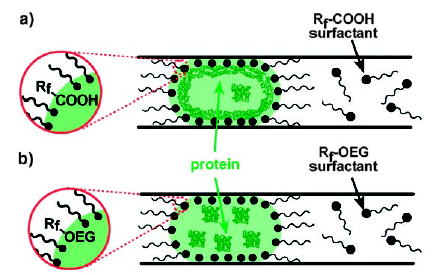
Control of the surface behavior of plugs with surfactants at the interface between the aqueous and fluorous phases. a) A COOH surfactant with a fluorinated side chain (Rf ) provides a non-inert interface that is prone to protein adsorption. b) A surfactant with a fluorinated side chain and a polar oligoethyleneglycol (OEG) head group provides an inert, biocompatible interface. Reprinted with permission from reference [43]. Copyright 2005 American Chemical Society.
2.5. Combining and Splitting Reactions
To perform a multiple-step reaction, reaction mixtures must be combined and split in a controlled manner. By using droplet-based microfluidics, a range of interactions between reactions can be controlled in time.[1] Reactions can be combined by merging two droplets, and reactions can be split by splitting one droplet into two smaller droplets (Figure 14).[1,162]
Figure 14.
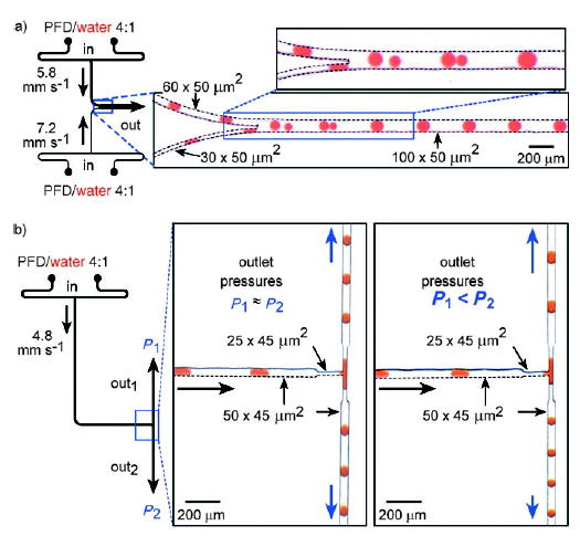
Merging and splitting of droplets in microchannels.[1] Left: Schematic of the microfluidic network. Right: Microphotographs of plugs traveling through the microchannel. a) Spontaneous merging of pairs of plugs into single plugs in the main microchannel. b) Spontaneous splitting of plugs at the branching point in a microchannel. When the outlet pressures are equal, a stream of plugs splits into plugs of approximately half the volume of the initial plugs (middle). When the outlet pressures are different, asymmetric splitting of plugs is observed (right). Perfluorodecalin (PFD) serves as the carrier fluid. Reprinted from reference [1].
Various methods have been developed for merging and splitting droplets. To combine two parallel reactions, two sets of droplets can be formed in two parallel microchannels that converge into one main channel. The two sets of droplets will merge within the main channel if the frequency is matched between the two droplets and the droplets are of different sizes (Figure 14a).[1] The merging of several smaller droplets with a single larger droplet[163] and of two droplets of the same size has also been shown.[164] The splitting of droplets in a constricted T junction (Figure 14b)[1,125] and at isolated obstacles has also been studied.[165]
Numerous studies have investigated how droplets can be manipulated and controlled within microchannels;[166] examples include the sorting of droplets with dielectrophoretic forces,[167] the control of droplet volume, chemical concentrations, and sorting of droplets,[168] as well as numerical studies on the deformation, breakup, and coalescence of droplets.[110,130,169] A method was developed recently that uses electric forces to combine and split droplets in microchannels. In this method, two streams of droplets are produced, and opposite charges are applied to the interfaces of aqueous and carrier fluid (Figure 15); the two streams are synchronized and combine completely in a 1:1 ratio upon confluence.[170a] Neutral droplets could be recharged by splitting each droplet into two droplets of opposite charge.[170a] Charged droplets were also sorted by means of electric interactions.[170a] Another method used alternating current field to control the coalescence of plugs.[170b] These techniques should be useful for developing automated, droplet-based microfluidic platforms.
Figure 15.
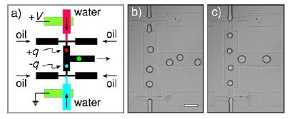
Coalescence of drops by means of electric forces.[170a] a) Drops with opposite signs of electrostatic charge could be generated by applying a voltage across the two aqueous streams. b) In the absence of an electric field, the frequency and timing of drop formation at the two nozzles are independent even at identical infusion rates. In the presence of surfactant, the drops did not coalescence upon confluence of the two streams (scale bar: 100 μm). c) With an applied voltage of 200 V (separation of the nozzles: 500 μm), the drops broke off from the two nozzles simultaneously and coalesced upon confluence. Reprinted with minor modification from reference [170a].
2.6. Indexing Reaction Conditions by Means of Droplet Pairs
Indexing of droplets is important when many droplets, each containing different reactants, are involved. One possibility is to add reporter dyes at concentrations that are correlated with those of the reagents in the droplet. To avoid possible interference of the reaction by the reporter dyes, pairs of droplets can be produced, one in which the reaction is performed and the other for carrying the information (Figure 16).[33,41] Information about the reaction conditions can be spatially organized with these pairs of droplets—one droplet contains the reaction mixture, the other contains dyes whose ratiometric intensity reports the ratio of reagents within the first droplet.[33,41]
Figure 16.
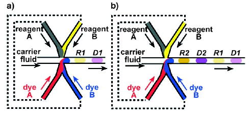
The concentrations within the droplets can be indexed by producing alternating droplets within the microchannels.[41] Pairs of droplets R and D are formed; droplet R contains the reagents, and droplet D contains dyes for indexing. The flow rates of reagent A and dye A and of reagent B and dye B are correlated (indicated by the dashed lines). a) The concentrations of reagents A and B in R1 are correlated with the concentrations of dyes A and B, respectively, in D1, so that the concentrations of dyes A and B in D1 can be used to index the concentrations of reagents A and B in R1. b) An array of alternating droplets. Reprinted with permission from reference [41] with minor modifications. Copyright 2004 American Chemical Society.
Droplets within microchannels can be generated with alternating compositions (XYXY…). A pair of droplets consists of a droplet of composition “X” and a droplet of composition “Y”. The formation of alternating droplets in microchannels was characterized as a function of the capillary number and the flow rates of the aqueous and carrier-fluid streams.[41] A movie of alternating droplets forming in a microchannel can be found in the Supporting Information.
2.7. Analysis of Droplet Contents
There are two methods of analyzing the composition of the reaction mixture and the progress of the reaction within droplets: either each droplet can be analyzed individually or a single measurement can be made of many droplets.
Analysis of the contents of a single droplet requires the handling of a small volume of sample (typically from femtoliters to microliters). Fluorescence is used most often for analysis within microfluidic devices, in which case the contents of a single droplet are detected by using a fluorogenic substrate. Electrophoresis has been used in integrated microfluidic devices.[51] Recently, MALDI-MS was used for semiquantitative characterization of deacetylation reactions in nanoliter-sized plugs.[126] Also, microcoil NMR spectroscopy can be used to analyze small samples.[171] X-ray diffraction has also been used to analyze single protein crystals within a plug.[34]
Measurements on multiple droplets can be made either outside or within the microfluidic device. For external analysis, droplets can be collected into vials until there is sufficient volume for analysis. This method is typically used for nanoparticle synthesis, the characterization of which requires absorbance measurements, SEM, and similar methods. For on-chip analysis, time-resolved measurements can be obtained from a single spatially resolved fluorescence microphotograph (such as that in Figure 11b).[1,44] The fluorescence intensity is linearly related to the formation of the cleavage product. As dispersion is absent, the amount of product formed at time t can be determined by measuring the fluorescence intensity within the microchannel at distance d (Figure 17). Kinetics can be measured with this method on a millisecond timescale with nanoliter volumes of reagents.[44]
Figure 17.
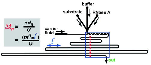
Kinetic measurements by analysis of a single microphotograph of droplets traveling through a microchannel.[44] The red points indicate time points tn, and the blue rectangle outlines the field of view for the fluorescence microphotograph. The reaction being measured within the droplets should result in a change in fluorescence (as in Figure 11b). The time course of the reaction can be obtained by measuring the fluorescence intensity at each position (red circles) within the microphotograph. The equation shown enables the time difference between each point to be determined; Δtn [s] is the time interval between n = 1 to 8 (for each row of microchannel in the field of view), m = 1.5, l = 0.9 mm, U = 106 mms−1. Reprinted with permission from reference [44]. Copyright 2003 American Chemical Society.
3. Applications of Droplet-Based Microfluidics
The techniques described above have been applied to many different types of reactions, performed in parallel as well as in series. We divide these reactions into five categories: 1) enzyme kinetics, enzyme assays, and DNA analysis; 2) protein crystallization; 3) synthesis of molecules; 4) synthesis of nanoparticles, microparticles, and colloidal assemblies; 5) synthesis of reaction networks.
3.1. Enzyme Kinetics, Enzyme Assays, and DNA Analysis
3.1.1. Enzyme Kinetics within Droplets
The rapid mixing (Section 2.3), the biocompatible interfacial chemistry (Section 2.4), and the absence of dispersion make droplet-based microfluidics the method of choice to measure single-turnover kinetics of the enzyme ribonuclease A (RNase A) with millisecond resolution (Figure 18).[44] By using on-chip dilution (Section 2.2.2), serial measurements of the kinetics of RNase A turnover were performed for three substrate concentrations (Figure 18b). A kinetic trace is obtained from a time-averaged image of the fluorescence intensity (Section 2.7); each kinetic trace required approximately 66 nL of sample. The conversion of alkaline phosphatase was also studied within plugs on a millisecond timescale.[43] The activity of luciferase within droplets of viscous solutions could be studied with millisecond resolution by using the “bumpy mixer” (Figure 12a).[45] Control of dispersion enables plugs to be used to perform enzymatic reactions on slower timescales (from seconds to hours). A multiple-step assay to measure the clotting time of blood was adapted to the droplet-based microfluidic system, which allowed fibrin clots within the droplets to be transported through the channel without contacting or contaminating the channel walls.[132] By using a preformed cartridge containing plugs of various enzymes (Section 2.2.1) and by merging these plugs with a stream of a substrate (Figure 6), enzymes could be screened to identify an enzyme with desired reactivity.[42]
Figure 18.
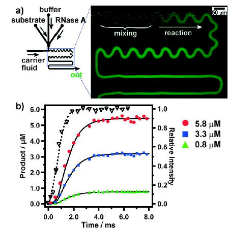
Kinetic analysis on a millisecond timescale of the turnover of RNase A in plugs.[44] a) Left: Experimental setup. Right: Fluorescence microphotograph (false-colored) that shows the time-averaged (exposure time 2 s) intensity of aqueous plugs and carrier fluid moving through the microchannel. b) Graph of the experimental kinetic data for three substrate concentrations at 0.8 (▴), 3.3 (▪), and 5.8 μM (•); the data is obtained from analysis of images such as that in (a). Also shown is a mixing curve (right axis, ▽) for a Fluo-4/Ca2+ system in the same microfluidic device. The solid lines are fits of the reaction progress including explicit treatment of mixing. Reprinted with permission from reference [44]. Copyright 2003 American Chemical Society.
Microreactors for in vitro protein expression are useful for directed evolution of proteins, because the genes and substrate for the protein can be contained in the same microreactor to express the protein and probe its function simultaneously.[61,149] In a microfluidic device, droplets of sub-picoliter volume were formed from two aqueous streams (Section 2.2.2) containing the components for GFP expression (GFP-encoding vector, RNA polymerase, amino acids, nucleotides, and ATP; GFP = green fluorescent protein).[149] After incubation of the droplets at 37°C, the expression of GFP was confirmed by high-sensitivity epifluorescence microscopy (Figure 19).[149] This method, which allows easy control of the concentrations of a large number of droplets (Section 2.2.2), demonstrates the potential application of droplet-based microfluidic channels for the directed evolution of proteins.
Figure 19.
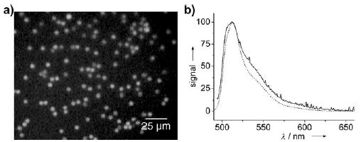
In vitro translation of GFP within droplets.[149] a) Fluorescence microphotograph of the droplets after GFP expression. The droplets were collected in a microfabricated well. b) Fluorescence spectrum of GFP; dashed line: commercially obtained protein in aqueous solution, solid line: individual droplet after in vitro expression. Reprinted from reference [149].
3.1.2. Encapsulation of Macromolecules and Cells in Droplets
Cell cultivation can be highly parallelized with droplet-based microfluidics, as has been demonstrated for C. elegans embryos[172] and microbial cells.[162,173,174] By confining a cell within a droplet, dilution is minimized, and the small amounts of molecules released by the cell can be more easily detected.
Single-cell enzymatic assays have been achieved by encapsulating single cells inside droplets.[175] A single droplet of controlled femtoliter volume could be generated by using specially designed T channels. Before the formation of the droplet, a single cell was selected from the aqueous solution and moved by optical trapping to the interface between the aqueous phase and the carrier fluid.[175] The cell was encapsulated in the resulting droplet. Similar selective encapsulation has been demonstrated for polystyrene beads, single cells, and single mitochondria.[175] In one example, a single mast cell was encapsulated in a droplet containing a fluorogenic substrate outside the cell (Figure 20a). Before photolysis of the cell, the droplet appeared dark under the fluorescence microscope (Figure 20b). After photolysis of the cell (Figure 20c), the intracellular enzyme β-galactosidase was released and cleaved the fluorogenic substrate, and thus the droplet became fluorescent (Figure 20d).[175] In a microfluidic device with integrated heaters and coolers, slugs were used for cells lysis and for detection of the transient responses of the MAPK signaling pathway.[176]
Figure 20.
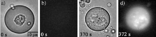
An enzymatic assay for a single mast cell within a droplet.[175] a, c) Brightfield images; b, d) fluorescence images. Reprinted with permission from reference [175]. Copyright 2005 American Chemical Society.
Recently, microfluidic droplets were also used to generate lipid vesicles encapsulating biological macromolecules or cells. Aqueous droplets were first generated by using oleic acid containing phospholipids as the carrier fluid (continuous phase).[177] This water–lipid emulsion was subsequently injected into an EtOH/H2O mixture to extract the oleic acid, and the phospholipids rearranged to form vesicles.[177] Encapsulation of biological molecules or cells was achieved by using an aqueous solution containing the encapsulation targets to generate the initial droplets (Figure 21).[177] Cells encapsulated in vesicles with this method remained viable for 2 hours.[177] This approach is a single-step process and does not require toxic solvents.[177]
Figure 21.
Fluorescence microscopy of a) GFP encapsulated in DOPC vesicles; b) a single Hela cervical carcinoma cell (diameter 10 μm) encapsulated in a DOPC vesicle; c) MCF7 breast cancer cell encapsulated in a DMPC vesicle. Reprinted from reference [177]. Copyright 2006 American Chemical Society. DOPC = dioleoylphosphatidylcholine, DMPC = dimyristoylphosphatidylcholine.
3.1.3. DNA Analysis
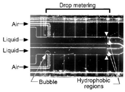
The use of slugs as microreactors was nicely illustrated by an integrated DNA analyzer.[51] This device measures and handles nanoliter volumes of solutions in slugs. A hydrophilic microchannel with a hydrophobic patch on its surface is filled by capillary action with an aqueous solution (of the sample or reagent) until the solution reached the hydrophobic patch (Figure 22).[51,178] An air bubble is then generated by pressure to split off a liquid slug of nanoliter volume and to move it through the channel (Figure 22). The sample and reagent slugs are subsequently combined and heated in the reaction chamber. When the reaction is finished, the slug is moved by pressure to an electrophoresis channel for on-chip separation and detection. Polymerase chain reaction of DNA has also been performed in continuous flows of slugs[148a,b] and plugs.[148c]
Figure 22.
Optical microphotograph of the liquid-injection part of an integrated DNA analyzer. Reprinted from reference [51]. Copyright 1998 AAAS.
3.2. Protein Crystallization with Droplet-Based Microfluidics
Growing high-quality crystals is an important step in solving protein structures by X-ray crystallography. Crystals are typically grown by using the microbatch method or the vapor-diffusion method. In microbatch methods, a microliter-sized drop containing precipitants and the protein sample is incubated under a layer of oil. In vapor-diffusion methods, a microliter-sized drop containing precipitants and the protein sample is placed next to a reservoir containing a high concentration of desiccant. In this method, water evaporates from the drop into the reservoir, which increases the concentration of the supersaturated solution within drop and promotes the nucleation and growth of crystals.
Protein samples are usually available in only limited amounts. Therefore, strategies have been developed to miniaturize these processes by using either robotics[179,180] or microvalve-based microfluidics.[24–26] Droplet-based microfluidics allows the use of nanoliter-sized droplets, so a thousand crystallization trials can be set up with approximately 10 μL of protein sample. In this section, we discuss how droplets can be used to conduct both microbatch and vapor-diffusion methods of crystallization, to perform on-chip X-ray diffraction, and to study the effect of mixing on the nucleation and growth of protein crystals.
3.2.1. Protein Crystallization by Sparse-Matrix and Gradient Screening
The growth of crystals of a protein with the microbatch method usually involves two steps. First, a large number of crystallization reagents (a particular combination of buffer, precipitants, and polymer solution) are tested with the protein to identify the appropriate combinations of reagents that produce protein crystals (sparse-matrix screening). Then, the concentration of each reagent in the combination is finely screened to grow crystals of diffraction quality (gradient screening).
Sparse-matrix screening was performed with droplet-based microfluidics by introducing the protein sample into a preformed cartridge containing an array of crystallization reagents (Section 2.2.1).[42] The plugs in the cartridge were combined with a stream of thaumatin protein through a T junction, transported into a glass capillary, sealed, and finally incubated to allow crystals to grow. These trials could be stored in glass capillaries for more than half a year without evaporation.[42] Protein crystals grown in the capillaries were detected with a bright-field microscope equipped with a polarizer.
Gradient screening was performed by using a computer program to control the flow rates of the reagents to produce an array of droplets (Figure 23).[128] The concentrations of the reagents were varied by changing the flow rates of the reagents (Section 2.2.2). After setting up the gradient screen, the flow of reagents was stopped and the array of droplets was incubated to determine the appropriate crystallization conditions for the protein.
Figure 23.
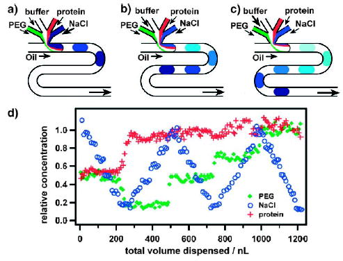
Gradient screening of protein crystallization conditions in droplets.[128] a–c) The concentrations of the crystallizing reagents (PEG, buffer, protein, and NaCl) are varied by varying the relative flow rates of the reagents. d) Experimental characterization of the gradient screen. Two droplets with volume of 7.5 nL were formed each second; each data point represents one droplet. Reprinted with permission from reference [128]. Copyright 2003 American Chemical Society.
3.2.2. Protein Crystallization by Vapor Diffusion
In the vapor-diffusion method of crystallization, the diffusion of water vapor from a drop containing the crystallization reagents is accelerated by a reservoir containing a solution of a desiccant (e.g., a concentrated salt solution). To implement this method in droplet-based microfluidics, pairs of alternating plugs (Section 2.6) were formed in which one droplet contained a mixture of protein and precipitant, and the other droplet contained a concentrated salt solution (Figure 24).[34] To allow water to transfer between plugs, a water-permeable carrier fluid was used to form the plugs.
Figure 24.
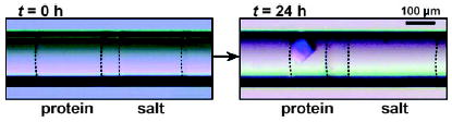
Protein crystallization by the vapor-diffusion method by using alternating droplets.[34] Microphotographs of a pair of alternating droplets at 0 h (left) and at 24 h (right) after the droplets were transported into the capillary. A crystal formed within the droplet of the protein solution after the volume of the droplet decreased by 50%. Dashed lines indicate the interfaces between the aqueous droplets and the carrier fluid. Reprinted from reference [34].
3.2.3. Protein Structure Determination by On-Chip X-ray Diffraction and In Situ Structure Solution
Before X-ray diffraction data can be obtained, the crystals must be transferred from the mother liquor, soaked with cryoprotectant, frozen, and finally mounted onto an X-ray diffractometer. Handling these crystals is often not trivial. By growing crystals in plugs inside X-ray-transparent capillaries, the diffraction pattern of a thaumatin crystal was obtained directly (Figure 25).[34]
Figure 25.
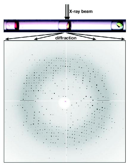
On-chip X-ray diffraction of thaumatin crystals within a capillary.[34] Reprinted from reference [34].
As crystals are easily damaged by X-ray radiation, it is difficult to obtain a complete set of data from one crystal without freezing the crystal. By growing multiple crystals in a capillary and merging the data from each crystal, a complete data set was obtained. This concept of “in situ structure solution”[181] has been demonstrated for model proteins within plugs.[182] It will be important to establish whether this method can be used as a general approach for determining the structure of a broad range of proteins.
3.2.4. Influence of Mixing on Protein Crystallization
Mixing has been presumed to be a cause of inconsistencies in batch crystallization. In typical benchtop procedures, mixing is not well controlled, and the effect of mixing is difficult to study with conventional pipetting methods. As mixing can be controlled within plugs (Section 2.3), the effect of mixing on the nucleation of protein crystals within plugs can be studied (Figure 26).[183] The rate of nucleation increases rapidly (exponential squared) with increasing concentration above supersaturation (related to the concentrations of the protein and the precipitant). Because precipitants (often small molecules or salts) may diffuse faster than the protein, the solution at the interface between the solutions of the protein and the precipitant is more supersaturated than the solution after mixing. Mixing was used to control the lifetime of the interface between the solutions of protein and salt in plugs. If mixing was slow, then the lifetime of the interface was long and excessive nucleation resulted (Figure 26b). If mixing was fast, then the lifetime was short and fewer nucleation events resulted (Figure 26c).
Figure 26.
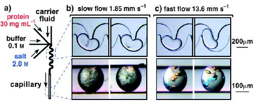
Study of the influence of mixing on the nucleation of protein crystals by using droplets.[183] a) Experimental setup. b) At a low flow rate, precipitation was observed (top image); precipitate and microcrystals grew within the plugs (bottom image). c) At a higher flow rate, fewer and larger crystals were observed (bottom image). Reprinted with permission from reference [183]. Copyright 2005 American Chemical Society.
3.3. Syntheses in Droplets
3.3.1. Synthesis of Organic Molecules in Droplets
Organic reactions have been performed in microfluidic plugs and slugs to exploit the advantages of miniaturization as well as facile heat and mass transfer. Examples of single-step reactions that have been performed within plugs include the nitration of benzene,[184–186] the extraction of acid from kerosene,[187] the fluorination of aromatics,[49] the bromination of alkenes,[188] and precipitate-forming reactions.[189] Monomeric and novolak azo dyes were formed within plugs in a two-step reaction.[47] The hybridization efficiency on DNA microarrays was improved by segmenting the samples into slugs.[190]
Mass transport is crucial for heterogeneous reactions that occur between multiple phases. In droplet-based microfluidics, effective and well-controlled mass transport between phases can be achieved[96] thanks to the reproducible flow patterns. This enables droplet-based microfluidics to be used as a tool for investigating the effect of mass transport on heterogeneous reactions. One example of this application is the catalytic hydrogenation of unsaturated aldehydes, in which three phases were involved: the aqueous phase contained the [RuII(tppts)] catalyst (tppts = triphenylphosphane trisulfonate), the organic phase contained the unsaturated aldehyde, and the gas phase was composed of H2. The reaction was conducted in capillaries by forming alternating (Section 2.6) aqueous droplets and H2 bubbles in an organic solvent, which served as the carrier fluid (Figure 27).[191] The mass transfer between phases was controlled by the flow rates and the diameter of capillary. This study suggested that the mass transport is the rate-determining factor of the reaction.[191]
Figure 27.
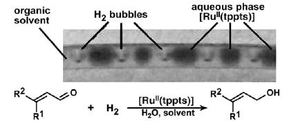
Catalytic multiphase reaction for the hydrogenation of unsaturated aldehydes performed by using alternating droplets.[191] Photograph of a capillary (diameter 750 μm) containing alternating H2 bubbles and aqueous droplets. The continuous phase is an organic solvent (either toluene or hexane) that contains the unsaturated aldehyde. Figure reprinted from reference [191].
Minimization of the reagent consumption is an important factor for optimizing reactions of precious substrates. The consumption of substrates per reaction can be decreased to nanoliter volumes by conducting these reactions in plugs. A preformed cartridge (Section 2.2.1) containing different reaction conditions (Figure 28) was used to optimize an organic reaction,[126] and the plugs from the cartridge were merged (Section 2.2.3) with a stream of the substrate solution. In the selective deacetylation of the substrate hexaacetyl ouabain (Ac6-OUA), less than 1 μg of Ac6-OUA was required for each reaction. In contrast to screening in microtiter plates, this plug-based method requires only two syringe pumps for flow control. Evaporation is also eliminated. MALDI-MS was used as a semiquantitative detection method to analyze the reaction in the nanoliter-sized droplets (Figure 28b).[126]
Figure 28.
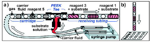
Testing of the conditions of organic reactions in plugs with subsequent analysis by MALDI-MS.[126] a) Setup for serial merging of the reagent plugs with a stream of substrate solution. “PEEK Tee” is a commercially available T junction. b) The reaction plugs are deposited on a MALDI plate for analysis. Figure reprinted from reference [126]. Copyright 2006 American Chemical Society.
3.3.2. Synthesis of Monodisperse Nanoparticles
In addition to kinetic measurements, the synthesis of monodisperse polymers and particles also requires accurate control of the reaction time. Compartmentalization and rapid mixing (Section 2.3) result in a defined starting point of reactions and a narrow distribution of residence times. This control of mixing enabled, for example, the synthesis of silica gel particles of uniform size within liquid slugs.[192] The size of the nanoparticles was controlled by varying the flow rate and therefore the residence time (Figure 29).[48,129,192] The reproducible synthesis of CdSe nanocrystals at elevated temperatures was achieved within both slugs[116a] and plugs[116b] in microfluidic devices.
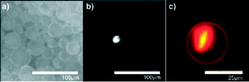
Figure 29.
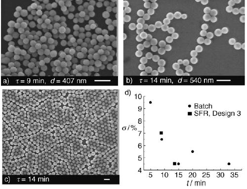
Synthesis of monodisperse particles of silica gel with a segmented-flow reactor (SFR).[192] Various residence times τ resulted in silica particles with different average diameters davg. SEM microphotographs are shown for a) τ = 9 min, davg = 407 nm, and b) τ = 14 min, davg = 540 nm. c) Low-magnification SEM image of sample shown in (b). d) Standard deviation of the mean diameter σ versus τ for particles formed by using an SFR or a batch reactor. Reprinted with permission from reference [192]. Copyright 2004 American Chemical Society.
A multiple-step synthesis of CdS and CdS/CdSe core–shell nanoparticles was demonstrated within plugs in a PDMS device. By using a merging junction (Section 2.2.3) to deliver a quenching reagent, the nanoparticles were more monodisperse than those produced without the quenching step (Figure 30).[129] The quenching step also allowed core–shell particles to be synthesized.
Figure 30.
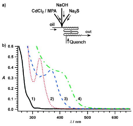
Multiple-step synthesis of nanoparticles in droplets on a millisecond timescale.[129] a) Experimental setup. b) UV/Vis spectra of four types of CdS nanoparticles; reaction conditions: 1) CdCl2/Na2S 20:1, quench with methylpropionic acid (MPA) (black); 2) CdCl2/Na2S 10:1, quench with MPA (red); 3) CdCl2/Na2S 1:1, quench with Na2S (blue). 4) CdS/CdSe core–shell nanoparticle, synthesized using CdCl2/Na2S 1:1 with Na2Se quenching (green). Reprinted with permission from reference [129]. Copyright 2004 The Royal Society of Chemistry.
3.3.3. Synthesis of Microparticles with Controlled Morphology
Microparticles with uniform morphology are important in drug delivery, electrooptic devices, and catalysis.[193] Most methods for the synthesis of these particles[117,194] are either expensive or specific to only a particular type of material with controlled morphology.[195] As droplets produced in microfluidic devices are uniform in size and shape, they can be used to study the self-assembly of gel emulsions[196] and colloidal particles into three-dimensional[197] and periodic two-dimensional[198] structures. Trapping these uniform droplets by either interfacial polymerization or bulk solidification is a practical alternative to the existing methods for synthesis of particles with micrometer dimensions.
Uniform capsules (Figure 31a) were synthesized by forming droplets with an axially symmetric flow-focusing device, in which the dispersed phase was an aqueous solution of 1,6-hexanediamine and the continuous phase was hexadecane with adipoyl chloride.[117] Polymerization of 1,6-hexanediamine and adipoyl chloride at the interface between the aqueous and the hexadecane phase generated a semi-permeable membrane (Figure 31c) of nylon-6,6 coating the aqueous droplets.[117] The diameter of the capsules could be controlled by adjusting the flow rates of the dispersed and continuous phases. It is possible to introduce novel functionality by adding micro- or nanoparticles to the dispersed phase. For example, by incorporating superparamagnetic iron oxide nanoparticles into the aqueous solution, the resulting capsules can be manipulated under a magnetic field (Figure 31b).[117] Semipermeable polyamide capsules have been synthesized by means of a droplet-generating device, which was produced without microfabrication methods.[112] Capsules have been formed by encapsulating yeast cells inside droplets and polymerizing the outer shell of the droplet.[199]
Figure 31.
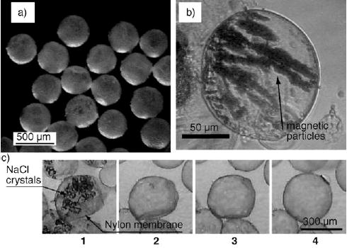
Nylon-coated aqueous droplets generated by interfacial polymerization at the liquid–liquid interface of droplets.[117] Top: a) Capsules with narrow size distribution formed with an axially symmetric flow focusing device. b) Capsules containing magnetic particles that align in an induced magnetic field. c) Capsules containing NaCl were dehydrated by adding ethanol (frame 1). As ethanol was exchanged for water, the membrane swelled over time (frames 2–4). After 30 s, the capsules were fully swelled (frame 4). Reprinted from reference [117].
Solid particles with controlled shape can be fabricated in two steps by first generating uniform droplets of the desired shape in a microfluidic device and then solidifying the content of the droplet. As the morphology of droplets is determined only by the physical properties of the fluids and operating conditions (device geometry and flow rates), this method is a general way to synthesize particles of a variety of materials with dimensions on the micrometer scale. By increasing the flow rate of the dispersed phase, the volume of the droplet is increased, and the shape of the droplet changes from spheres into nonspherical shapes that touch the walls of the microchannel. The droplets could be solidified by photoinduced polymerization, thermally induced gelation, or through a liquid–solid phase transition. Monodisperse particles with a range of morphologies (spherical, cylindrical, and rod-shaped) were synthesized by various methods of solidification with this method (Figure 32).[194] With similar or modified methods, monodisperse polymer particles were synthesized with different functionalities, including nonspherical particles,[200] molecularly imprinted polymer beads,[201] particles with novel core–shell structures,[195] particles containing immobilized biocatalyst,[202] bicolor beads,[203,204] and particles of biodegradable microgels.[205]
Figure 32.
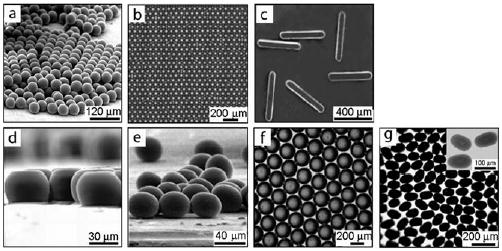
Monodisperse particles with controlled shape and sizes generated in droplets.[194] a) Polymer microspheres, b) a crystal of polymer microspheres, c) polymer rods, d) polymer disks, e) polymer ellipsoids, f) agarose disks, and g) bismuth alloy ellipsoids. Reprinted from reference [194].
Double emulsions are droplets that contain smaller droplets within them. Their potential applications range from food science to pharmaceutics.[206] Monodisperse double emulsions and core–shell structures of various sizes and internal composition have been fabricated by means of droplet-based microfluidics.[206–208] By using a flow of alternating droplets (Section 2.6), double emulsions containing two droplets of different composition were formed (Figure 33).
Figure 33.
Formation of double emulsions by encapsulation of alternating droplets.[206] Alternating red and blue droplets were formed (a, b) and transported through the microchannel (c) to another droplet-forming region. Double emulsions that contained one red and one blue droplet were formed (d). Reprinted with permission from reference [206]. Copyright 2004 American Chemical Society.
3.4. Synthesis of Functional Reaction Networks
A number of biological functions (e.g., self-regulation, energy conversion, and amplification) are performed by networks of interacting enzymatic reactions. Such functional networks of chemical reactions are nonequilibrium systems, and synthesizing them is an exciting challenge for chemists. Microfluidic droplets provide an opportunity to maintain reactions away from equilibrium by using fluid flow to supply reagents and remove products. Reactions can also be controlled so that they occur “at the right place and the right time”.
A reaction network that displays signal amplification with a threshold response has been synthesized by using plugs to compartmentalize an autocatalytic reaction and to control the interactions between reactions. The oxidation of a Co3+ complex by KHSO5 produces Co2+ ions, which catalyze the reaction and therefore their own production (Figure 34a).[163] Oxidation of the ligand leads to dissociation of the complex and liberation of the unstable Co3+ ion, which is subsequently reduced by the by-products of the ligand oxidation reaction. Without Co2+ ions, the reaction proceeds at a very low initial rate, but this reaction mixture is far from equilibrium and unstable. Because the reaction is autocatalytic, once the concentration of Co2+ accumulates to a certain level, the reaction accelerates rapidly and is complete within a short period of time. Thus, the transition time required for all of the Co3+ complex to be converted into Co2+ ions decreases with increasing initial Co2+ concentration.
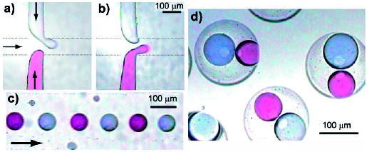
Figure 34.
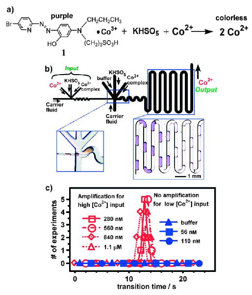
Signal amplification with a reaction network that relies on a droplet-based microfluidic system.[163] a) Autocatalytic formation of the Co3+ complex 1. b) Schematic of the microfluidic device for two-stage amplification. The first stage of the reaction takes place in the thinner channels. The second stage takes place in the thicker channels. Left: Microphotograph of the merging junction, where small droplets of a red solution merge with larger ones. Right: Microphotograph of plugs containing the autocatalytic reaction mixture; the abrupt color transition corresponds to the conversion of the purple Co3+ complex (1) into colorless Co2+ ions. c) Below a threshold initial concentration of Co2+ (110 nM and below), there is not enough time for formation of Co2+ within the plug in the small channels by the reaction in the first stage. Therefore, the input concentration of Co2+ is not amplified in the first stage and is further reduced upon merging and dilution. In this case, no response is observed in the second stage (blue symbols). Above a threshold initial concentration of Co2+ (280 nM and above), the reaction in the small droplets of the first stage takes place to produce enough Co2+ ions to trigger the reaction in the second stage, and a response is observed (red symbols). Reprinted with permission from reference [163]. Copyright 2004 American Chemical Society.
The network was designed with two stages in tandem; Co2+ ions act as both the input and the output (Figure 34b).[163] In the first stage, the input solution containing Co2+ ions is combined with streams containing the Co3+ complex and a solution of KHSO5 to form small plugs (Figure 34b, left microphotograph). These plugs are transported through a small microchannel over a defined period of time to the junction with a second, larger channel, where additional streams containing solutions of Co3+ complex and KHSO5 are introduced to form large plugs. Several small plugs from the first channel are merged with a large plug from the second channel at the junction (Section 2.5). The second stage of the reaction is monitored as the large plugs flowed through the second channel (Figure 34b, right microphotograph). The flow rate and the length of the first channel determines the time between formation of the small plugs and injection into the large plugs. This reaction network shows a threshold response to the input Co2+ concentration: only input Co2+ concentration above a threshold value is amplified (Figure 34c).[163]
This network mimicks biochemical networks[163] that perform amplification in vision and signal transduction. The fundamental principles are similar to those of biochemical networks: 1) a metastable, kinetically trapped state; 2) a threshold response that stabilizes this nonequilibrium state so long as the input concentration of autocatalyst is below the threshold level, thus ensuring that the network is stable to noise; 3) multiple stages of amplification to increase the overall amplification. Droplet-based microfluidics was essential in the development of this system, as it provided the influx of reagents to implement the first principle, and provided the time control to implement the second and third principles. This network may find practical applications in the detection of autocatalytic species and the control of nucleation in protein crystallization.
4. Conclusions and Outlook
To perform chemical reactions in droplets, a set of basic techniques has been developed to introduce, mix, and transport reagents, control the interfacial chemistry of droplets, and analyze the reactions. On the basis of these techniques, miniaturization of many types of reactions has been demonstrated, including enzymatic assays, protein crystallization, as well as organic and particle syntheses. Some unique properties of droplets, such as their controllable morphology, were used to synthesize particles.
Challenges remain for the further improvement of the capabilities of droplet-based microfluidics, both in the construction of devices as well as the control of fluids. Some of these challenges are general for microfluidics. Examples include the development of new materials for fabricating devices with desired properties, techniques for surface patterning, analytical tools with higher sensitivity and accuracy, and integrated microfluidic platforms. Other challenges are specific to droplets, for example, the automated control of the movement of many droplets.
Current progress is being made in methods for the active control of droplets by means of electrowetting on dielectric (EWOD),[71–74] dielectrophoretic,[167] and electric forces.[170] “Liquid teflon” is one example of a new material for microfluidics.[209] These developments will lead to further applications. In particular, new analytical methods with high resolution in both space and time will be critical for studying reactions and reaction networks.[210]
The basic properties of droplets have been well understood for a number of years, but the behavior of droplets can rapidly become complicated.[35,99,211] Research is being undertaken to understand these phenomena better.[143,163,183,212] New technologies based on droplets will also benefit many areas of science. The synthesis of functional reaction networks[163] and investigation of the influence of mixing on nucleation of protein crystals[183] are the examples discussed herein. These and numerous other examples—such as the analysis of the pressure changes as different cells pass through microfluidic channels,[212,213] the formation of nonspherical bubbles by using “colloidal armor”,[214] and understanding the nonlinear dynamics in a bubble generator[99]—suggest that technologies based on droplets in microchannels will continue to lead to scientific advances.
Addendum (October 16, 2006)
Performing reactions in droplets in microchannels has become increasingly established as a standard part of microfluidics,[215–217] and during the time since submission of this Review over a dozen papers have been published. These publications cover new techniques and devices such as the formation of droplets,[218–221] regulation of droplet traffic,[222] merging of droplets,[223,224] a microfluidic viscometer[225] and interfacial tensiometer,[226] and analysis of droplets with Raman spectroscopy.[227,228] New applications range from the synthesis of microparticles[229–231] and capsules,[232–234] the rate enhancement of reactions,[235] to the control of nucleation and growth of protein crystals.[236] Basic studies to understand the pressure drop in droplet flow[237] and the physics in formation[238] and organization[239] of bubbles were also reported during this period.

Helen Song received her BSc and MSc degrees in chemistry at the University of Chicago. She started her work in developing techniques for droplet-based microfluidics and using this method to study enzyme kinetics at the University of Chicago in 2002 under the supervision of Prof. Rustem Ismagilov. She successfully defended her PhD thesis in 2005.
Delai Chen received his BSc in chemistry at Peking University and his MSc in chemistry at the University of Chicago. He started his work on using droplet-based microfluidics to study stochastic processes in protein crystallization and to optimize conditions in organic reactions at the University of Chicago in 2004 under the supervision of Prof. Rustem Ismagilov.

Rustem Ismagilov received his PhD in 1998 at University of Wisconsin, Madison under the direction of Prof. Stephen F. Nelsen and was a postdoctoral fellow with Professor George M. Whitesides at Harvard University. He began his independent career at the University of Chicago in 2001 and was promoted to Associate Professor in 2005. His current research involves using microfluidics to control complex chemical and biological systems in space and time.
Acknowledgments
The research in our laboratory has been supported by the NIH (National Institute for Biomedical Imaging and Bioengineering R01 EB001903 and the National Institute of General Medical Sciences R01 GM075827), the Beckman Young Investigator Program, and by the DuPont Young Professor Award. We thank Joshua D. Tice for the images in Figure 9 and all members of our research group for their work described herein. We thank our colleagues in the field of droplet-based microfluidics for providing figures and for valuable suggestions.
Footnotes
Supporting information (three movies showing droplets forming and mixing in microfluidic channels, and a movie of the mixing of modeling clay by chaotic advection) for this article is available on the WWW under http://www.angewandte.org or from the author.
References
- 1.Song H, Tice JD, Ismagilov RF. Angew Chem. 2003;115:792–796. doi: 10.1002/anie.200390203. Angew. Chem. Int. Ed. 2003, 42, 768–772. [DOI] [PubMed] [Google Scholar]
- 2.Jähnisch K, Hessel V, Löwe H, Baerns M. Angew Chem. 2004;116:410–451. doi: 10.1002/anie.200300577. Angew. Chem. Int. Ed. 2004, 43, 406–446. [DOI] [PubMed] [Google Scholar]
- 3.Dwars T, Paetzold E, Oehme G. Angew Chem. 2005;117:7338–7364. doi: 10.1002/anie.200501365. Angew. Chem. Int. Ed. 2005, 44, 7174–7199. [DOI] [PubMed] [Google Scholar]
- 4.Watts P, Haswell SJ. Chem Soc Rev. 2005;34:235–246. doi: 10.1039/b313866f. [DOI] [PubMed] [Google Scholar]
- 5.Watts P, Haswell SJ. Curr Opin Chem Biol. 2003;7:380–387. doi: 10.1016/s1367-5931(03)00050-4. [DOI] [PubMed] [Google Scholar]
- 6.Xia YN, Whitesides GM. Annu Rev Mater Sci. 1998;28:153–184. [Google Scholar]
- 7.Xu B, Arias F, Brittain ST, Zhao XM, Grzybowski B, Torquato S, Whitesides GM. Adv Mater. 1999;11:1186–1189. [Google Scholar]
- 8.Duffy DC, McDonald JC, Schueller OJA, Whitesides GM. Anal Chem. 1998;70:4974–4984. doi: 10.1021/ac980656z. [DOI] [PubMed] [Google Scholar]
- 9.McDonald JC, Duffy DC, Anderson JR, Chiu DT, Wu HK, Schueller OJA, Whitesides GM. Electrophoresis. 2000;21:27–40. doi: 10.1002/(SICI)1522-2683(20000101)21:1<27::AID-ELPS27>3.0.CO;2-C. [DOI] [PubMed] [Google Scholar]
- 10.McDonald JC, Whitesides GM. Acc Chem Res. 2002;35:491–499. doi: 10.1021/ar010110q. [DOI] [PubMed] [Google Scholar]
- 11.Dittrich PS, Manz A. Nat Rev Drug Discovery. 2006;5:210–218. doi: 10.1038/nrd1985. [DOI] [PubMed] [Google Scholar]
- 12.Templin MF, Stoll D, Schrenk M, Traub PC, Vohringer CF, Joos TO. Trends Biotechnol. 2002;20:160–166. doi: 10.1016/s0167-7799(01)01910-2. [DOI] [PubMed] [Google Scholar]
- 13.Pirrung MC. Chem Rev. 1997;97:473–488. doi: 10.1021/cr960013o. [DOI] [PubMed] [Google Scholar]
- 14.Brown PO, Botstein D. Nat Genet. 1999;21:33–37. doi: 10.1038/4462. [DOI] [PubMed] [Google Scholar]
- 15.Ohlmeyer MHJ, Swanson RN, Dillard LW, Reader JC, Asouline G, Kobayashi R, Wigler M, Still WC. Proc Natl Acad Sci USA. 1993;90:10922–10926. doi: 10.1073/pnas.90.23.10922. [DOI] [PMC free article] [PubMed] [Google Scholar]
- 16.Lam KS, Lebl M, Krchnak V. Chem Rev. 1997;97:411–448. doi: 10.1021/cr9600114. [DOI] [PubMed] [Google Scholar]
- 17.Guillier F, Orain D, Bradley M. Chem Rev. 2000;100:2091–2157. doi: 10.1021/cr000014n. [DOI] [PubMed] [Google Scholar]
- 18.Braeckmans K, De Smedt SC, Leblans M, Pauwels R, Demeester J. Nat Rev Drug Discovery. 2002;1:447–456. doi: 10.1038/nrd817. [DOI] [PubMed] [Google Scholar]
- 19.Finkel NH, Lou XH, Wang CY, He L. Anal Chem. 2004;76:353A–359A. doi: 10.1021/ac0416463. [DOI] [PubMed] [Google Scholar]
- 20.Thorsen T, Maerkl SJ, Quake SR. Science. 2002;298:580–584. doi: 10.1126/science.1076996. [DOI] [PubMed] [Google Scholar]
- 21.Hong JW, Quake SR. Nat Biotechnol. 2003;21:1179–1183. doi: 10.1038/nbt871. [DOI] [PubMed] [Google Scholar]
- 22.Lee CC, Sui GD, Elizarov A, Shu CYJ, Shin YS, Dooley AN, Huang J, Daridon A, Wyatt P, Stout D, Kolb HC, Witte ON, Satyamurthy N, Heath JR, Phelps ME, Quake SR, Tseng HR. Science. 2005;310:1793–1796. doi: 10.1126/science.1118919. [DOI] [PubMed] [Google Scholar]
- 23.Marcus JS, Anderson WF, Quake SR. Anal Chem. 2006;78:956–958. doi: 10.1021/ac0513865. [DOI] [PubMed] [Google Scholar]
- 24.Hansen CL, Sommer MOA, Quake SR. Proc Natl Acad Sci USA. 2004;101:14431–14436. doi: 10.1073/pnas.0405847101. [DOI] [PMC free article] [PubMed] [Google Scholar]
- 25.Hansen CL, Skordalakes E, Berger JM, Quake SR. Proc Natl Acad Sci USA. 2002;99:16531–16536. doi: 10.1073/pnas.262485199. [DOI] [PMC free article] [PubMed] [Google Scholar]
- 26.Hansen CL, Classen S, Berger JM, Quake SR. J Am Chem Soc. 2006;128:3142–3143. doi: 10.1021/ja0576637. [DOI] [PubMed] [Google Scholar]
- 27.Balagadde FK, You LC, Hansen CL, Arnold FH, Quake SR. Science. 2005;309:137–140. doi: 10.1126/science.1109173. [DOI] [PubMed] [Google Scholar]
- 28.Randall GC, Doyle PS. Proc Natl Acad Sci USA. 2005;102:10813–10818. doi: 10.1073/pnas.0503287102. [DOI] [PMC free article] [PubMed] [Google Scholar]
- 29.Bird RB, Stewart WE, Lightfoot EN. Transport Phenomena. Wiley; New York: 2002. [Google Scholar]
- 30.Taylor GI. Proc R Soc London Ser A. 1953;219:186–203. [Google Scholar]
- 31.Dolnik V. Electrophoresis. 2004;25:3589–3601. doi: 10.1002/elps.200406113. [DOI] [PubMed] [Google Scholar]
- 32.Belder D, Ludwig M. Electrophoresis. 2003;24:3595–3606. doi: 10.1002/elps.200305648. [DOI] [PubMed] [Google Scholar]
- 33.Zheng B, Tice JD, Ismagilov RF. Adv Mater. 2004;16:1365–1368. doi: 10.1002/adma.200400590. [DOI] [PMC free article] [PubMed] [Google Scholar]
- 34.Zheng B, Tice JD, Roach LS, Ismagilov RF. Angew Chem Int Ed. 2004;43:2508–2511. doi: 10.1002/anie.200453974. Angew. Chem. 2004, 116, 2562–2565; [DOI] [PMC free article] [PubMed] [Google Scholar]
- 35.Thorsen T, Roberts RW, Arnold FH, Quake SR. Phys Rev Lett. 2001;86:4163–4166. doi: 10.1103/PhysRevLett.86.4163. [DOI] [PubMed] [Google Scholar]
- 36.Nisisako T, Torii T, Higuchi T. Lab Chip. 2002;2:24–26. doi: 10.1039/b108740c. [DOI] [PubMed] [Google Scholar]
- 37.Tice JD, Song H, Lyon AD, Ismagilov RF. Langmuir. 2003;19:9127–9133. [Google Scholar]
- 38.Tice JD, Lyon AD, Ismagilov RF. Anal Chim Acta. 2004;507:73–77. [Google Scholar]
- 39.Liu HJ, Nakajima M, Kimura T. J Am Oil Chem Soc. 2004;81:705–711. [Google Scholar]
- 40.Song H, Bringer MR, Tice JD, Gerdts CJ, Ismagilov RF. Appl Phys Lett. 2003;83:4664–4666. doi: 10.1063/1.1630378. [DOI] [PMC free article] [PubMed] [Google Scholar]
- 41.Zheng B, Tice JD, Ismagilov RF. Anal Chem. 2004;76:4977–4982. doi: 10.1021/ac0495743. [DOI] [PMC free article] [PubMed] [Google Scholar]
- 42.Zheng B, Ismagilov RF. Angew Chem Int Ed. 2005;44:2520–2523. doi: 10.1002/anie.200462857. Angew. Chem. 2005, 117, 2576–2579; [DOI] [PMC free article] [PubMed] [Google Scholar]
- 43.Roach LS, Song H, Ismagilov RF. Anal Chem. 2005;77:785–796. doi: 10.1021/ac049061w. [DOI] [PMC free article] [PubMed] [Google Scholar]
- 44.Song H, Ismagilov RF. J Am Chem Soc. 2003;125:14613–14619. doi: 10.1021/ja0354566. [DOI] [PMC free article] [PubMed] [Google Scholar]
- 45.Liau A, Kamik R, Majumdar A, Cate JHD. Anal Chem. 2005;77:7618–7625. doi: 10.1021/ac050827h. [DOI] [PubMed] [Google Scholar]
- 46.Günther A, Jhunjhunwala M, Thalmann M, Schmidt MA, Jensen KF. Langmuir. 2005;21:1547–1555. doi: 10.1021/la0482406. [DOI] [PubMed] [Google Scholar]
- 47.Günther PM, Möller F, Henkel T, Köhler JM, Groß GA. Chem Eng Technol. 2005;28:520–527. [Google Scholar]
- 48.Günther A, Khan SA, Thalmann M, Trachsel F, Jensen KF. Lab Chip. 2004;4:278–286. doi: 10.1039/b403982c. [DOI] [PubMed] [Google Scholar]
- 49.de Mas N, Günther A, Schmidt MA, Jensen KF. Ind Eng Chem Res. 2003;42:698–710. [Google Scholar]
- 50.Hosokawa K, Fujii T, Endo I. Anal Chem. 1999;71:4781–4785. [Google Scholar]
- 51.Burns MA, Johnson BN, Brahmasandra SN, Handique K, Webster JR, Krishnan M, Sammarco TS, Man PM, Jones D, Heldsinger D, Mastrangelo CH, Burke DT. Science. 1998;282:484–487. doi: 10.1126/science.282.5388.484. [DOI] [PubMed] [Google Scholar]
- 52.Patton CJ, Crouch SR. Anal Chim Acta. 1986;179:189–201. [Google Scholar]
- 53.Stewart KK. Anal Chem. 1983;55:A931–A934. [Google Scholar]
- 54.Rocks B, Riley C. Clin Chem. 1982;28:409–421. [PubMed] [Google Scholar]
- 55.Stewart KK. Talanta. 1981;28:789–797. doi: 10.1016/0039-9140(81)80019-7. [DOI] [PubMed] [Google Scholar]
- 56.Skeggs LT, Hochstrasser H. Clin Chem. 1964;10:918–936. [PubMed] [Google Scholar]
- 57.Pileni MP. Adv Colloid Interface Sci. 1993;46:139–163. [Google Scholar]
- 58.Chow PY, Gan LM. Polymer Particles. Vol. 175. Springer; Berlin: 2005. Microemulsion polymerizations and reactions; pp. 257–298. [Google Scholar]
- 59.Landfester K. Colloid Chemistry II. Vol. 227. Springer; Berlin: 2003. Miniemulsions for nanoparticle synthesis; pp. 75–123. [Google Scholar]
- 60.Peyratout CS, Dähne L. Angew Chem. 2004;116:3850–3872. doi: 10.1002/anie.200300568. Angew. Chem. Int. Ed. 2004, 43, 3762–3783. [DOI] [PubMed] [Google Scholar]
- 61.Aharoni A, Griffiths AD, Tawfik DS. Curr Opin Chem Biol. 2005;9:210–216. doi: 10.1016/j.cbpa.2005.02.002. [DOI] [PubMed] [Google Scholar]
- 62.Bernath K, Hai MT, Mastrobattista E, Griffiths AD, Magdassi S, Tawfik DS. Anal Biochem. 2004;325:151–157. doi: 10.1016/j.ab.2003.10.005. [DOI] [PubMed] [Google Scholar]
- 63.Long MS, Jones CD, Helfrich MR, Mangeney-Slavin LK, Keating CD. Proc Natl Acad Sci USA. 2005;102:5920–5925. doi: 10.1073/pnas.0409333102. [DOI] [PMC free article] [PubMed] [Google Scholar]
- 64.Noireaux V, Libchaber A. Proc Natl Acad Sci USA. 2004;101:17669–17674. doi: 10.1073/pnas.0408236101. [DOI] [PMC free article] [PubMed] [Google Scholar]
- 65.Chiu DT, Wilson CF, Ryttsen F, Stromberg A, Farre C, Karlsson A, Nordholm S, Gaggar A, Modi BP, Moscho A, Garza-Lopez RA, Orwar O, Zare RN. Science. 1999;283:1892–1895. doi: 10.1126/science.283.5409.1892. [DOI] [PubMed] [Google Scholar]
- 66.Sugiura S, Kumazawa N, Iwamoto S, Oda T, Satake M, Nakajima M. Kagaku Kogaku Ronbunshu. 2004;30:129–134. [Google Scholar]
- 67.Sugiura S, Nakajima M, Seki M. Ind Eng Chem Res. 2002;41:4043–4047. [Google Scholar]
- 68.Sugiura S, Nakajima M, Tong JH, Nabetani H, Seki M. J Colloid Interface Sci. 2000;227:95–103. doi: 10.1006/jcis.2000.6843. [DOI] [PubMed] [Google Scholar]
- 69.Dinsmore AD, Hsu MF, Nikolaides MG, Marquez M, Bausch AR, Weitz DA. Science. 2002;298:1006–1009. doi: 10.1126/science.1074868. [DOI] [PubMed] [Google Scholar]
- 70.Loscertales IG, Barrero A, Guerrero I, Cortijo R, Marquez M, Ganan-Calvo AM. Science. 2002;295:1695–1698. doi: 10.1126/science.1067595. [DOI] [PubMed] [Google Scholar]
- 71.Pollack MG, Shenderov AD, Fair RB. Lab Chip. 2002;2:96–101. doi: 10.1039/b110474h. [DOI] [PubMed] [Google Scholar]
- 72.Pollack MG, Fair RB, Shenderov AD. Appl Phys Lett. 2000;77:1725–1726. [Google Scholar]
- 73.Cho SK, Moon HJ, Kim CJ. J Microelectromech Syst. 2003;12:70–80. [Google Scholar]
- 74.Lee J, Moon H, Fowler J, Schoellhammer T, Kim CJ. Sens Actuators A. 2002;95:259–268. [Google Scholar]
- 75.Velev OD, Prevo BG, Bhatt KH. Nature. 2003;426:515–516. doi: 10.1038/426515a. [DOI] [PubMed] [Google Scholar]
- 76.Mugele F, Baret JC. J Phys Condens Matter. 2005;17:R705–R774. [Google Scholar]
- 77.Ding H, Chakrabarty K, Fair RB. IEEE Trans Comput-Aided Des Integr Circuits Syst. 2001;20:1463–1468. [Google Scholar]
- 78.Zhang TH, Chakrabarty K, Fair RB. IEEE Trans Comput-Aided Des Integr Circuits Syst. 2004;23:843–858. [Google Scholar]
- 79.Wheeler AR, Moon H, Kim CJ, Loo JA, Garrell RL. Anal Chem. 2004;76:4833–4838. doi: 10.1021/ac0498112. [DOI] [PubMed] [Google Scholar]
- 80.Wheeler AR, Moon H, Bird CA, Loo RRO, Kim CJ, Loo JA, Garrell RL. Anal Chem. 2005;77:534–540. doi: 10.1021/ac048754+. [DOI] [PubMed] [Google Scholar]
- 81.Guttenberg Z, Müller H, Habermüller H, Geisbauer A, Pipper J, Felbel J, Kielpinski M, Scriba J, Wixforth A. Lab Chip. 2005;5:308–317. doi: 10.1039/b412712a. [DOI] [PubMed] [Google Scholar]
- 82.Srinivasan V, Pamula VK, Fair RB. Anal Chim Acta. 2004;507:145–150. [Google Scholar]
- 83.Taniguchi T, Torii T, Higuchi T. Lab Chip. 2002;2:19–23. doi: 10.1039/b108739h. [DOI] [PubMed] [Google Scholar]
- 84.Millman JR, Bhatt KH, Prevo BG, Velev OD. Nat Mater. 2005;4:98–102. doi: 10.1038/nmat1270. [DOI] [PubMed] [Google Scholar]
- 85.McNaught AD, Wilkinson A. Compendium of Chemical Terminology: IUPAC Recommendations. 2nd ed. Blackwell; Malden: 1997. [Google Scholar]
- 86.Kuo JS, Spicar-Mihalic P, Rodriguez I, Chiu DT. Langmuir. 2003;19:250–255. [Google Scholar]
- 87.Moon H, Cho SK, Garrell RL, Kim CJ. J Appl Phys. 2002;92:4080–4087. [Google Scholar]
- 88.He MY, Kuo JS, Chiu DT. Appl Phys Lett. 2005;87:031916. [Google Scholar]
- 89.Pekas N, Porter MD, Tondra M, Popple A, Jander A. Appl Phys Lett. 2004;85:4783–4785. [Google Scholar]
- 90.Lyuksyutov IF, Naugle DG, Rathnayaka KDD. Appl Phys Lett. 2004;85:1817–1819. [Google Scholar]
- 91.Kotz KT, Noble KA, Faris GW. Appl Phys Lett. 2004;85:2658–2660. [Google Scholar]
- 92.Garnier N, Grigoriev RO, Schatz MF. Phys Rev Lett. 2003;91:054501. doi: 10.1103/PhysRevLett.91.054501. [DOI] [PubMed] [Google Scholar]
- 93.Daniel S, Chaudhury MK, de Gennes PG. Langmuir. 2005;21:4240–4248. doi: 10.1021/la046886s. [DOI] [PubMed] [Google Scholar]
- 94.Aussillous P, Quere D. Nature. 2001;411:924–927. doi: 10.1038/35082026. [DOI] [PubMed] [Google Scholar]
- 95.Fialkowski M, Bitner A, Grzybowski BA. Nat Mater. 2005;4:93–97. [Google Scholar]
- 96.Kreutzer MT, Kapteijn F, Moulijn JA, Heiszwolf JJ. Chem Eng Sci. 2005;60:5895–5916. [Google Scholar]
- 97.Ganan-Calvo AM, Gordillo JM. Phys Rev Lett. 2001;87:274501. doi: 10.1103/PhysRevLett.87.274501. [DOI] [PubMed] [Google Scholar]
- 98.Garstecki P, Gitlin I, DiLuzio W, Whitesides GM, Kumacheva E, Stone HA. Appl Phys Lett. 2004;85:2649–2651. [Google Scholar]
- 99.Garstecki P, Fuerstman MJ, Whitesides GM. Phys Rev Lett. 2005;94:234502. doi: 10.1103/PhysRevLett.94.234502. [DOI] [PubMed] [Google Scholar]
- 100.Cubaud T, Ho CM. Phys Fluids. 2004;16:4575–4585. [Google Scholar]
- 101.Guillot P, Colin A. Phys Rev E. 2005;72:066301. doi: 10.1103/PhysRevE.72.066301. [DOI] [PubMed] [Google Scholar]
- 102.Tokeshi M, Minagawa T, Uchiyama K, Hibara A, Sato K, Hisamoto H, Kitamori T. Anal Chem. 2002;74:1565–1571. doi: 10.1021/ac011111z. [DOI] [PubMed] [Google Scholar]
- 103.Goto M, Sato K, Murakami A, Tokeshi M, Kitamori T. Anal Chem. 2005;77:2125–2131. doi: 10.1021/ac040165g. [DOI] [PubMed] [Google Scholar]
- 104.Kobayashi J, Mori Y, Okamoto K, Akiyama R, Ueno M, Kitamori T, Kobayashi S. Science. 2004;304:1305–1308. doi: 10.1126/science.1096956. [DOI] [PubMed] [Google Scholar]
- 105.Zhao B, Moore JS, Beebe DJ. Science. 2001;291:1023–1026. doi: 10.1126/science.291.5506.1023. [DOI] [PubMed] [Google Scholar]
- 106.Kenis PJA, Ismagilov RF, Whitesides GM. Science. 1999;285:83–85. doi: 10.1126/science.285.5424.83. [DOI] [PubMed] [Google Scholar]
- 107.Taylor GI. Proc R Soc London Ser A. 1934;146:501–523. [Google Scholar]
- 108.Taylor GI. J Fluid Mech. 1961;10:161–165. [Google Scholar]
- 109.Bretherton FP. J Fluid Mech. 1961;10:166–188. [Google Scholar]
- 110.Thiers RE, Reed AH, Delander K. Clin Chem. 1971;17:42–48. [PubMed] [Google Scholar]
- 111.Anna SL, Bontoux N, Stone HA. Appl Phys Lett. 2003;82:364–366. [Google Scholar]
- 112.Quevedo E, Steinbacher J, McQuade DT. J Am Chem Soc. 2005;127:10498–10499. doi: 10.1021/ja0529945. [DOI] [PubMed] [Google Scholar]
- 113.Dreyfus R, Tabeling P, Willaime H. Phys Rev Lett. 2003;90:144505. doi: 10.1103/PhysRevLett.90.144505. [DOI] [PubMed] [Google Scholar]
- 114.Xu QY, Nakajima M. Appl Phys Lett. 2004;85:3726–3728. [Google Scholar]
- 115.Ward T, Faivre M, Abkarian M, Stone HA. Electrophoresis. 2005;26:3716–3724. doi: 10.1002/elps.200500173. [DOI] [PubMed] [Google Scholar]
- 116.a Yen BKH, Günther A, Schmidt MA, Jensen KF, Bawendi MG. Angew Chem. 2005;117:5583–5587. Angew. Chem. Int. Ed. 2005, 44, 5447–5451. [Google Scholar]; b Chan EM, Alivisatos AP, Mathies RA. J Am Chem Soc. 2005;127:13854–13861. doi: 10.1021/ja051381p. [DOI] [PubMed] [Google Scholar]
- 117.Takeuchi S, Garstecki P, Weibel DB, Whitesides GM. Adv Mater. 2005;17:1067–1072. [Google Scholar]
- 118.Stone HA, Stroock AD, Ajdari A. Annu Rev Fluid Mech. 2004;36:381–411. [Google Scholar]
- 119.Atencia J, Beebe DJ. Nature. 2005;437:648–655. doi: 10.1038/nature04163. [DOI] [PubMed] [Google Scholar]
- 120.Joanicot M, Ajdari A. Science. 2005;309:887–888. doi: 10.1126/science.1112615. [DOI] [PubMed] [Google Scholar]
- 121.Squires TM, Quake SR. Rev Mod Phys. 2005;77:977–1026. [Google Scholar]
- 122.Kiwi-Minsker L, Renken A. Catal Today. 2005;110:2–14. [Google Scholar]
- 123.Garstecki P, Fuerstman MJ, Stone HA, Whitesides GM. Lab Chip. 2006;6:437–446. doi: 10.1039/b510841a. [DOI] [PubMed] [Google Scholar]
- 124.Zheng B, Gerdts CJ, Ismagilov RF. Curr Opin Struct Biol. 2005;15:548–555. doi: 10.1016/j.sbi.2005.08.009. [DOI] [PMC free article] [PubMed] [Google Scholar]
- 125.Adamson DN, Mustafi D, Zhang JXJ, Zheng B, Ismagilov RF. Lab Chip. 2006;6:1178–1186. doi: 10.1039/b604993a. [DOI] [PMC free article] [PubMed] [Google Scholar]
- 126.Hatakeyama T, Chen DL, Ismagilov RF. J Am Chem Soc. 2006;128:2518–2519. doi: 10.1021/ja057720w. [DOI] [PMC free article] [PubMed] [Google Scholar]
- 127.Linder V, Sia SK, Whitesides GM. Anal Chem. 2005;77:64–71. doi: 10.1021/ac049071x. [DOI] [PubMed] [Google Scholar]
- 128.Zheng B, Roach LS, Ismagilov RF. J Am Chem Soc. 2003;125:11170–11171. doi: 10.1021/ja037166v. [DOI] [PubMed] [Google Scholar]
- 129.Shestopalov I, Tice JD, Ismagilov RF. Lab Chip. 2004;4:316–321. doi: 10.1039/b403378g. [DOI] [PubMed] [Google Scholar]
- 130.Henkel T, Bermig T, Kielpinski M, Grodrian A, Metze J, Köhler JM. Chem Eng J. 2004;101:439–445. [Google Scholar]
- 131.Li L, Boedicker J, Ismagilov RF. 2006. unpublished results. [Google Scholar]
- 132.Song H, Li HW, Munson MS, van Ha TG, Ismagilov RF. Anal Chem. 2006;78:4839–4849. doi: 10.1021/ac0601718. [DOI] [PMC free article] [PubMed] [Google Scholar]
- 133.Epstein IR. Nature. 1995;374:321–327. doi: 10.1038/374321a0. [DOI] [PubMed] [Google Scholar]
- 134.Ottino JM, Wiggins S. Science. 2004;305:485–486. doi: 10.1126/science.1099343. [DOI] [PubMed] [Google Scholar]
- 135.Bringer MR, Gerdts CJ, Song H, Tice JD, Ismagilov RF. Philos Trans R Soc London Ser A. 2004;362:1087–1104. doi: 10.1098/rsta.2003.1364. [DOI] [PMC free article] [PubMed] [Google Scholar]
- 136.Knight JB, Vishwanath A, Brody JP, Austin RH. Phys Rev Lett. 1998;80:3863–3866. [Google Scholar]
- 137.Stroock AD, Dertinger SKW, Ajdari A, Mezic I, Stone HA, Whitesides GM. Science. 2002;295:647–651. doi: 10.1126/science.1066238. [DOI] [PubMed] [Google Scholar]
- 138.Ottino JM. The Kinematics of Mixing: Stretching, Chaos, and Transport. Cambridge University Press; Cambridge: 1989. [Google Scholar]
- 139.Aref H. J Fluid Mech. 1984;143:1–21. [Google Scholar]
- 140.Handique K, Burns MA. J Micromech Microeng. 2001;11:548–554. [Google Scholar]
- 141.Kashid MN, Gerlach I, Goetz S, Franzke J, Acker JF, Platte F, Agar DW, Turek S. Ind Eng Chem Res. 2005;44:5003–5010. [Google Scholar]
- 142.Grigoriev RO. Phys Fluids. 2005;17:033601. [Google Scholar]
- 143.Muradoglu M, Stone HA. Phys Fluids. 2005;17:073305. [Google Scholar]
- 144.Garstecki P, Fischbach MA, Whitesides GM. Appl Phys Lett. 2005;86:244108. [Google Scholar]
- 145.Salman W, Angeli P, Gavriilidis A. Chem Eng Technol. 2005;28:509–514. [Google Scholar]
- 146.Garstecki P, Fuerstman MJ, Fischbach MA, Sia SK, Whitesides GM. Lab Chip. 2006;6:207–212. doi: 10.1039/b510843h. [DOI] [PubMed] [Google Scholar]
- 147.He MY, Sun CH, Chiu DT. Anal Chem. 2004;76:1222–1227. doi: 10.1021/ac035196a. [DOI] [PubMed] [Google Scholar]
- 148.a Curcio M, Roeraade J. Anal Chem. 2003;75:1–7. doi: 10.1021/ac0204146. [DOI] [PubMed] [Google Scholar]; b Park N, Kim S, Hahn JH. Anal Chem. 2003;75:6029–6033. doi: 10.1021/ac0346959. [DOI] [PubMed] [Google Scholar]; c Dorfman KD, Chabert M, Codarbox JH, Rousseau G, de Cremoux P, Viovy JL. Anal Chem. 2005;77:3700–3704. doi: 10.1021/ac050031i. [DOI] [PubMed] [Google Scholar]
- 149.Dittrich PS, Jahnz M, Schwille P. ChemBioChem. 2005;6:811–814. doi: 10.1002/cbic.200400321. [DOI] [PubMed] [Google Scholar]
- 150.Squires JE. Science. 2002;295:1002–1005. doi: 10.1126/science.1068443. [DOI] [PubMed] [Google Scholar]
- 151.Leach CL, Greenspan JS, Rubenstein SD, Shaffer TH, Wolfson MR, Jackson JC, DeLemos R, Fuhrman BP. N Engl J Med. 1996;335:761–767. doi: 10.1056/NEJM199609123351101. [DOI] [PubMed] [Google Scholar]
- 152.Schutt EG, Klein DH, Mattrey RM, Riess JG. Angew Chem Int Ed. 2003;42:3218–3235. doi: 10.1002/anie.200200550. Angew. Chem. 2003, 115, 3336–3355; [DOI] [PubMed] [Google Scholar]
- 153.Giaever I, Keese CR. Proc Natl Acad Sci USA. 1983;80:219–222. doi: 10.1073/pnas.80.1.219. [DOI] [PMC free article] [PubMed] [Google Scholar]
- 154.Keese CR, Giaever I. Science. 1983;219:1448–1449. doi: 10.1126/science.6828872. [DOI] [PubMed] [Google Scholar]
- 155.Riess JG, Krafft MP. Biomaterials. 1998;19:1529–1539. doi: 10.1016/s0142-9612(98)00071-4. [DOI] [PubMed] [Google Scholar]
- 156.Hinderliter PM, DeLorme MP, Kennedy GL. Toxicology. 2006;222:80–85. doi: 10.1016/j.tox.2006.01.029. [DOI] [PubMed] [Google Scholar]
- 157.So MK, Yamashita N, Taniyasu S, Jiang QT, Giesy JP, Chen K, Lam PKS. Environ Sci Technol. 2006;40:2924–2929. doi: 10.1021/es060031f. [DOI] [PubMed] [Google Scholar]
- 158.Gladysz JA, Curran DP. Tetrahedron. 2002;58:3823–3825. [Google Scholar]
- 159.Dickinson E. ACS Symp Ser. 1991;448:114–129. [Google Scholar]
- 160.Euston SE, Singh H, Munro PA, Dalgleish DG. J Food Sci. 1995;60:1124–1131. [Google Scholar]
- 161.Girardet JM, Humbert G, Creusot N, Chardot V, Campagna S, Courthaudon JL, Gaillard JL. J Colloid Interface Sci. 2001;243:515–522. [Google Scholar]
- 162.Köhler JM, Henkel T, Grodrian A, Kirner T, Roth M, Martin K, Metze J. Chem Eng J. 2004;101:201–216. [Google Scholar]
- 163.Gerdts CJ, Sharoyan DE, Ismagilov RF. J Am Chem Soc. 2004;126:6327–6331. doi: 10.1021/ja031689l. [DOI] [PubMed] [Google Scholar]
- 164.Hung LH, Choi KM, Tseng WY, Tan YC, Shea KJ, Lee AP. Lab Chip. 2006;6:174–178. doi: 10.1039/b513908b. [DOI] [PubMed] [Google Scholar]
- 165.Link DR, Anna SL, Weitz DA, Stone HA. Phys Rev Lett. 2004;92:054503. doi: 10.1103/PhysRevLett.92.054503. [DOI] [PubMed] [Google Scholar]
- 166.Engl W, Roche M, Colin A, Panizza P, Ajdari A. Phys Rev Lett. 2005;95:208304. doi: 10.1103/PhysRevLett.95.208304. [DOI] [PubMed] [Google Scholar]
- 167.Ahn K, Kerbage C, Hunt TP, Westervelt RM, Link DR, Weitz DA. Appl Phys Lett. 2006;88:024104. [Google Scholar]
- 168.Tan YC, Fisher JS, Lee AI, Cristini V, Lee AP. Lab Chip. 2004;4:292–298. doi: 10.1039/b403280m. [DOI] [PubMed] [Google Scholar]
- 169.Cristini V, Tan YC. Lab Chip. 2004;4:257–264. doi: 10.1039/b403226h. [DOI] [PubMed] [Google Scholar]
- 170.a) Link DR, Grasland-Mongrain E, Duri A, Sarrazin F, Cheng ZD, Cristobal G, Marquez M, Weitz DA.Angew Chem 20061182618–2622.Angew. Chem. Int. Ed. 2006, 45, 2556–2560; [DOI] [PubMed] [Google Scholar]; b Chabert M, Dorfman KD, Viovy JL. Electrophoresis. 2005;26:3706–3715. doi: 10.1002/elps.200500109. [DOI] [PubMed] [Google Scholar]
- 171.Kautz RA, Goetzinger WK, Karger BL. J Comb Chem. 2005;7:14–20. doi: 10.1021/cc0498940. [DOI] [PubMed] [Google Scholar]
- 172.Köhler JM, Henkel T. Appl Microbiol Biotechnol. 2005;69:113–125. doi: 10.1007/s00253-005-0176-6. [DOI] [PubMed] [Google Scholar]
- 173.Martin K, Henkel T, Baier V, Grodrian A, Schön T, Roth M, Köhler JM, Metze J. Lab Chip. 2003;3:202–207. doi: 10.1039/b301258c. [DOI] [PubMed] [Google Scholar]
- 174.Grodrian A, Metze J, Henkel T, Martin K, Roth M, Köhler JM. Biosens Bioelectron. 2004;19:1421–1428. doi: 10.1016/j.bios.2003.12.021. [DOI] [PubMed] [Google Scholar]
- 175.He MY, Edgar JS, Jeffries GDM, Lorenz RM, Shelby JP, Chiu DT. Anal Chem. 2005;77:1539–1544. doi: 10.1021/ac0480850. [DOI] [PubMed] [Google Scholar]
- 176.El-Ali J, Gaudet S, Günther A, Sorger PK, Jensen KF. Anal Chem. 2005;77:3629–3636. doi: 10.1021/ac050008x. [DOI] [PubMed] [Google Scholar]
- 177.Tan YC, Hettiarachchi K, Siu M, Pan YR, Lee AP. J Am Chem Soc. 2006;128:5656–5658. doi: 10.1021/ja056641h. [DOI] [PubMed] [Google Scholar]
- 178.Handique K, Burke DT, Mastrangelo CH, Burns MA. Anal Chem. 2000;72:4100–4109. [PubMed] [Google Scholar]
- 179.Weselak M, Patch MG, Selby TL, Knebel G, Stevens RC, editors. Macromolecular Crystallography Pt C. Vol. 368. Academic Press; San Diego: 2003. Robotics for automated crystal formation and analysis; pp. 45–76. [DOI] [PubMed] [Google Scholar]
- 180.Stevens RC. Curr Opin Struct Biol. 2000;10:558–563. doi: 10.1016/s0959-440x(00)00131-7. [DOI] [PubMed] [Google Scholar]
- 181.McPherson A. J Appl Crystallogr. 2000;33:397–400. [Google Scholar]
- 182.Yadav MK, Gerdts CJ, Sanishvili R, Smith WW, Roach LS, Ismagilov RF, Kuhn P, Stevens RC. J Appl Crystallogr. 2005;38:900–905. doi: 10.1107/S002188980502649X. [DOI] [PMC free article] [PubMed] [Google Scholar]
- 183.Chen DL, Gerdts CJ, Ismagilov RF. J Am Chem Soc. 2005;127:9672–9673. doi: 10.1021/ja052279v. [DOI] [PMC free article] [PubMed] [Google Scholar]
- 184.Burns JR, Ramshaw C. Chem Eng Res Des. 1999;77:206–211. [Google Scholar]
- 185.Burns JR, Ramshaw C. Chem Eng Commun. 2002;189:1611–1628. [Google Scholar]
- 186.Dummann G, Quittmann U, Groschel L, Agar DW, Worz O, Morgenschweis K. Catal Today. 2003;79:433–439. [Google Scholar]
- 187.Burns JR, Ramshaw C. Lab Chip. 2001;1:10–15. doi: 10.1039/b102818a. [DOI] [PubMed] [Google Scholar]
- 188.Cygan ZT, Cabral JT, Beers KL, Amis EJ. Langmuir. 2005;21:3629–3634. doi: 10.1021/la0471137. [DOI] [PubMed] [Google Scholar]
- 189.Poe SL, Cummings MA, Haaf MR, McQuade DT. Angew Chem. 2006;118:1574–1578. doi: 10.1002/anie.200503925. Angew. Chem. Int. Ed. 2006, 45, 1544–1548. [DOI] [PubMed] [Google Scholar]
- 190.Wei CW, Cheng JY, Huang CT, Yen MH, Young TH. Nucleic Acids Res. 2005;33:e78. doi: 10.1093/nar/gni078. [DOI] [PMC free article] [PubMed] [Google Scholar]
- 191.Onal Y, Lucas M, Claus P. Chem Eng Technol. 2005;28:972–978. [Google Scholar]
- 192.Khan SA, Günther A, Schmidt MA, Jensen KF. Langmuir. 2004;20:8604–8611. doi: 10.1021/la0499012. [DOI] [PubMed] [Google Scholar]
- 193.Otaigbe JU, Barnes MD, Fukui K, Sumpter BG, Noid DW, editors. Polymer Physics and Engineering. Vol. 154. Springer; Berlin: 2001. Generation, characterization, and modeling of polymer micro-and nano-particles; pp. 1–86. [Google Scholar]
- 194.a Xu SQ, Nie ZH, Seo M, Lewis P, Kumacheva E, Stone HA, Garstecki P, Weibel DB, Gitlin I, Whitesides GM. Angew Chem. 2005;117:734–738. doi: 10.1002/anie.200462226. Angew. Chem. Int. Ed. 2005, 44, 724–728; Erratum: S. Q. Xu, Z. H. Nie, M. Seo, P. Lewis, E. Kumacheva, H. A. Stone, P. Garstecki, D. B. Weibel, I. Gitlin, G. M. Whitesides, Angew. Chem. 2005, 117, 3865; Angew. Chem. Int. Ed. 2005, 44, 3799. [DOI] [PubMed] [Google Scholar]; b Cho SH, Jun JB, Ryu JH, Suh KD. Colloid Surf A. 2005;254:1–7. [Google Scholar]
- 195.Nie ZH, Xu SQ, Seo M, Lewis PC, Kumacheva E. J Am Chem Soc. 2005;127:8058–8063. doi: 10.1021/ja042494w. [DOI] [PubMed] [Google Scholar]
- 196.Priest C, Herminghaus S, Seemann R. Appl Phys Lett. 2006;88:024106. [Google Scholar]
- 197.Yi GR, Thorsen T, Manoharan VN, Hwang MJ, Jeon SJ, Pine DJ, Quake SR, Yang SM. Adv Mater. 2003;15:1300–1304. [Google Scholar]
- 198.Seo M, Nie ZH, Xu SQ, Lewis PC, Kumacheva E. Langmuir. 2005;21:4773–4775. doi: 10.1021/la050070p. [DOI] [PubMed] [Google Scholar]
- 199.Oh HJ, Kim SH, Baek JY, Seong GH, Lee SH. J Micromech Microeng. 2006;16:285–291. [Google Scholar]
- 200.Dendukuri D, Tsoi K, Hatton TA, Doyle PS. Langmuir. 2005;21:2113–2116. doi: 10.1021/la047368k. [DOI] [PubMed] [Google Scholar]
- 201.Zourob M, Mohr S, Mayes AG, Macaskill A, Perez-Moral N, Fielden PR, Goddard NJ. Lab Chip. 2006;6:296–301. doi: 10.1039/b513195b. [DOI] [PubMed] [Google Scholar]
- 202.Jeong WJ, Kim JY, Choo J, Lee EK, Han CS, Beebe DJ, Seong GH, Lee SH. Langmuir. 2005;21:3738–3741. doi: 10.1021/la050105l. [DOI] [PubMed] [Google Scholar]
- 203.Nisisako T, Torii T, Higuchi T. Chem Eng J. 2004;101:23–29. [Google Scholar]
- 204.Nisisako T, Torii T, Takahashi T, Takizawa Y. Adv Mater. 2006;18:1152–1156. [Google Scholar]
- 205.De Geest BG, Urbanski JP, Thorsen T, Demeester J, De Smedt SC. Langmuir. 2005;21:10275–10279. doi: 10.1021/la051527y. [DOI] [PubMed] [Google Scholar]
- 206.Okushima S, Nisisako T, Torii T, Higuchi T. Langmuir. 2004;20:9905–9908. doi: 10.1021/la0480336. [DOI] [PubMed] [Google Scholar]
- 207.Utada AS, Lorenceau E, Link DR, Kaplan PD, Stone HA, Weitz DA. Science. 2005;308:537–541. doi: 10.1126/science.1109164. [DOI] [PubMed] [Google Scholar]
- 208.Lorenceau E, Utada AS, Link DR, Cristobal G, Joanicot M, Weitz DA. Langmuir. 2005;21:9183–9186. doi: 10.1021/la050797d. [DOI] [PubMed] [Google Scholar]
- 209.Rolland JP, Van Dam RM, Schorzman DA, Quake SR, DeSimone JM. J Am Chem Soc. 2004;126:8349–8349. doi: 10.1021/ja031657y. [DOI] [PubMed] [Google Scholar]
- 210.Damean N, Sia SK, Linder V, Narovlyansky M, Whitesides GM. Proc Natl Acad Sci USA. 2005;102:10035–10039. doi: 10.1073/pnas.0504712102. [DOI] [PMC free article] [PubMed] [Google Scholar]
- 211.Garstecki P, Fuerstman MJ, Whitesides GM. Nat Phys. 2005;1:168–171. doi: 10.1103/PhysRevLett.94.234502. [DOI] [PubMed] [Google Scholar]
- 212.Abkarian M, Faivre M, Stone HA. Proc Natl Acad Sci USA. 2006;103:538–542. doi: 10.1073/pnas.0507171102. [DOI] [PMC free article] [PubMed] [Google Scholar]
- 213.Queguiner C, Barthes-Biesel D. J Fluid Mech. 1997;348:349–376. [Google Scholar]
- 214.Subramaniam AB, Abkarian M, Mahadevan L, Stone HA. Nature. 2005;438:930–930. doi: 10.1038/438930a. [DOI] [PubMed] [Google Scholar]
- 215.Whitesides GM. Nature. 2006;442:368–373. doi: 10.1038/nature05058. [DOI] [PubMed] [Google Scholar]
- 216.deMello AJ. Nature. 2006;442:394–402. doi: 10.1038/nature05062. [DOI] [PubMed] [Google Scholar]
- 217.El-Ali J, Sorger PK, Jensen KF. Nature. 2006;442:403–411. doi: 10.1038/nature05063. [DOI] [PubMed] [Google Scholar]
- 218.Xu JH, Li SW, Tan J, Wang YJ, Luo GS. Langmuir. 2006;22:7943–7946. doi: 10.1021/la0605743. [DOI] [PubMed] [Google Scholar]
- 219.Lorenz RM, Edgar JS, Jeffries GDM, Chiu DT. Anal Chem. 2006;78:6433–6439. doi: 10.1021/ac060748l. [DOI] [PubMed] [Google Scholar]
- 220.Ozen O, Aubry N, Papageorgiou DT, Petropoulos PG. Phys Rev Lett. 2006;96:144501. doi: 10.1103/PhysRevLett.96.144501. [DOI] [PubMed] [Google Scholar]
- 221.Barbier V, Tatoulian M, Li H, Arefi-Khonsari F, Ajdari A, Tabeling P. Langmuir. 2006;22:5230–5232. doi: 10.1021/la053289c. [DOI] [PubMed] [Google Scholar]
- 222.Cristobal G, Benoit JP, Joanicot M, Ajdari A. Appl Phys Lett. 2006;89:034104. [Google Scholar]
- 223.Tan WH, Takeuchi S. Lab Chip. 2006;6:757–763. doi: 10.1039/b517178d. [DOI] [PubMed] [Google Scholar]
- 224.Ahn K, Agresti J, Chong H, Marquez M, Weitz DA. Appl Phys Lett. 2006;88:264105. [Google Scholar]
- 225.Srivastava N, Burns MA. Lab Chip. 2006;6:744–751. doi: 10.1039/b516317j. [DOI] [PMC free article] [PubMed] [Google Scholar]
- 226.Cabral JT, Hudson SD. Lab Chip. 2006;6:427–436. doi: 10.1039/b511976f. [DOI] [PubMed] [Google Scholar]
- 227.Cristobal G, Arbouet L, Sarrazin F, Talaga D, Bruneel JL, Joanicot M, Servant L. Lab Chip. 2006;6:1140–1146. doi: 10.1039/b602702d. [DOI] [PubMed] [Google Scholar]
- 228.Barnes SE, Cygan ZT, Yates JK, Beers KL, Amis EJ. Analyst. 2006;131:1027–1033. doi: 10.1039/b603693g. [DOI] [PubMed] [Google Scholar]
- 229.Huang KS, Lai TH, Lin YC. Lab Chip. 2006;6:954–957. doi: 10.1039/b606424h. [DOI] [PubMed] [Google Scholar]
- 230.Nie ZH, Li W, Seo M, Xu SQ, Kumacheva E. J Am Chem Soc. 2006;128:9408–9412. doi: 10.1021/ja060882n. [DOI] [PubMed] [Google Scholar]
- 231.Shepherd RF, Conrad JC, Rhodes SK, Link DR, Marquez M, Weitz DA, Lewis JA. Langmuir. 2006;22:8618–8622. doi: 10.1021/la060759+. [DOI] [PubMed] [Google Scholar]
- 232.Zhang H, Tumarkin E, Peerani R, Nie Z, Sullan RMA, Walker GC, Kumacheva E. J Am Chem Soc. 2006;128:12205–12210. doi: 10.1021/ja0635682. [DOI] [PubMed] [Google Scholar]
- 233.Steinbacher JL, Moy RWY, Price KE, Cummings MA, Roychowdhury C, Buffy JJ, Olbricht WL, Haaf M, McQuade DT. J Am Chem Soc. 2006;128:9442–9447. doi: 10.1021/ja0612403. [DOI] [PubMed] [Google Scholar]
- 234.Abraham S, Jeong EH, Arakawa T, Shoji S, Kim KC, Kim I, Go JS. Lab Chip. 2006;6:752–756. doi: 10.1039/b518006f. [DOI] [PubMed] [Google Scholar]
- 235.Ahmed B, Barrow D, Wirth T. Adv Synth Catal. 2006;348:1043–1048. [Google Scholar]
- 236.Gerdts CJ, Tereshko V, Yadav MK, Dementieva I, Collart F, Joachimiak A, Stevens RC, Kuhn P, Kossiakoff A, Ismagilov RF. doi: 10.1002/anie.200602946. Angew. Chem. DOI:10.1002/ange.200602946; Angew. Chem. Int. Ed. DOI:10.1002/anie.200602946. [DOI] [PMC free article] [PubMed] [Google Scholar]
- 237.Adzima BJ, Velankar SS. J Micromech Microeng. 2006;16:1504–1510. [Google Scholar]
- 238.Jensen MJ, Stone HA, Bruus H. Phys Fluids. 2006;18:077103. [Google Scholar]
- 239.Garstecki P, Whitesides GM. Phys Rev Lett. 2006;97:024503. doi: 10.1103/PhysRevLett.97.024503. [DOI] [PubMed] [Google Scholar]