

Abstract
Objective: To use finite element modelling to look at the impact of lumen shape and vessel geometry on stress distribution in a vessel.
Methods: A finite element model of an atherosclerotic plaque in a coronary artery was created and a non-linear analysis with Ogden strain energy function was done. The three most common shapes seen in an artery with an eccentric plaque—namely an elliptical lumen inside a circular vessel (A), a circular lumen inside an elliptical vessel, typical of a vessel with positive remodelling (B), and a circular lumen inside a circular vessel (C)—were modelled with and without lipid. Stress was analysed in the region of the fibrous cap separating the lumen from the plaque and the region of maximum stress along the circumference of the lumen was noted.
Results: In a normal circular shaped coronary artery, the haemodynamic stresses were uniformly distributed all around the circle. However, if the circle was changed to an ellipse, the stresses were redistributed along the major axis and dropped substantially along the minor axis. The stresses in a positively remodelled vessel (B) were significantly greater than in A and C, by almost 100%. Moreover, the haemodynamic stresses increased significantly towards the major axis or the shoulder in A and B, due to lumen shape and vessel geometry alone, even in the absence of lipid in the model. The stresses also had a direct relation with the thickness of the lipid pool and an inverse relation with cap thickness and lumen stenosis.
Conclusions: The increased vulnerability of the shoulder region of a plaque and a remodelled coronary artery are due, apart from other factors, to increased biomechanical stresses as a result of lumen shape and vessel geometry.
Keywords: atherosclerosis, vulnerable plaque, stress, lumen shape, plaque shoulder, remodelled vessel
Catastrophic atherosclerotic plaque rupture, the most common initiating event in sudden cardiac death, unstable angina, and acute myocardial infarction, is often seen in vessels that are not very stenotic and is especially known to occur in positively remodelled vessels.1–3 A potentially beneficial mechanism for avoiding luminal stenosis can paradoxically increase plaque vulnerability. Also, such ruptures are common in the shoulder region of the plaque.4 The exact reason for these phenomena needs further scrutiny.
Remodelled vessels have been shown to have a significantly larger lipid core and a higher macrophage count, both markers of plaque vulnerability. This is thought to be why plaque rupture is often apparent in vessels with only modest luminal stenosis but major positive remodelling.5
Several factors have been implicated in the increased vulnerability of the shoulder region of a plaque, including increased activity of macrophages and lymphocytes,6 neovascularisation with expression of adhesion molecules by microvessels,7 and increased biomechanical stresses.8 However, are these the only reasons for the observed events or are there other factors at play? Do the lumen shape and vessel geometry, for example, affect plaque vulnerability in both these situations? Is the effect of lipid on plaque vulnerability mainly due to its overall size in a plaque as reported in the literature9 or is the distribution of lipid with respect to lumen shape equally important? In this work, we attempted to answer some specific questions. Firstly, why are remodelled vessels more prone to rupture? Secondly, why is the shoulder area of a plaque such a common site for rupture?
Since it is by now well established that increased biomechanical stresses correlate closely with the site of plaque rupture,4 finite element analysis was used to look specifically at the impact of lumen shape and vessel geometry on stress distribution in a vessel.
MATERIALS AND METHODS
Finite element analysis was used in this study to understand whether the mechanics of rupture of an atherosclerotic plaque are affected by lumen shape and vessel geometry. Analysis of these plaques is complex due to the large deformations and non-linear behaviour. Clearly, no two atherosclerotic lesions are alike and hence, as has been observed,9 ideally, stress analysis of individual lesions is needed to better understand the behaviour of these plaques. We used numerical models of an atherosclerotic plaque, with varying amounts of lipid and different lumen shapes and vessel geometry, for this experiment instead of actual histological slides, as parametric studies varying lumen shape and geometry in the same vessel are not easy to do by other methods. Stress distribution in the fibrous cap overlying the lipid was estimated.
A coronary artery with an eccentric plaque was used as a starting point for the model. A normal artery can be considered to be a circle within a circle, the inner circle being the lumen and the outer circle being the vessel wall (fig 1A). If a crescent shaped plaque is now introduced between these two circles, as happens with eccentric plaque deposition (fig 1B), changes in the shape of the inner or outer circle are inevitable if the plaque is to be accommodated. To accommodate the plaque, one of the following changes has to take place (fig 1C).
Figure 1.

(A) Normal artery. The inner circle is the lumen and the outer circle is the vessel wall. (B) Introduction of a crescent shaped plaque between the two circles changes the shape of the inner or outer circle. (C) Three common shapes of lumen and vessel accommodate the plaque.
Shape A—The inner lumen can flatten out to an elliptical shape while the outer wall remains circular. The lumen necessarily becomes stenotic as compared with the original vessel.
Shape B—The inner lumen can retain a circular shape and the outer wall can elongate outward to accommodate the bulk of the plaque. This is similar to the phenomenon of local positive remodelling. Here, the original lumen size is maintained by outward expansion of the vessel wall.
Shape C—The inner lumen and outer wall can both retain the circular shape if the plaque becomes concentric, encircling the lumen and decreasing its size.
In the few published studies looking at lumen shapes in atherosclerotic plaques,10 these three shapes are the most common and constitute close to 90% of all the shapes found. In this work, stress distribution was mapped for a vessel with these three basic shapes. To make meaningful comparisons, in all the three models, the amount of plaque was kept constant. As compared with the original artery, however, in A and C the lumen is narrower but the artery size is unchanged, whereas in B the lumen size is unchanged but the artery is larger.
The model, therefore, had the following components (fig 2).
Figure 2.

Finite element model.
Lumen—Two aspects of the lumen were studied. (1) The lumen shape, which was either a circle or an ellipse. An ellipse, by definition, has a major to minor axis ratio (called “aspect ratio” in this paper) of more than 1:1. This ratio was varied from 1:1.1 to 1:1.25 to look at the effects of varying degrees of ellipticity. (2) The lumen area, referred to in this work as “percentage stenosis”
Lipid—The lipid was modelled in the shape of a crescent with tapering edges as is usual in eccentric plaques, extending up to an angle of 70–90° subtending angle from the centre. The lipid pool was modelled in such a way that the luminal side was parallel to the lumen and the adventitial side was an arc joining the points of the lateral most extent of the lipid. The thickness in micrometres at the centre of this lipid pool was considered to be the lipid pool size. The amount of lipid was varied in terms of thickness in micrometres at the centre, from 150–400 μm
Fibrous plaque
Fibrous cap—Fibrous plaque tissue separating the lipid from the lumen. Its thickness was varied from 50—150 μm
Vessel wall.
The finite element model of the coronary artery was carried out in EDS/IDEAS and then exported to ABAQUS (ABAQUS, Inc) for finite element analysis. About 4000 to 5000 hybrid plane strain elements (CPE4H) were used in this study. To take into account the non-linearity of the material properties, the following Ogden strain energy function11 was fitted from the uniaxial test data presented for plaque by Loree et al.12
 |
where W indicates the strain energy function, λ indicates the principal stretches, and μp and αp are material constants. N has been taken to be 3.0.
The lipid material properties were taken from published data13 and the arterial wall properties from Delfino et al.14 These authors had used an exponential strain energy function and for uniformity in the present work these constants have been converted into Ogden parameters. Table 1 reports these parameters. Also, the fibrous cap and the rest of the fibrous plaque were modelled with the same material properties as in Hayden et al.13
Table 1.
Ogden properties used in the study
| Material | μ1 | α1 | μ2 | α2 | μ3 | α3 |
| Wall | −1.3×10⁷ | 21.83 | 7.9×10⁶ | 22.22 | 5.1×10⁶ | 21.15 |
| Plaque | −4.6×10⁶ | 2.0 | 3.23×10⁶ | 4.0 | 1.6×10⁶ | −1.99 |
| Lipid | −275.7 | 2.0 | 257.6 | 4.0 | 85.4 | −1.9 |
An internal pressure of 14 600 Pa (110 mm Hg) was used in this study. Since highly vulnerable, rupture prone plaques are quite commonly not very stenotic, we have modelled plaques with only up to 60% stenosis. Only maximum principal stresses, which reflect the mechanical load placed on cap tissue, were measured. This study did not take into account shear stresses due to fluid dynamics, as such stresses have been found to be high only with high grade stenosis.15 Also, the role of increased haemodynamic shear stress in plaque disruption has not been clearly defined.16 Shear stress has been neglected in some recent studies.13 The boundary conditions are such that at four locations 90° apart, the nodes are allowed to expand only in the radial direction. The whole analysis is geometrically non-linear in nature. Areas of maximum stress in the fibrous cap, at the interface between the lumen and the lipid pool, were mapped and plotted in terms of the angle from the horizontal (this angle is marked as θ in fig 2). As shown in the figure, the shoulder area is defined as an area of around 5° from the edge of the lipid and the summit of the lipid is 0° subtending angle from the horizontal. It should be emphasised that the maximum stress reported in this study is stress measured in the region of the fibrous cap between the lipid and the lumen. In other words, even if the stresses are higher in the adventitial side they are not taken into account for comparison, as the emphasis here is in identifying rupture prone plaques.
RESULTS
Shape A: elliptical lumen and circular vessel
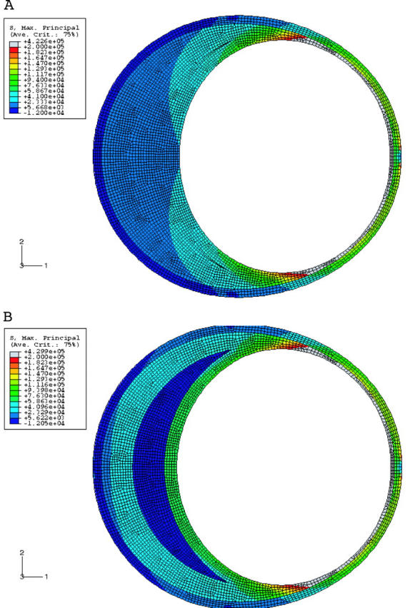
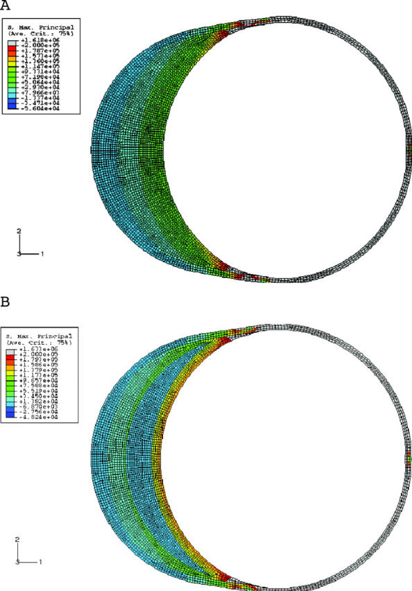
We initially looked at how shape alone, without any plaque elements, affected stress distribution inside a vessel. Figure 3 shows circles with a zoomed in view. Clearly, the haemodynamic stresses are distributed uniformly all along the circumference of the circle. What happens when this circle is changed to an ellipse of aspect ratio 1:1.25? Figure 3B shows that stresses are immediately redistributed with high stress regions concentrated along the major axis and a substantial drop in the stresses along the minor axis. As the next step, an elliptical lumen with plaque and no lipid was analysed. Figure 4A shows the results. Note that the increase in stresses towards the major axis is directly proportional to the angle from the horizontal.
Figure 3.
(A) Stress distribution in a circular lumen. Note the uniform stress distribution of the lumen. Only the top half of the figure is shown. (B) Stress distribution in an elliptical lumen. Note the higher stresses towards the major axis. Red is the highest and blue is the lowest.
Figure 4.
(A) Stress distribution for an elliptical lumen with an aspect ratio of 1.25. The vessel has plaque but no lipid. The stresses increase as the major axis is approached and are directly proportional to the angle from the horizontal. (B) As in (A) but with a lipid thickness of 400 μm at the centre. Note the higher stresses than in (A).
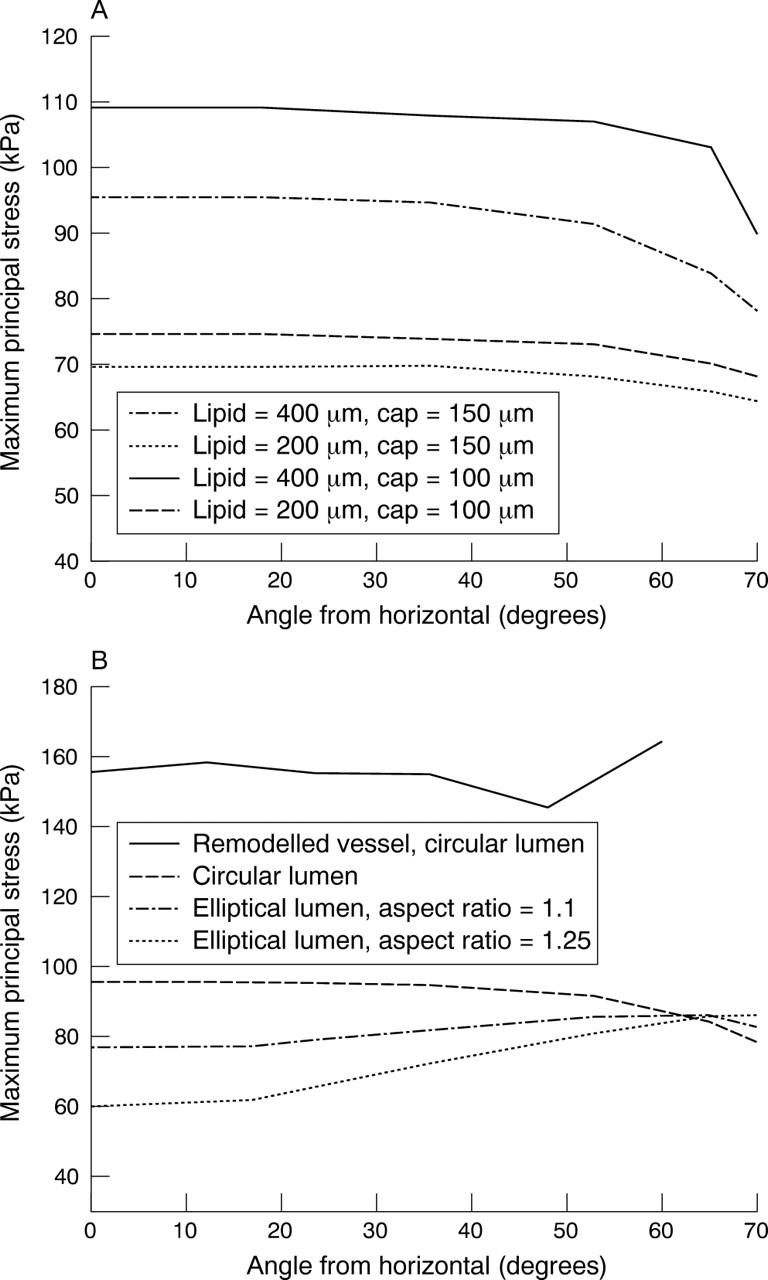
What happens when a lipid is introduced? The stresses increase proportionately to the amount of lipid (fig 4B). Figure 5 brings this out graphically. Note that stresses increase with increasing lipid and rise sharply as the major axis or shoulder area is reached. The stresses also show a very clear inverse relation with lumen stenosis and cap thickness as fig 6 shows.
Figure 5.

Stress distribution for an elliptical lumen with an aspect ratio of 1.25. The cap thickness is 150 μm and the amount of lipid is 150, 200, or 400 μm.
Figure 6.
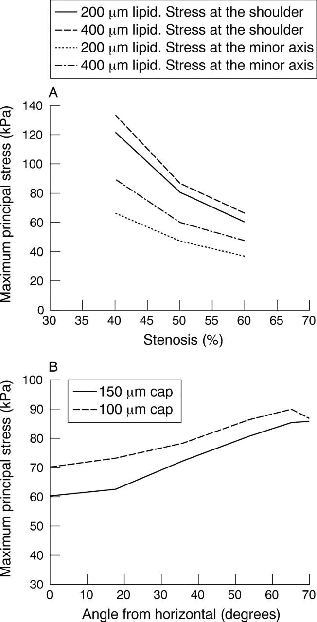
(A) Variation of stresses with percentage stenosis. Stresses were measured at the minor axis and shoulder for two lipid sizes, namely 200 and 400 μm. Ellipse 1:1.25, 150 μm cap. (B) Variation of stress with cap thickness. Elliptical lumen of 1:1.25 aspect ratio.
We then tried to answer another important question. Which is the best way to study the effect of lipid on plaque stresses? Most reported studies looked at the quantity of lipid in terms of lipid pool area.10 However, we feel that the lipid thickness at a particular location affects plaque stresses much more significantly than the overall area occupied by the lipid pool. Figures 7 and 8 bring this out. Figure 7A has no lipid present. Figure 7B is an enlarged view of the area with crescent shaped lipid and fig 7C shows the stress distribution when a very small amount of lipid (about 5% when compared with that in fig 7B) is present. As can be seen, even such a small amount at this position is enough to increase the stresses. To highlight this fact, another study was carried out in which the lipid in fig 7B was redistributed by keeping the lipid area constant and making the edges thicker and rounder than tapered. Figure 8 presents the result. The figure clearly shows that, more than the overall quantity of lipid, it is the lipid thickness at a particular location that affects plaque stresses.
Figure 7.
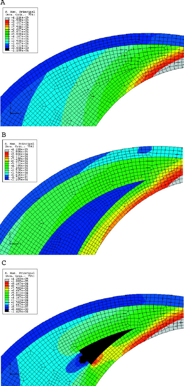
(A) Stress distribution near the shoulder region of the plaque. No lipid is present in this case. This brings out the increase in the stress near the shoulder even without the lipid. (B) Stress distribution near the shoulder region of the plaque. Lipid is crescent shaped. Note the increase in stress at the cap compared with (A). (C) Stress distribution near the shoulder region of the plaque. A small amount of lipid is introduced near the shoulder. Note the increase in stress near the shoulder. The increase is about 17% near the shoulder.
Figure 8.

Stress distribution is affected by thickness of lipid. The two cases considered in fig 7B and fig 7C have the same amount of lipid in terms of area. Compared with fig 7B, here the lipid is thicker in the shoulder region as shown in the inset. Note significantly higher stresses.
Clearly, lumen shape and the thickness of the lipid and its location have an important effect on the stress distribution in a vessel.
Shape B: circular lumen and elliptical vessel
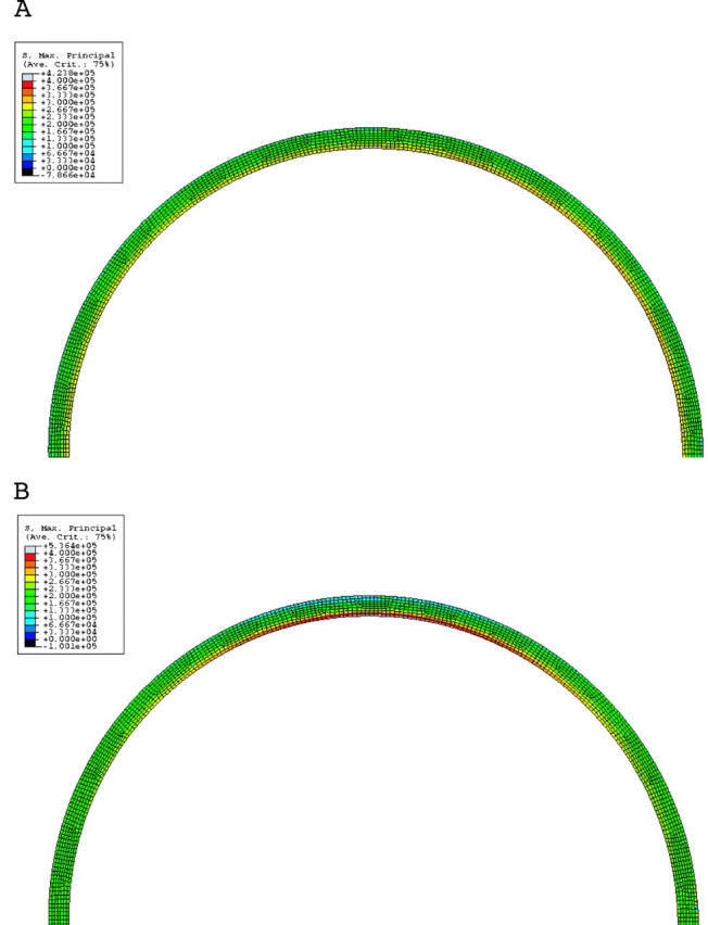
The model of shape B mimics a coronary artery with positive remodelling. Figure 9A shows the stress analysis in this condition. There is no lipid in this model. Note that the plaque size is the same as in shape A. Two important observations can be made from this figure. Firstly, the overall stresses are much higher than in shape A, by almost 100%. Secondly, the stresses also increase towards the shoulder and with increasing lipid (fig 9B and fig 10). Two factors affect the stress distribution in an outwardly remodelled vessel. The first factor is the diameter of the lumen. As the diameter is larger than in a stenotic vessel, the stresses are greater. The second factor is the plaque thickness, which decreases towards the shoulder region. Hence, the stresses are greater in this area.
Figure 9.
(A) Stress distribution in a remodelled vessel with no lipid. Note that the stresses are higher than in an elliptical lumen (fig 4A), though the plaque content is the same. (B) Same as (A) but with lipid 400 μm thick. Note that the stresses are higher than in (A) and in a corresponding condition in an elliptical lumen (fig 4B). Note the greatly increased stresses in the shoulder area.
Figure 10.

Stress distribution for a remodelled vessel showing the effect of increasing the lipid pool (200 and 400 μm). The shoulder is at an angle of 60°. Note the increase in stress at the shoulder. Cap thickness is 150 μm.
Shape C: circular lumen and circular vessel
In the condition of shape C, the amount of plaque is the same as in the first two instances. The circular shape of the lumen and vessel wall is maintained by the slightly concentric plaque, which encircles the lumen. Very clearly, fig 11 and fig 12A show that the stress distribution here is different from that in shapes A and B. The shoulder is not the region of highest stress. In fact the stresses at the summit of the lipid (0° location) are higher than at the shoulder. The effects of lipid and cap thickness on stresses are similar to those in shapes A and B, the only difference being that their impact on stresses is the same, both at the summit of the lipid and at the shoulder region. Lastly, if one were to rank the three shapes in terms of stress levels for an identical set of conditions (fig 12B), a remodelled vessel has the highest stresses, almost twice as much as the other two shapes. The difference between A and C in terms of the magnitude of maximum stress is more modest. If the lipid reaches the 90° angle in an ellipse, the stresses are similar to those in a circular lumen. If the pool of lipid is restricted to the minor axis of the ellipse, stresses in a circle are higher. The other difference is the location of peak stresses, which is at the major axis or shoulder in the case of an elliptical lumen and at the summit of the lipid in the case of the circular lumen.
Figure 11.

Principal stress distribution in a circular lumen.
Figure 12.
(A) Stress variation for a circular lumen with two different cap thicknesses and two different lipid thicknesses. (B) Comparison of stress distribution in all shapes. A remodelled vessel has the highest stresses. Thicknesses are 400 μm for the lipid and 150 μm for the cap.
DISCUSSION
Quite clearly, one of the major thrust areas of preventive cardiology is the prediction and prevention of catastrophic plaque rupture. A plaque ruptures when the biomechanical load imposed on it (estimated stress in this paper) exceeds the inherent strength of its tissues. We tried to address two important questions in this work by using finite element analysis. Firstly, why is the shoulder region of a plaque such a common site of rupture? Secondly, why are positively remodelled vessels so vulnerable to rupture?
The mechanical loads13 and inflammatory activity leading to tissue weakening are high11 in the shoulder of a plaque; thus, it is a region that can logically be expected to be a common site for plaque rupture. However, one important question that needs to be answered is, why is the shoulder region the focus of such activity?
Secondly, it is increasingly evident that positively remodelled vessels are more at risk for rupture. Increased lipid pool size and density of macrophages have been implicated in this phenomenon.5 But is that the only reason?
We attempted to answer both these questions by looking at the problem from another perspective. What is the effect of lumen shape and vessel geometry on plaque stresses? We used the well established finite element numerical model studies for these computer experiments, as parametric studies varying lumen shape and geometry in the same vessel are not easy by other experimental methods. By keeping the amount of plaque and lipid constant in all three models, we can better understand the contribution of lumen shape and vessel geometry on plaque stresses.
In an ellipse, by its very shape, even without any plaque, stresses increase as the major axis is approached as compared with a circle. The higher the aspect ratio of the ellipse, the more striking is this finding. The presence of a lipid rich plaque merely exaggerates these findings in direct proportion to the amount of lipid in the plaque. Lipid increases stresses because lipid, as a material, is very compliant. Therefore, for a given displacement, the stresses in the lipid are very low. But these lower stresses have to be compensated in other nearby regions for the overall equilibrium of the system. Therefore, increasing amounts of lipid increase stresses in the fibrous cap. Though it has been noted that the rupture in the shoulder region is predominantly due to high stresses and the stress increase is due to reduced cap thickness,16 interestingly, this work clearly brings out that the stresses increase towards the shoulder even when the cap thickness is unchanged. This increase in stresses in the shoulder region is due to two factors. One is the contribution of the elliptical lumen shape per se. The other is that, as the shoulder region is approached, the plaque becomes thinner and, due to the law of Laplace, the stresses increase. Thus, the increased vulnerability of the shoulder region clearly has a geometric basis.
However, surprisingly, the shoulder area has high stresses even for a positively remodelled vessel. In contrast, in a vessel with a circular shaped lumen (shape C), the stress distribution is dramatically different and is highest at the summit of the lipid. So, clearly, lumen shape has a profound effect on stress distribution.
The increased vulnerability of remodelled vessels is obviously due to the law of Laplace. Since normal lumen size is maintained despite a big plaque load, the stresses are very high and almost 100% more than the stresses in the other two shapes, which are more stenotic, for the same amount of lipid. This may be one of the important reasons why remodelled vessels and, for that matter mildly stenotic vessels, are more prone to rupture. In one study, over 75% of myocardial infarcts occurred in areas supplied by mildly stenosed coronary artery with less than 50% stenosis.17 These findings, however, by no means take away the importance of flow limiting, stenotic lesions in plaque vulnerability. As mentioned earlier, we have modelled only haemodynamic stresses in this study. More work is obviously needed in this area especially with regard to the effect of shear stresses and blood flow in stenotic vessels.
It should also be noted that the mechanical strength of the cap is an important factor to be considered in plaque rupture. When the stress exceeds this mechanical strength, the cap breaks. The other interesting finding in this work was the effect of lipid pool and cap thickness on plaque stresses. Though the increase in stresses with increasing lipid pool size and decreased cap thickness were in general consistent with those reported in the literature,18 there were some important new findings in this study. Significantly, in the shoulder region, where the stresses are highest in shapes A and B, the effect of lipid pool size and cap thickness is rather modest. Increased mechanical load due to the effect of geometry and tissue degradation due to biological factors such as macrophage activity may contribute as much to the vulnerability in the shoulder area as lipid size and cap thickness. This is so because the actual thickness of the lipid at the shoulder region in a crescent shaped lipid is not very different between a 200 μm and a 400 μm lipid pool size, unlike at the summit of the plaque, which is the minor axis position. In a circular lumen (shape C), however, the stresses are not only higher in the summit of the lipid but also profoundly affected by both lipid pool size and cap thickness. The other interesting finding from this study is that lipid thickness at a particular location is more important than the overall lipid pool area to regional stress distribution. The redistribution of stresses for equilibrium motioned above is largely local to the region and the presence of lipid in places of large stresses further increases the stresses in that region.
In conclusion, while it is true that actual lesions in humans are not always perfect circles or even ellipses and can have diverse shapes, and the pattern of distribution of lipid within a plaque is also not predictable and uniform, it is nevertheless clear that lumen shape, vessel geometry, and lipid location, along with its thickness, profoundly influence stress distribution in a vessel.
Acknowledgments
The authors warmly acknowledge the help of Mr K V Narasimha Rao and M Tamil Maran for their help during the investigation.
REFERENCES
- 1.Smits PC, Pasterkamp G, de Jaegere PP, et al. Angioscopic complex lesions are predominantly compensatory enlarged: an angioscopy and intracoronary ultrasound study. Cardiovasc Res 1999;41:458–64. [DOI] [PubMed] [Google Scholar]
- 2.Schoenhagen P, Ziada KM, Kapadia SR, et al. Extent and direction of arterial remodeling in stable versus unstable coronary syndromes: an intravascular ultrasound study. Circulation 2000;101:598–603. [DOI] [PubMed] [Google Scholar]
- 3.Pasterkamp G, Schoneveld AH, van der Wal AC, et al. The relation of arterial geometry to luminal narrowing and histologic markers for plaque vulnerability: the remodeling paradox. J Am Coll Cardiol 1998;32:655–62. [DOI] [PubMed] [Google Scholar]
- 4.Richardson PD, Davies MJ, Born GV. Influence of plaque configuration and stress distribution on fissuring of coronary atherosclerotic plaques. Lancet 1989;ii:941–4. [DOI] [PubMed] [Google Scholar]
- 5.Varnava AM, Mills PJ, Davies MJ. Relationship between coronary artery remodeling and plaque vulnerability. Circulation 2002;105:939–43. [DOI] [PubMed] [Google Scholar]
- 6.Pasterkamp G, Schoneveld AH, van der Wal AC, et al. Inflammation of the atherosclerotic cap and shoulder of the plaque is a common and locally observed feature in unruptured plaques of femoral and coronary arteries. Arterioscler Thromb Vasc Biol 1999;19:54–8. [DOI] [PubMed] [Google Scholar]
- 7.De Boer OJ, van der Wal AC, Teeling P, et al. Leucocyte recruitment in rupture prone regions of lipid-rich plaques: a prominent role for neovascularization? Cardiovasc Res 1999;41:443–9. [DOI] [PubMed] [Google Scholar]
- 8.Lee RT. Atherosclerotic lesion mechanics versus biology. Z Kardiol 2000;89 (suppl 2) :80–4. [DOI] [PubMed] [Google Scholar]
- 9.Humphery JD. Cardiovascular solid mechanics cells, tissues, and organs. New York: Springer-Verlag, 2002:442–5.
- 10.Berglund H, Huai L, Nishioka T, et al. Highly localized arterial remodeling in patients with coronary atherosclerosis: an intravascular ultrasound study. Circulation 1997;96:1470–6. [DOI] [PubMed] [Google Scholar]
- 11.Ogden RW. Non-linear elastic deformations. New York: Dover, 1997:488–502.
- 12.Loree HM, Grodzinsky, Park SY, et al. Static circumferential tangential modulus of human atherosclerotic tissue. J Biomech 1994;27:195–204. [DOI] [PubMed] [Google Scholar]
- 13.Hayden H, Virmani R, Younis H, et al. The impact of calcification on the biomechanical stability of atherosclerotic plaques. Circulation 2001;103:1051–6. [DOI] [PubMed] [Google Scholar]
- 14.Delfino A, Stergiopulos, Moore JE Jr, et al. Residual strain effect on the stress field in a thick wall finite element model of the human carotid bifurcation. J Biomech 1997;30:777–86. [DOI] [PubMed] [Google Scholar]
- 15.Bathe M, Kamm RD. A fluid-structure interaction finite element analysis of pulsatile flow through a compliant stenotic artery. J Biomech Eng 1999;121:361–9. [DOI] [PubMed] [Google Scholar]
- 16.Pasterkemp G, Falk E. Atherosclerotic plaque rupture: an overview. J Clin Basic Cardiol 2000;3:81–6. [Google Scholar]
- 17.Giroud D, Li JM, Urban P, et al. Relation of the site of acute myocardial infarction to the most severe coronary arterial stenosis at prior angiography. Am J Cardiol 1992;69:729–32. [DOI] [PubMed] [Google Scholar]
- 18.Loree HM, Kamm RD, Stringfellow RG, et al. Effects of fibrous cap thickness on peak circumferential stress in model atherosclerotic vessels. Circ Res 1992;71:850–8. [DOI] [PubMed] [Google Scholar]