

Abstract
We have developed a new procedure for fabricating fused silica emitters for electrospray ionization-mass spectrometry (ESI-MS) in which the end of a bare fused silica capillary is immersed into aqueous hydrofluoric acid, and water is pumped through the capillary to prevent etching of the interior. Surface tension causes the etchant to climb the capillary exterior, and the etch rate in the resulting meniscus decreases as a function of distance from the bulk solution. Etching continues until the silica touching the hydrofluoric acid reservoir is completely removed, essentially stopping the etch process. The resulting emitters have no internal taper, making them much less prone to clogging compared to e.g. pulled emitters. The high aspect ratios and extremely thin walls at the orifice facilitate very low flow rate operation; stable ESI-MS signals were obtained for model analytes from 5-μm-diameter emitters at a flow rate of 5 nL/min with a high degree of inter-emitter reproducibility. In extensive evaluation, the etched emitters were found to enable approximately four times as many LC-MS analyses of proteomic samples before failing compared with conventional pulled emitters. The fabrication procedure was also employed to taper the ends of polymer monolith-containing silica capillaries for use as ESI emitters. In contrast to previous work, the monolithic material protrudes beyond the fused silica capillaries, improving the monolith-assisted electrospray process.
INTRODUCTION
Electrospray ionization-mass spectrometry1 (ESI-MS) has become an invaluable tool for biological research due to its high sensitivity and straightforward online coupling with liquid-phase separations.2,3 A major advance in ESI-MS came with the advent of the nanospray implementation, where solution flow rates below ~50 nL/min were shown to enable additional improvements in sensitivity and quantitation.4,5 This enhanced performance is largely due to the smaller droplets generated by nanospray relative to those created at conventional flow rates (~1 μL/min).6 The smaller initial droplets are much more readily desolvated, and can result in larger MS signals despite a 30–100-fold decrease in analyte flux.6 Also, the creation of smaller droplets improves quantitation, as ion suppression and matrix effects are reduced.7 Recent work has shown that the benefits of nanospray for quantitation are even more pronounced as the flow is decreased to ultra-low rates (≤20 nL/min),8,9 where ion suppression effects can be essentially eliminated, and a trend toward equimolar response is observed.
Performance in ESI-MS is ultimately dependant upon the quality of the electrospray, which critically depends on the precise dimensions and other physical properties of the emitter, and the robustness of its performance, as well as the ability to replace emitters that fail for some reason (e.g., clogging). To produce a stable Taylor cone at nanospray flow rates, an emitter with a very small orifice is generally necessary.5 Such an emitter can be produced by heating and pulling a fused silica capillary, which causes the inner and outer diameters (i.d. and o.d., respectively) of the capillary to taper to a small aperture, typically several micrometers in diameter. While pulled emitters can successfully produce an electrospray at low flow rates, several challenges are associated with their use. First, the mechanical process of tip pulling can lead to emitters of varying quality.6 Second, because the i.d. decreases along the length of the capillary, particulate matter can become trapped10–12 and block the flow. Finally, the Taylor cone is generally supported by the emitter o.d., rather than the i.d.,10 so the thickness of the orifice walls of pulled emitters requires an even smaller i.d. for the aperture than would otherwise be required for stable operation. Hence, thick walls at the orifice can exacerbate clogging.
Chemical etching techniques have been used previously to modify the shape of fused silica capillary termini. Our group first reported removing ~1 cm of the polyimide coating from the end of a capillary and immersing the exposed portion in a hydrofluoric acid (HF) solution.13 Because HF etches silica isotropically, the resulting emitters have a constant, reduced o.d. relative to the original capillaries, a larger i.d., and a wall thickness at the orifice that depends on the etch time. Other groups have used a similar etching procedure, but flowed either water14 or gas15 through the capillaries to avoid enlarging the i.d. These approaches have been unable to produce emitters suitable for nanospray, presumably because the process of isotropically etching until the walls are very thin lacks reproducibility, and subsequent processing steps such as grinding14 and trimming16 have been reported to produce emitters with flat ends.
Other techniques have also been used to alter silica capillaries for use as ESI emitters. For example, a hybrid approach has been reported17,18 in which ESI emitters are first laser-pulled to create small apertures and then chemically etched to sharpen the orifice walls. Nanospray is facilitated, but the disadvantage of a clog-prone internal taper remains. In addition to tip pulling and chemical etching, silica ESI emitters have also been created by mechanically polishing the capillary ends to reduce the o.d.;19 such emitters effectively avoid an internal taper, but are not suitable for use at nanospray flow rates due to significant wall thicknesses at the orifice.
Recently, Oleschuk and coworkers have shown that spraying from porous monoliths inside fused silica capillaries11,12 and microchips20 can have distinct advantages over open columns, such as the ability to generate highly stable signals over a broad range of flow rates, and reduced clogging due to the presence of multiple fluid paths through the monolith. Using blunt, monolith-containing capillary ends and selecting appropriate flow rates and solvent compositions, the authors showed it was possible to generate electrospray “mists” directly from the monolith, while other experimental conditions produced a single large Taylor cone that wetted the capillary sidewalls. The “mists” most likely originated from multiple small Taylor cones that formed on the monolith surface. The use of such emitters as multielectrospray sources12, 20–22 could lead to significant enhancements in MS sensitivity.
In this work, we developed a chemical etching technique that improves the fabrication of both open tubular and monolithic silica electrospray emitters. The open tubular emitters have no internal taper, very thin walls at the orifice, and have demonstrated excellent longevity, electrospray stability, and inter-tip reproducibility. The fabrication procedure somewhat resembles a previous approach for creating fine points on optical fibers,23 generally for use as near-field optical microscopy probes.24–27 Recently, Wong, et al.28 adapted the fiber etching technique to create open needles for use as intracytoplasmic injectors by protecting the capillary interior with silicone oil. In all previous methods, etching took place at the interface between the etchant and an immiscible overlayed liquid, whereas in our procedure the taper is formed at the air-etchant interface and uses flowing water rather than silicone oil to prevent etching of the interior. The resulting emitters have larger taper angles than the etched needles and fibers previously reported, and possible contamination is avoided by exposing the emitters to water and air rather than oils and other solvents. The chemical etching procedure also enables both silica and polymer monolith-containing emitters to be produced such that the monolithic material protrudes beyond the capillary, which should facilitate monolith-assisted electrospray.
EXPERIMENTAL SECTION
Unless otherwise specified, all chemicals were purchased from Sigma-Aldrich (St. Louis, MO). Deionized water was purified using a Barnstead Nanopure Infinity system (Dubuque, IA).
Emitter fabrication
To create an ESI emitter, a ~1 cm length of polyimide coating is first burned and removed from the end of a fused silica capillary (Polymicro Technologies, Phoenix, AZ) and then a short (~1 mm) length of the bare capillary is inserted vertically into a 49% aqueous hydrofluoric acid solution (Fisher Scientific). Water is pumped through the capillary (Figure 1A) using a syringe pump (PHD 2000, Harvard Apparatus, Holliston, MA) with a 250 μL syringe (Hamilton, Reno, NV) at a flow rate of 0.1 μL/min, which prevents etchant from entering the capillary interior. Surface tension pulls a thin film of etchant up the hydrophilic capillary exterior, above the level of the bulk solution (Figure 1A). The etch rate decreases in the meniscus as a function of distance from the bulk solution (Figure 1B), and creates the taper in capillary o.d. Once the silica touching the hydrofluoric acid reservoir is completely removed (Figure 1C), the etch process is automatically halted, enabling high reproducibility between different emitters. Following etching, the capillary is removed, rinsed in water, and cut to the desired length (4–6 cm for this work) from the unetched side. To increase emitter production throughput, capillaries were etched in parallel. This was accomplished by connecting a water-containing syringe to a 7-port manifold (P-150, Upchurch Scientific, Oak Harbor, WA) via a transfer capillary. The manifold split the flow evenly between 6 transfer lines, which were each connected to individual capillaries. The capillaries were bundled together and immersed in the HF solution, and etching proceeded as for individual emitters.
Figure 1.
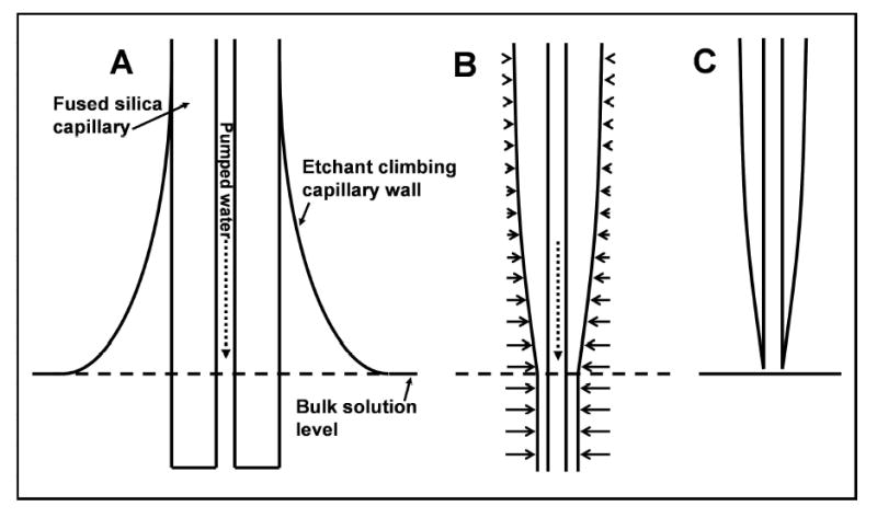
Schematic depiction of the emitter etching procedure. (A) Surface tension causes a concave meniscus to form on the capillary. (B) The etch rate in the meniscus decreases as a function of distance from the bulk solution. Horizontal arrows are vectors indicating etch rate. (C) Completed emitter after the capillary has etched through and separated from the etchant solution.
Evaluation of emitter performance
Direct infusion-based experiments to characterize ESI stability and reproducibility were performed using an MSD1100 single quadrupole mass spectrometer (Agilent Technologies, Palo Alto, CA) in which the standard ESI interface was replaced with a heated capillary-ion funnel interface.29 A syringe pump (Harvard Apparatus) with a 25-μL syringe (Hamilton) provided a controlled solution delivery rate through a transfer capillary to the silica emitters, and the ESI voltage was applied to the solution through a metal union that connected the transfer capillary to the emitters. The silica emitters were mounted on a three axis translation stage; precise positioning was achieved by adjusting the stage while looking through a stereomicroscope (Olympus SZH10, Tokyo, Japan) until the tip orifices appeared flush with the heated capillary inlet. Using the fine control of the stage, the emitters were then retracted 1.5 mm from the mass spectrometer inlet.
Robustness was evaluated by using both pulled and etched emitters with a four-column LC-MS system30 in our high-throughput proteomics laboratory31 and observing the rate of failure for the two emitter types. A variety of samples from both prokaryotic organisms and mammalian tissues and fluids were analyzed. The LC-MS system is fully automated, allowing for unattended, continuous operation. 65-cm-long, 150-lm-i.d. hand-packed LC columns with 5 lm C18 particles were used at a flow rate of approximately 1.8 lL/min. Pulled emitters were created from 200-lm-o.d., 75-lm-i.d. fused silica capillary tubing and then cut open at the end. Etched emitters were made from 150-lm-o.d., 20-lm-i.d. fused silica tubing.
Preparation of monolithic emitters
ESI emitters were also fabricated from both silica and polymer monolith-containing capillaries (50 lm i.d., 360 lm o.d.; Polymicro Technologies). The process for creating the silica monolith inside the capillary has been described in detail previously.32 Briefly, poly(ethylene glycol) (PEG; 0.88 g) and urea (0.9 g) were dissolved in 10 mL of 0.1 M acetic acid (HAc) in water. 350 μL of tetramethoxysilane was combined with 650 μL of the PEG/urea solution, and the resultant homogeneous solution was infused into pretreated fused-silica capillary tubing (Polymicro Technologies) and allowed to react at 30 °C for 20 h. The silica monolithic column was then treated with ammonia generated by the hydrolysis of the urea at 120 °C for 3 h to form mesopores. After thermal treatment of the column at 330 °C for 25 h, surface modification was carried out on-column by continuously pumping a solution of n-octadecyltriethoxysilane in toluene (10% v/v) overnight at 110 °C. As a final step, hexamethyldisilazane solution (20% in dichloromethane) was flowed through the column and reacted at 160 °C for 3 h to block unreacted silanol groups. After washing with excess toluene followed by acetonitrile, the column was cut into short lengths (~6 cm each). The procedure for removing the polyimide and chemical etching of the monolithic emitter took place as for the open tubular emitters.
A 50-cm-long poly(styrene-co-divinylbenzene) monolith-containing column was prepared by first vinylizing the inner walls of the capillary as described by Luo, et al.33 A solution containing 1 g styrene, 1 g divinylbenzene, 20 mg azobisisobutyronitrile, and 1.5 g dodecanol was prepared, sonicated for 10 min, and a small portion of the mixture was loaded into the capillary. The ends of the column were placed in a vial containing the prepolymer solution, and the column was placed in a water bath set at 60 °C for 20 h to effect polymerization. The columns was then washed with acetonitrile and cut into ~6 cm lengths. The polyimide was removed from the capillary end chemically, rather than with flame, to avoid damaging the polymer monolith: water was pumped through the capillary, and the capillary end was immersed in a 95 °C bath of Nanostrip 2X (Cyantek, Fremont, CA) for 25 min. The capillary was then rinsed in water and the end ~200 lm was placed in the HF bath as for open tubular and silica monolithic emitters. Unlike the silica monolith, the polymer monolith did not etch in the HF. Thus, rather than waiting for the emitter to completely separate from the etchant solution, the emitter was simply removed after 140 min, rinsed with water, and ready for use.
SAFETY INFORMATION
HF is extremely hazardous and corrosive. Extreme care must be taken to prevent exposure to HF liquid or vapor. HF solutions should be used in a ventilated hood, and appropriate protective equipment should be worn.
RESULTS AND DISCUSSION
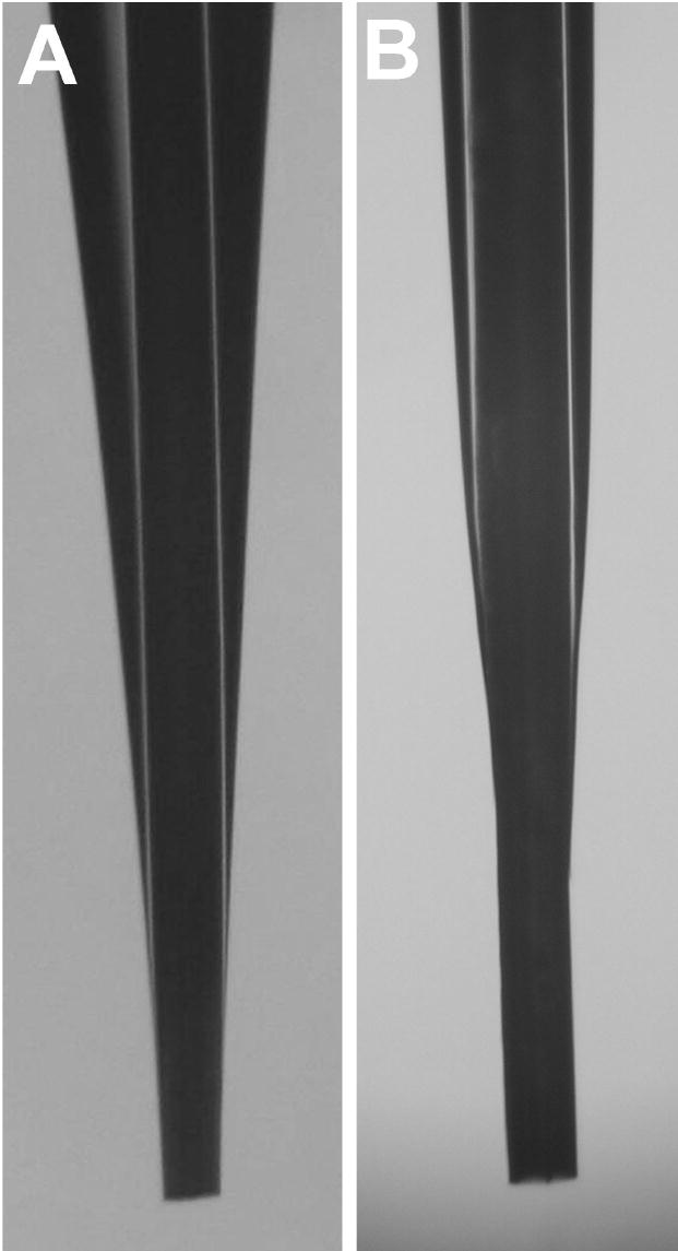
Photographs of etched open tubular ESI emitters are shown in Figure 2. Note, the 50-μm-i.d., 360-μm-o.d. capillary in Figure 2A was removed from the etchant prior to completion, and is presented to illustrate the etching process. The dashed line in this figure shows the approximate level of the bulk solution. Below the dashed line, the capillary was etched at a fixed rate, which resulted in a smaller o.d., but no angled taper. Above the dashed line, the taper in o.d. is clear. Figure 2B shows a tip that was etched to completion from a 20-μm-i.d., 200-μm-o.d. capillary. A variety of capillary dimensions that ranged from 5–50 μm i.d. and 150–360 μm o.d. were tested. This etching technique worked equally well for all capillaries tested, but thicker walls required longer etch times. 5-μm-i.d., 150-μm-o.d. capillaries required ~40 min to etch to completion. Production throughput was increased by etching up to 6 emitters in parallel, as described in the Experimental Section, and further scale up should be straightforward. In contrast to previously reported emitter etching approaches13–16 in which etching must be carefully monitored and/or timed to achieve a given wall thickness, the process reported here essentially self-terminates; etching proceeds until the tip physically separates from the liquid etchant, after which etching due to exposure to HF vapor is much slower. This etch-termination mechanism enables improved reproducibility between emitters.
Figure 2.
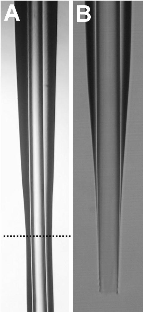
Photomicrographs of etched silica emitters. Additional description is in the text.
As discussed in the Introduction, the etching procedure reported here somewhat resembles that described for creating fine points on optical fibers23–27 and microsurgical tools.28 However, in previous applications, etching took place at the interface between the etchant and an immiscible overlayed liquid, rather than at the air-etchant interface described here. The meniscus forms due to the difference in surface tension between the two liquids, and the meniscuses are very small, leading to much shorter tapers than those observed in this work. Interestingly, the mechanism of taper formation proposed in previous work relied on a well defined interface between the two liquid phases, with the meniscus decreasing in height over time.24,27 Such a mechanism seems unlikely to be solely responsible for taper formation in this work, as a sharp interface between two liquid phases is not employed, and a dramatic decrease in meniscus height is not observed. It seems more likely that an HF concentration gradient forms in the meniscus, as etchant molecules that react with the capillary wall near the bulk solution are unavailable to react further up. Regardless of the specific mechanism, this etching procedure enables high aspect ratio tapered capillaries to be produced with desirable properties for ESI, as discussed below.
Emitter performance was evaluated in terms of MS signal stability and reproducibility. Figure 3 shows the results obtained from an analysis of reserpine in 99% water (1% HAc) at different flow rates and ESI voltages with 5-μm-i.d. emitters. 20 consecutive scans from m/z 500–1000 were used to calculate the average peak heights plotted in Figure 3. The percent relative standard deviations (RSD) shown in Figure 3 are presented as a measure of peak height variation in the 20 spectra. ESI stability was excellent; at 5 nL/min, the RSD ranged from ~7–12% for different applied voltages, and at 50 nL/min, RSD was as low as 4%. The reason that the signal intensity continues to increase with voltage at 50 nL/min but not at 5 nL/min is unclear, however it is likely the result of a switch from cone-jet mode to the less well characterized multijet mode34 at one or both flow rates as the voltage is modulated over the relatively large range. The same experiment was also carried out for reserpine in 10% methanol and 50% methanol (1% HAc, balance water in both cases). Very similar results were observed both in terms of the peak height profiles and the signal stability (data not shown).
Figure 3.
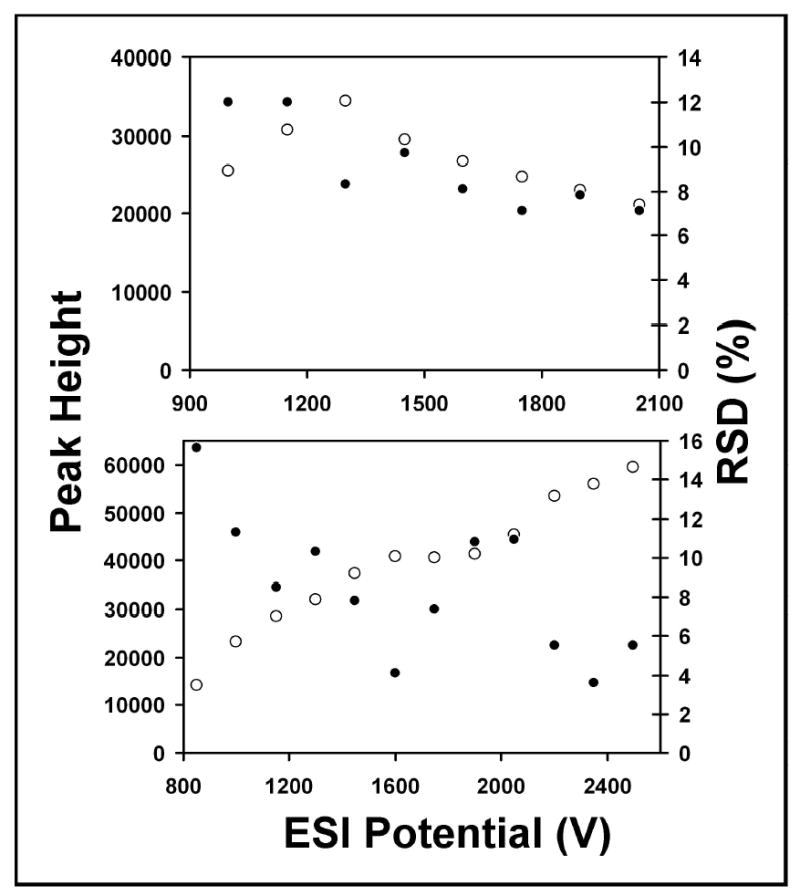
ESI performance for 5 μM reserpine at 5 nL/min (top) and 50 nL/min (bottom). Open circles refer to peak height (arbitrary units, left axes), and closed circles correspond to %RSD (right axes). The solvent was 99% water, 1% HAc.
In addition to characterizing ESI performance at different flow rates and with different solvent compositions, reproducibility between different emitters was evaluated. Figure 4 shows the reserpine peak heights for three different emitters. The RSD in Figure 4 was calculated from the peak height (the average of 20 consecutive spectra as described above) obtained from the 3 emitters at each ESI voltage. The RSD for the three emitters was 3% at 1600 V and <5% above 2300 V. This compares favorably with a similar experiment that was performed using borosilicate emitters that were created with an automated laser-based micropipette puller.35 In that study, the range of MS intensities for 7 different emitters spanned more than a factor of 2. Clearly, more precise control over emitter dimensions than that afforded by mechanical tip pulling is required to enable more quantitative, stable ESI response in the nanospray regime, and the chemical etching approach described here comes much closer to providing the desired performance.
Figure 4.
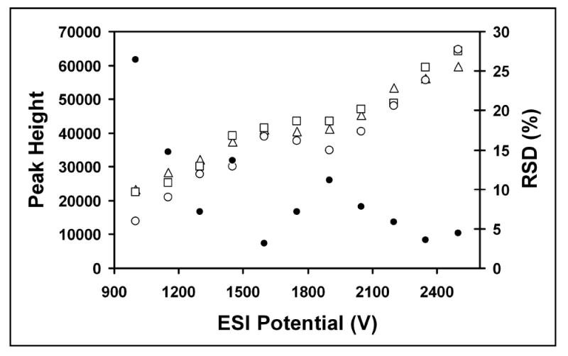
ESI-MS reproducibility for 5 μM reserpine with three 5-μm-i.d. emitters. Open shapes indicate reserpine intensity vs. ESI voltage for the different emitters (left axis). Closed circles refer to %RSD of peak height for the replicates. The flow rate was 50 nL/min and the solvent was 99% water, 1% HAc.
One of the most significant characteristics of the etched emitters is the lack of an internal taper, which was anticipated to extend lifetime by reducing clogging. We tracked the number of times pulled emitters failed on a four-column LC-MS system during a two month interval, and compared the result to the number of failures during two months after switching to the etched emitters. During the test periods, 20 pulled emitters, compared with 6 etched emitters were replaced, corresponding to an average of 18 LC-MS analyses per pulled emitter vs. 67 LC-MS analyses for each etched emitter. Instances of failure for the etched emitters were generally attributed to viscous residue from contaminated samples collecting on the emitter exteriors, or mechanical damage due to mishandling, rather than from internal clogging. We have begun utilizing the etched emitters on all of the LC-MS systems at our production proteomics facility, which has significantly reduced the risk of emitter failure and concomitant instrument down time when the automated systems are left unattended. Similarly, no clogging has been observed in our initial experience of smaller i.d. emitters (e.g., 5 lm) used for nanoLC flow.
We also employed the chemical etching approach to create emitters with silica (Figure 5A) or polymer (Figure 5B) monolithic material protruding from the capillary ends. The means of achieving monolith protrusion for the two materials differed somewhat. The silica monolith etches in the HF solution, but since water is pumped through the capillary during etching, the monolith inside and slightly beyond the capillary wall is protected. In contrast, the polymer monolith is resistant to HF, so special care must be taken that the column to be etched is not immersed very far into the etchant, or a long, fragile protruding monolith will result. When the monolith protrusion is limited to ~250 lm, as shown in Figure 5B, the polymer monolithic emitters are sufficiently robust for use, provided that mechanical damage is avoided. Also, because of the resistance of the polymer to HF, complete separation of the emitter from the etchant does not occur. Etching was timed instead. Our principal interest in monolithic emitters is for the potential development of a monolith-assisted electrospray11,12,20 as a means of enhancing ESI-MS sensitivity. However, the integration of monolithic ESI emitters with LC columns can also be used to avoid substantial post-column dead volumes associated with coupling columns to separate emitters. Previous approaches for emitter integration involved pulling36,37 or mechanically tapering38 the silica ends, which minimized36,37 or completely eliminated38 dead volume, but neither method was amenable to monolith-assisted electrospray. Oleschuk and coworkers have investigated the properties of monolith-assisted electrospray from blunt capillary ends11,12 and found that under certain ESI conditions, a single, large Taylor cone formed from the capillary o.d., while other conditions resulted in a mist emanating directly from the monolith. The protruding monolith that results with our procedure should completely eliminate the competing tendency for the solvent to wet the capillary wall, and enable further exploration of monolith-assisted electrospray with greater flexibility in terms of accessible solvent/voltage/flow rate combinations. Our preliminary results indicate a significant increase in ion currents produced with protruding monolithic emitters over a broad range of applied voltages, and we are continuing to further characterize the protruding monolith emitter properties.
Figure 5.
Photomicrographs of etched ESI emitters containing (A) silica and (B) polymer monoliths. The capillaries in both (A) and (B) were 360 lm o.d. and 50 lm i.d.
CONCLUSIONS
A new process for fabricating high aspect ratio silica ESI emitters based on chemical etching in meniscus enabled nanospray emitters to be produced that have no internal taper and are resistant to clogging. The use of 5-μm emitters at flow rates as low as 5 nL/min provided a stable nanospray in aqueous solvents (which can be problematic for ESI). The absence of mechanical processing and the effective etch-stop mechanism inherent in this fabrication technique enabled a high degree of reproducibility between different emitters. The excellent nanospray performance and the absence of a clog-prone internal taper should make these emitters valuable for ESI-MS analyses. Finally, we have shown that the etching procedure can be used to create emitters with protruding silica and polymer monolithic material, which should facilitate further characterization of monolith-assisted electrospray.
Acknowledgments
Portions of this research were supported by the U.S. Department of Energy (DOE) Office of Biological and Environmental Research and the NIH National Center for Research Resources (RR018522). Experimental portions of this research were performed in the Environmental Molecular Sciences Laboratory, a U.S. DOE national scientific user facility located at the Pacific Northwest National Laboratory (PNNL) in Richland, Washington. PNNL is a multiprogram national laboratory operated by Battelle for the DOE under Contract No. DE-AC05-76RLO 1830.
References
- 1.Fenn JB, Mann M, Meng CK, Wong SF, Whitehouse CM. Mass Spectrom Rev. 1990;9:37–70. [Google Scholar]
- 2.Smith RD, Shen Y, Tang K. Accounts Chem Res. 2004;37:269–278. doi: 10.1021/ar0301330. [DOI] [PubMed] [Google Scholar]
- 3.Simpson DC, Smith RD. Electrophoresis. 2005;26:1291–1305. doi: 10.1002/elps.200410132. [DOI] [PubMed] [Google Scholar]
- 4.Wilm MS, Mann M. Int J Mass Spectrom Ion Processes. 1994;136:167–180. [Google Scholar]
- 5.Wilm M, Mann M. Anal Chem. 1996;68:1–8. doi: 10.1021/ac9509519. [DOI] [PubMed] [Google Scholar]
- 6.Karas M, Bahr U, Dulcks T. Fresenius J Anal Chem. 2000;366:669–676. doi: 10.1007/s002160051561. [DOI] [PubMed] [Google Scholar]
- 7.Gangl ET, Annan M, Spooner N, Vouros P. Anal Chem. 2001;73:5635–5644. doi: 10.1021/ac010501i. [DOI] [PubMed] [Google Scholar]
- 8.Schmidt A, Karas M, Dulcks T. J Am Soc Mass Spectrom. 2003;14:492–500. doi: 10.1016/S1044-0305(03)00128-4. [DOI] [PubMed] [Google Scholar]
- 9.Valaskovic GA, Utley L, Lee MS, Wu JT. Rapid Commun Mass Spectrom. 2006;20:1087–1096. doi: 10.1002/rcm.2414. [DOI] [PubMed] [Google Scholar]
- 10.Cech NB, Enke CG. Mass Spectrom Rev. 2001;20:362–387. doi: 10.1002/mas.10008. [DOI] [PubMed] [Google Scholar]
- 11.Koerner T, Turck K, Brown L, Oleschuk RD. Anal Chem. 2004;76:6456–6460. doi: 10.1021/ac049438y. [DOI] [PubMed] [Google Scholar]
- 12.Lee SSH, Douma M, Koerner T, Oleschuk RD. Rapid Commun Mass Spectrom. 2005;19:2671–2680. doi: 10.1002/rcm.2109. [DOI] [PubMed] [Google Scholar]
- 13.Wahl JH, Goodlett DR, Udseth HR, Smith RD. Anal Chem. 1992;64:3194–3196. [Google Scholar]
- 14.Emmett MR, Caprioli RM. J Am Soc Mass Spectrom. 1994;5:605–613. doi: 10.1016/1044-0305(94)85001-1. [DOI] [PubMed] [Google Scholar]
- 15.Moini M, Cao P. 6,863,790. U.S. Patent. 2005
- 16.Smith RD, Severs JC. 5,993,633. U.S. Patent. 1999
- 17.Valaskovic GA, Kelleher NL, Little DP, Aaserud DJ, McLafferty FW. Anal Chem. 1995;67:3802–3805. doi: 10.1021/ac00116a030. [DOI] [PubMed] [Google Scholar]
- 18.Valaskovic GA, McLafferty FW. 5,788,166. U.S. Patent. 1998
- 19.Kriger MS, Cook KD, Ramsey RS. Anal Chem. 1995;67:385–389. doi: 10.1021/ac00098a025. [DOI] [PubMed] [Google Scholar]
- 20.Bedair MF, Oleschuk RD. Anal Chem. 2006;78:1130–1138. doi: 10.1021/ac0514570. [DOI] [PubMed] [Google Scholar]
- 21.Tang K, Lin Y, Matson DW, Kim T, Smith RD. Anal Chem. 2001;73:1658–1663. doi: 10.1021/ac001191r. [DOI] [PubMed] [Google Scholar]
- 22.Schneider BB, Douglas DJ, Chen DDY. Rapid Commun Mass Spectrom. 2002;16:1982–1990. doi: 10.1002/rcm.806. [DOI] [PubMed] [Google Scholar]
- 23.Turner DR. 4,469,554. U.S. Patent. 1984
- 24.Hoffman P, Dutoit B, Salathe RP. Ultramicroscopy. 1995;61:165–170. [Google Scholar]
- 25.Sayah A, Philipona C, Lambelet P, Pfeffer M, Marquis-Weible F. Ultramicroscopy. 1998;71:59–63. doi: 10.1364/ao.37.007289. [DOI] [PubMed] [Google Scholar]
- 26.Puygranier BAF, Dawson P. Ultramicroscopy. 2000;85:235–248. doi: 10.1016/s0304-3991(00)00069-3. [DOI] [PubMed] [Google Scholar]
- 27.Lazarev A, Fang N, Luo Q, Zhang X. Rev Sci Instrum. 2003;74:3679–3683. [Google Scholar]
- 28.Wong PK, Ulmanella U, Ho CM. J Microelectromech Syst. 2004;13:940–946. [Google Scholar]
- 29.Tang K, Page JD, Smith RD. J Am Soc Mass Spectrom. 2004;15:1416–1423. doi: 10.1016/j.jasms.2004.04.034. [DOI] [PMC free article] [PubMed] [Google Scholar]
- 30.Livesay EA, Tang K, Taylor BK, Buschbach MA, Zhao R, Shen Y, Orton DJ, Moore RJ, Udseth HR, Smith RD. Rapid Commun Mass Spectrom. 2006 submitted. [Google Scholar]
- 31. [accessed August, 2006]; http://www.emsl.pnl.gov/docs/msd/mass_spec/home/index.html.
- 32.Luo Q, Shen Y, Hixson KK, Zhao R, Yang F, Moore RJ, Mottaz HM, Smith RD. Anal Chem. 2005;77:5028–5035. doi: 10.1021/ac050454k. [DOI] [PubMed] [Google Scholar]
- 33.Luo QZ, Mutlu S, Gianchandani YB, Svec F, Frechet JMJ. Electrophoresis. 2003;24:3694–3702. doi: 10.1002/elps.200305577. [DOI] [PubMed] [Google Scholar]
- 34.Cloupeau M, Prunet-Foch B. J Electrostatics. 1990;25:165–184. [Google Scholar]
- 35.White TP, Wood TD. Anal Chem. 2003;75:3660–3665. doi: 10.1021/ac026446a. [DOI] [PubMed] [Google Scholar]
- 36.Motokawa M, Shintani Y, Miyazaki S, Suzuki K-I, Ohira M, Minakuchi H, Nakanishi K. Proceedings of the 53rd ASMS Conference on Mass Spectrometry and Allied Topics; 2005. [Google Scholar]
- 37.Xie C, Ye M, Jiang X, Jin W, Zou H. Molec Cell Prot. 2006;5:454–461. doi: 10.1074/mcp.M500272-MCP200. [DOI] [PubMed] [Google Scholar]
- 38.Luo Q, Page JS, Tang K, Smith RD. Anal Chem. 2006;78 submitted. [Google Scholar]