

Abstract
Pathologists all over the world increasingly encounter prosthetic cardiac devices. A good evaluation of these devices is a valuable source of information, which can contribute to patient care and the appreciation and understanding of the pathobiology involved in the changes occurring between the host and the implanted prosthetic device. This article summarises the considerations underlying the analysis of prosthetic devices (particularly prosthetic heart valves), including the identification of the devices, the major morphological features of the devices, their modes of failure, and some technical details about evaluation and pitfalls.
Keywords: cardiac devices, mechanical heart valves, porcine bioprosthesis, bovine pericardial prosthesis, coronary stents, aortic stents, device analysis
Prosthetic cardiac devices improve survival and greatly increase the quality of life in most patients.1 Despite considerable advances in the technology behind prosthetic devices, these devices are still far from perfect, and ongoing changes continue to be made in an effort to enhance their function, effectiveness, and life expectancy.2 Detailed evaluation of explanted devices (failed or still functional) can contribute to the future care of patients needing these devices, in addition to establishing the mechanisms of change and the pathobiology of failure of these devices. Many of these devices are still not “perfect”. In the case of new devices (new coronary and aortic stents) or modifications to devices that have been in use for some time, we suggest that the device should be referred to colleagues with the facilities and interest necessary for detailed analysis, or to the manufacturers, who will probably conduct a thorough and exhaustive analysis. Ongoing evaluation will also help to define the structural features of those devices that are most important and which are most beneficial to the host. Understanding these features may help to predict the modifications needed in the future development of these devices, in an effort to improve their safety and durability. We present a brief summary of the approach to the analysis of prosthetic cardiovascular devices, followed by a more detailed description and analysis of different devices.
“Detailed evaluation of explanted devices (failed or still functional) can contribute to the future care of patients needing these devices, in addition to establishing the mechanisms of change and the pathobiology of failure of these devices”
We will emphasise the following: (1) the objectives of evaluation, (2) the techniques of evaluation, and (3) the use of technical and other data in the necropsy/surgical pathology evaluation of prosthetic devices in individual patients.
Because prosthetic heart valves (PHVs) have been in use for a considerably longer period than most other devices, a more detailed analysis of these is presented.
Objectives of the analysis of prosthetic cardiac devices
The pathologist at the surgical pathology bench today often sees prosthetic cardiovascular devices that surgeons have explanted, or they may be seen at the time of necropsy (table 1). The detailed and complete examination of these devices can provide invaluable information. The collected information should include the following: (1) the type of device used and its manufacturer; (2) documentation of the types of changes seen in the device, such as structural deterioration, calcification, or pannus overgrowth; and (3) correlation of the morphological features in the explanted device with the clinical features, to provide a basis for an explanation of dysfunction—that is, occlusion, stenosis, or incompetence, or device failure. In any one patient, the determination of the cause of failure may contribute to subsequent management, particularly when (1) a diagnosis of infection (infective endocarditis in the case of PHVs) is made, which would necessitate a course of appropriate antibiotic treatment for the microorganism seen; (2) the presence of a thrombus is noted on a prosthetic device, which might convince the surgeon of the need to initiate immediate anticoagulant treatment.
Table 1.
Prosthetic cardiovascular devices
| Cardiac | Vascular |
| (1) Prosthetic heart valves | (1) Synthetic grafts |
| Bioprosthesis | Dacron |
| Mechanical prosthesis | PTFE |
| Bentall grafts (conduit with prosthesis) | |
| (2) Annuloplasty rings | (2) Tissue patches (pericardial) |
| (3) Synthetic sutures | (3) Synthetic patches |
| For bypass grafts | |
| For artificial chordae tendineae | (4) Vascular stents |
| (4) Pacemaker leads | (5) Endovascular devices |
| (5) Defibrillator leads | |
| (6) Tissue patches | |
| (7) Ventricular assist devices (rare) | |
| (8) Artificial hearts (rare) |
The analysis of a series of explanted devices will allow the rates and modes of failure to be defined, and the specific modes of failure of particular devices to be characterised. The clinical pathological examination and analysis of explanted devices, either new devices or modified devices, allows correlations and the compilation of data based on human experience, often far different than that obtained from the initial animal studies. The analyses also allow the biocompatibility of the host and the materials composing the device to be defined. In some instances, the establishment of timeframes of occurrence of pathological evidence of failure allows a correlation to be made with abnormalities noted on clinical investigation (such as echocardiography, computerised tomographic scan, or magnetic resonance imaging), and helps decide the time and situations in which intervention is warranted.
In addition, the observed failure modes and mechanisms help in the development of improved and new devices. Although relatively few devices are obtained before failure, when they are obtained at necropsy or at heart transplant, these devices do allow the establishment of morphological features at intermediate timeframes, before the development of overt failure. One may then speculate on the rate of progression of changes and the clinical and pathological features of devices that have functioned well, and obtain some idea of the sites where problems, such as failure modes, may arise, including the sites at which thrombus may be initiated.
“The observed failure modes and mechanisms help in the development of improved and new devices”
Knowledge of these findings can help a pathologist involved in the examination of devices from preclinical animal studies (for example, materials implanted in large animals), and can also provide expert evidence in medical legal cases related to device failure. In many, if not most, countries where devices are implanted, the state often has rules and regulations pertaining to the reporting of device related clinical problems and complications. In the USA, this is specified in the Safe Medical Devices Act of 1990 (PL101–619),3 and in Canada is mandated by the health protection branch of the Federal Ministry of Health and in the UK by the equivalent section at the Ministry of Health. In many jurisdictions, the law requires the reporting of device related deaths, serious illnesses, and injuries, by all health care personnel aware of the same, to the appropriate authorities or the manufacturers or both, depending on the nature of the incident. Any pathologist who makes this initial discovery of harm or damage relatable to a medical device malfunction should initiate this reporting process.
The reporting of findings in prosthetic cardiovascular devices necessitates some knowledge about the devices, their identifying features, and the established and potential failure modes of those devices used under particular circumstances at particular sites. Knowledge of the clinical data is usually helpful in making appropriate clinical–pathological correlations. In each situation, several generic types and many models of prosthetic devices have been used, and in some situations continue to be used.4,5 Many have long since been replaced by newer devices, which are now more widely in use. However, many pathologists will continue to encounter the “obsolete” devices. Therefore, it is essential to have some knowledge of the structure and pathology of these older devices, in addition to those that are currently implanted.
At any institution where considerable numbers of cardiovascular devices are implanted and explanted, it is worthwhile to establish a protocol for the analysis of these devices, in consultation with the physicians who implanted/explanted the device. Later analysis of these data is considerably easier when a protocol is followed, and allows better identification of complications, tissue biomaterials, and patient device interactions. The protocol should include pathological examinations such as gross and dissecting microscopic examination, specimen photography, radiology, and histological analysis (figs 1, 2). Other methods of analysis, such as embedding the devices in different synthetic materials (for example, methylmethacrylate) and electron microscopy, require equipment usually available in biomaterials research facilities or at the manufacturer’s own facilities. The principles of examination of explanted cardiovascular devices have been reported previously.2 Contemporary cardiovascular devices are numerous and a brief listing is offered in table 1. The general approach to all of these explanted devices should be the same (fig 1). The devices to be discussed in this paper will include PHVs and endovascular devices (table 1). Figure 1 shows the general protocol to be followed in the examination of explanted prosthetic cardiovascular devices. Other similar protocols are also available.4–8
Figure 1.

Gross examination of prosthetic heart devices: essential steps.
Figure 2.

Detailed examination of prosthetic heart valves. *For special investigations only. Adapted from Schoen.2 CT, computed tomography.
“At any institution where considerable numbers of cardiovascular devices are implanted and explanted, it is worthwhile to establish a protocol for the analysis of these devices”
Prosthetic heart valves
PHVs may be mechanical (MHV) (figs 3, 4, 5, 6, 7) or biological (BHV) (figs 8, 9, 10, 11).4,5,9,10 All PHVs have a passive mode of functioning, opening and closing are responses to pressure and flow changes within the heart. MHVs are made of non-physiological materials with a mobile occluder, which is usually made of fairly rigid materials. BHVs are in reality a combination of tissue and synthetic biomaterials, with the tissue itself being flexible, and today made up largely of porcine aortic valves or bovine pericardium. The appearance and functioning of tissue valves is generally similar to native heart valves. The major types of cardiac valvular replacement devices that are used fairly widely are: caged ball devices (for example, Starr-Edwards ball in cage prosthesis; fig 3); the caged disc prosthesis (for example, the Beall valve); tilting disc valves (for example, Bjork-Shiley valves; figs 4, 5); bileaflet tilting disc valves (for example, St Jude Medical valves; figs 6, 7); tissue valves (for example, Medtronic (or Hancock) porcine valves, Carpentier-Edwards (porcine or pericardial) valves; figs 8–11); and other similar devices and stentless tissue valves. Prosthetic heart valves have many complications. It is useful to be aware of these when examining a heart with a prosthetic valve in place (fig 12).
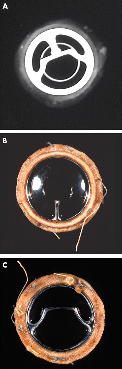
Figure 3.

(A) Anteroposterior and (B) lateral x rays of a Starr-Edwards mechanical valve (Model 1000) shows the intact “three leg cage”. (C) Flow surface and (D) non-flow surface of a “four leg cage” Starr-Edwards (Model 6400) valve. The struts are intact and the occluder (or poppet) has a pale yellow/brown colour. The non-flow surface shows tissue (arrows) still adherent to the sewing cuff.
Figure 4.

Bjork-Shiley concavo-convex valve. (A) x Ray of profile (lateral) view and (B) anteroposterior view showing the large (inflow) strut and the small (outflow) strut. Gross appearance of the valve; (C) valve partially closed with the disc in the oblique position and (D) valve open (disc or occluder is nearly vertical).
Figure 5.
(A) x Ray (anteroposterior) of a Bjork-Shiley Monostrut valve. (B) Outflow surface showing the single outflow strut and (C) inflow surface of the Bjork-Shiley monostrut valve. The struts and the disc are intact.
Figure 6.
(A–C) x Rays of a Carbomedics bileaflet valve prosthesis with the discs open, discs closed, and profile of the prosthesis, respectively; x rays also show the radio opaque prosthesis housing. (D) The flow surface (discs open) and (E) the non-flow surface of the Carbomedics bileaflet prosthesis. The flow and non-flow surfaces of the sewing cuff are carbon coated (black).
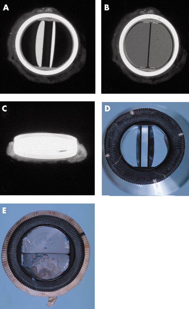
Figure 7.

(A, B) x Rays of the flow surface and profile of the St Jude Medical bileaflet prosthesis. Views of a St Jude Medical bileaflet prosthesis with (C) the leaflets open and (D) the leaflets closed. A thick layer of grey/white pannus is seen on the flow and the non-flow surfaces of the sewing ring.
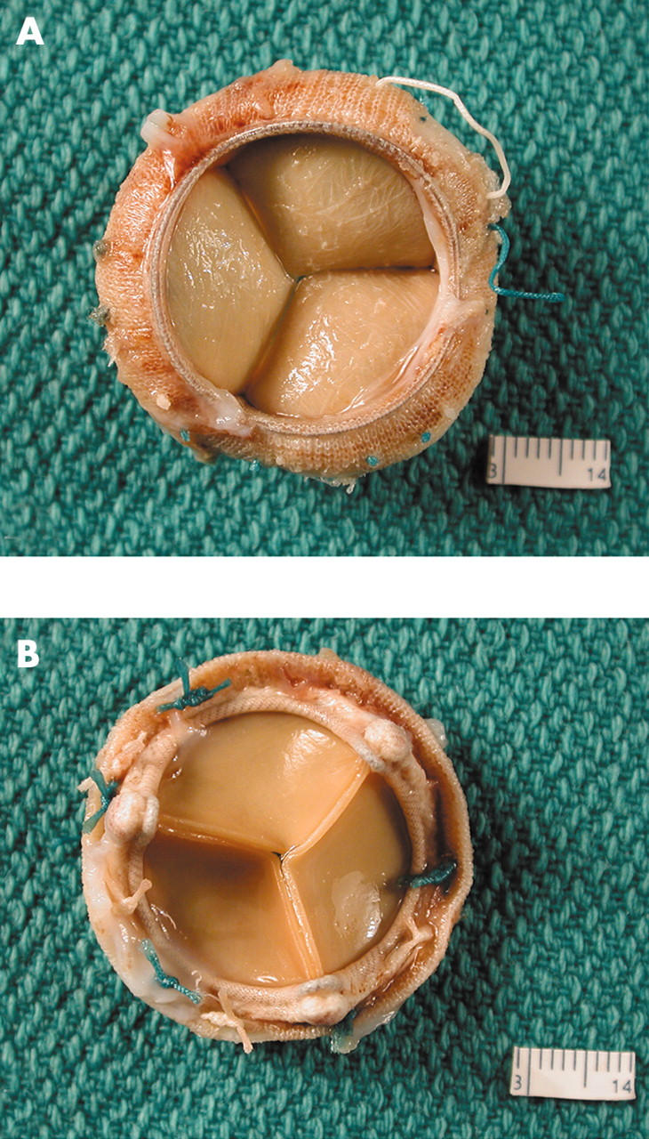
Figure 8.
(A, B) Anteroposterior and lateral x rays of a Hancock porcine valve show a radio opaque valve ring and small eyelets in each of the stent posts. (C) The flow surface and (D) the non-flow surface of the porcine valve. The cusps are soft, pliable, and intact.
Figure 9.
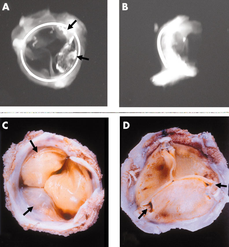
Anteroposterior and lateral x rays of an Ionescu-Shiley pericardial bioprosthesis showing the valve ring in three parts. Two of the three cusps show radio opaque areas of calcification (arrows). (C) The flow surface and (D) the non-flow views of an Ionescu-Shiley bovine pericardial valve. Pannus (arrows) is seen on the flow surface.
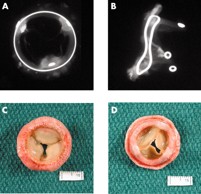
Figure 10.

Anteroposterior and lateral x rays of a Carpentier-Edwards porcine bioprosthesis. (C) The flow surface and (D) the non-flow surface of a Carpentier-Edwards porcine valve. The cusps are pliable and intact. However, all three commissural regions show detachment from the stent posts.
Figure 11.
(A) The flow surface and (B) the non-flow surface of a Carpentier-Edwards pericardial bioprosthesis. The cusps are soft, pliable, intact, and they co-apt well.
Figure 12.
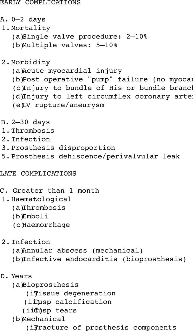
Early and late postoperative complications of prosthetic heart valves. LV, left ventricle.
MECHANICAL HEART VALVE PROSTHESES
These are prosthetic heart valves that are made entirely of synthetic materials. These devices have thrombogenic potential and patients who have these devices implanted have to be maintained on lifelong anticoagulants. These devices have three major parts, namely: (1) the occluder—this may be a ball (or poppet), a disc, or a hemidisc; (2) the superstructure, which holds the occluder in place, generally with a cage-like appearance; and (3) the valve base or housing with a fabric sewing ring.11
Although numerous MHV prostheses have been designed and used over the years, among the most widely used have been the Starr-Edwards ball in cage valve (fig 3), the Bjork-Shiley valve (figs 4, 5), the Medtronic Hall tilting disc valve, the St Jude Medical bileaflet valve (fig 7), and the CarboMedics bileaflet valve (fig 6). The ball in cage valve, among the first MHVs to be used, is still manufactured and sold in some regions of the world—although only in small numbers (Edwards Life Sciences, personal communication, 2004). However, the disc in cage valves, which had a biconvex disk, are no longer available. MHVs are constructed largely of either pure titanium (for example, the Medtronic Hall valve) or chromium cobalt alloys (for example, the Starr-Edwards and the Bjork-Shiley valves), or of graphite. The leaflets of bileaflet valves are made of graphite coated with pyrolytic carbon, which provides a smooth, strong, fatigue resistant, and highly thromboresistant surface. All PHVs have a fabric sewing ring and a stent. The sewing ring allows the surgeon to anchor the valve in place at the valve site and the valve stent or housing is for anchoring the tissue or the mechanical parts of the valve. Both cause some degree of obstruction at the valve orifice, and in many instances, this is a condition that they were meant to treat.
“Today, autografts (the patient’s own pulmonary valve), are excised and grafted into the aortic root, and a homograft placed in the pulmonary site”
Bioprosthetic heart valves (BHVs) (figs 8–11), or tissue valves (or xenografts) as they are commonly called, look very much like native aortic valves except that the implanted valve is attached to a prosthetic frame, making its commissural and infracommissural regions more rigid.6 BHVs are of two main categories: (1) heterografts or xenografts, such as porcine aortic valves or bovine pericardial valves; and (2) homografts or allografts, such as aortic or pulmonic valves primarily from human cadavers. These may both have the aortic or pulmonic arterial tissues attached to them as a conduit. Among the newest types of BHVs are autografts. In the past, these autografts were made of fascia latta or native pericardium. Today, autografts (the patient’s own pulmonary valve), are excised and grafted into the aortic root, and a homograft placed in the pulmonary site.
Xenografts are made from aldehyde preserved animal tissues, which are cleaned, sized, and mounted on a fabric covered prosthetic frame or stent.4,7,8 The preservative for these tissues is glutaraldehyde. Different manufacturers use varying strengths of glutaraldehyde. The prosthetic frame is made up of posts or struts and the intervening valve ring. Pericardial bioprostheses have also been fairly widely used and in this type of BHV the cusps are made of three pieces of glutaraldehyde treated bovine parietal pericardium. This is attached to or mounted on a frame. Detailed descriptions of these HVPs are available.4,8 Allografts are the other type of “bioprosthesis”, and are derived from cadavers or from hearts explanted for transplantation. Many of these come with the aortic root attached (root graft). Most are cryopreserved and therefore the tissue is not crosslinked; that is, it has not been treated with aldehydes. These are transplanted directly into the aortic root, without benefit of a supporting synthetic frame.
The shape of the prosthesis should be noted with special regard to the stent. Stent posts should normally be vertical. Any move away from the vertical, especially towards the orifice of the device, will probably have developed after implantation. This would lead to sagging of the bioprosthesis cusps and to dysfunction. This inward flexion or bending is known as “stent creep”, and is seen in some porcine bioprostheses, especially the older models. The presence of any surgical sutures around stent posts must be noted. Occasionally, surgical sutures meant to anchor the prosthesis to the native valve annulus get hooked over stent posts (mitral site). If this happens, at least two of the cusps become trapped or fixed in position at their commissural regions and become dysfunctional, leading to valvular incompetence, and if not corrected immediately, this leads to cusp tears and calcification. This complication should be rare today because the manufacturer supplies the BHV with sutures connecting the three stent post tips, the suture being snipped immediately after the prosthesis has been implanted in place.
Attention should be paid to the appearance of the device, especially with some idea of the normal design in mind, so that any flaws detected can be recorded. These flaws may relate to design, preimplantation or postimplantation stresses, surgical sutures, abrasion damage to biological materials adjacent to synthetic materials, and the stasis of blood—that is, thrombosis. Many of the current generation of BHVs have the cusp tissue components treated with anti-calcification (or anti-mineralisation) agents. Many techniques have been used to try and eliminate the use of glutaraldehyde as the tissue preservative. None of these has yet had commercial success. Modern porcine bioprostheses are no longer fixed under high pressure, which was meant to give the prosthesis a certain “shape” to make them more like the native valve. In these porcine valves, a backpressure of 80 mm Hg was used during the glutaraldehyde treatment, but in contrast some contemporary valves are fixed with a zero pressure gradient across the valve or stress free fixation.4 This is meant to eliminate stretching of the cusps and flattening of the cuspal connective tissue—that is, removal of the “crimp” from the porcine tissues.
Pannus
Pannus, or the host tissue reaction to devices, is usually relatively mild and occurs at the host–fabric or host–tissue interfaces. From there, this host tissue reaction, if significant, can progress on to the sewing cuff (figs 3, 7, 9) and up to the BHV interface between the biological and non-biological materials. Pannus can extend further into the biological components, leading to their stiffening and progressive stenosis and dysfunction.12–17 In MHVs, this pannus may grow over the prosthesis ring and predispose to thrombosis.5
Today, of the more than 370 000 PHVs implanted annually worldwide, just over half are mechanical, and of these, most are of the bileaflet tilting disc type, whereas approximately one third are tissue valves, with porcine aortic valve bioprosthesis being the most common (table 2). An increasing number of valves, especially mitral valves, are “repaired” (15–20%).
Table 2.
Worldwide use of prosthetic heart valves
| Prosthesis | Estimated numbers | |
| 1994* | 2003† | |
| Total | 173 900 | 370 700 |
| Mechanical | 121 000 (70%) | 192 764 (52%) |
| Ball in cage | 4900 | |
| Tilting disc | 22 000 | |
| Bileaflet | 95 200 | |
| Bioprosthesis | 52 900 (30%) | 114 917 (31%) |
| Porcine | 31 000 | |
| Pericardial | 18 700 | |
| Allograft | 3200 | |
| Native valve repair | Approximately 10–20% | |
*From Schoen2; †Medtronic Inc (valve division), personal communication, 2004.
Results of heart valve replacement
Figure 12 summarises the postoperative complications of prosthetic heart valve replacement. The mortality associated with heart valve replacement is variable and depends among others on the expertise of the surgical team, whether the procedure is being performed for the first or second time, and if it is a single or multi valve replacement. The average mortality rate ranges from 3.5% for a single valve, first time replacement to about 10% or more for a double valve or second time replacement. As the number of times the procedure is repeated or as the cross clamp (ischaemic time) time increases, so does the operative morbidity and mortality. In addition to the status of the native valve itself, the status of the myocardium is extremely important for the patient’s prognosis. A large number of early deaths are related to poor myocardial function, the result of longstanding valvular disease, and to long delays in surgery. This may be exaggerated by perioperative myocardial damage.18 In contrast, late death (30 days or more after surgery) is more often related to the prosthesis or further myocardial degeneration leading to congestive heart failure or arrhythmias. Interestingly, about 40% of patients with PHVs who die suddenly, die of valve related causes.19
Postmortem studies on explanted heart valves show a somewhat higher rate of valve related pathology than was clinically suspected. Substitute valves have relatively poor function in comparison to native valves; most have some degree of obstruction and incompetence related to the stent and the occluder. The occluder is reportedly built in to allow the surfaces to be “washed” during diastole and therefore avoid thrombosis. Up to 10 years after surgery, prosthesis associated complications are the cause of death in 50–60% of patients who have prosthetic heart valves.2,5 The overall rate at 11 years is similar for mechanical and biological prostheses.7 Common prosthesis associated complications may be classified as: (1) thrombosis, thromboembolism, and associated problems; (2) infection, annular or on the biological tissues; and (3) structural dysfunction and non-structural dysfunction.
“Interestingly, about 40% of patients with prosthetic heart valves who die suddenly, die of valve related causes”
Thrombosis is much more common in patients with MHVs than in those with BHVs. Patients who have MHVs have to be maintained on lifelong anticoagulant treatment and their coagulation status evaluated on a regular basis. Thrombosis probably starts in the low flow areas of the prosthesis, especially the hinge areas. The thrombus spreads until the occluder or hemileaflets are progressively restricted in their movement, leading to prosthesis dysfunction and increasing stenosis.20 Thrombus can form in bioprostheses also, but this is relatively rare.17 It may occasionally be seen in the smallest of the three cusps (generally posteriorly placed) of some porcine bioprosthesis.
Infection
Infection of the PHV may be annular or may involve the surface of the biological components. In MHVs, the infection generally involves the annulus and may lead to extension of thrombus over the prosthesis. Annular infection can spread and lead to further complications. In BHVs, the infection usually occurs on the tissue components, although it may also occur around the annulus. Infection of the tissues may lead to their destruction and to further prosthesis dysfunction. The rate of infection of mechanical and biological PHVs is similar.7
Dysfunction
Any of the changes listed above can lead to prosthesis dysfunction. Other reasons for prosthesis dysfunction may be host related, and these include tissue overgrowth (also known as pannus), and material degeneration. Further details about these modes of dysfunction can be found in larger reviews on bioprosthesis dysfunction.2,12,13,17 Structural dysfunction in MHVs is rare today. In the past, fractures of tilting disc valves have been reported, especially involving the Bjork-Shiley convexo–concave valves.14,21 Disc or housing fractures have been reported in the carbon components of bileaflet valves.22 Non-structural dysfunction is probably a result of an abnormal tissue–prosthesis reaction. These includes paravalvular leaks, suture failure, and suture line dehiscence.
Detailed examination of prostheses
At times, mechanical heart valve prostheses need to be examined in greater detail, usually as part of an ongoing study, or if a new prosthesis is being designed and tested in animals. In human explants, prostheses are examined further if they show evidence of premature dysfunction, disruption, or premature failure of parts of the mechanical components, such as a fracture of a hemileaflet or escape of a leaflet. This examination is best performed by dissection microscopic examination of the hinge areas and the surfaces. It may be necessary to remove all host tissues from the sewing cuff and clean the prosthesis with sodium hydroxide (10% sodium hydroxide solution). Scanning electron microscopy of fractured components may help define modes of failure.
Detailed examination of prostheses (valves or stents) may be performed for follow up studies or for the evaluation of new devices. These studies can include non-destructive examination of the device by small specimen computerised tomography, or embedding the entire device in a plastic compound (methylmethacrylate or glycol methylmethacrylate) and sectioning it with a special lathe. The thin slices so obtained are ground to provide a smooth surface and the surface stained with haematoxylin and eosin or with connective tissue stains. This process allows a much better examination of the interfaces of the tissues with the synthetic materials, and the porcine or biological tissues with the synthetic materials, in addition to examination of any host tissues with the fabric of the sewing cuff. During experimental studies, electron microscopy might be performed, and this could include transmission and scanning electron microscopy. This allows examination of the valve collagen and the assessment of its integrity.
In routine surgical or postmortem explants, these examinations are generally not warranted. In cases where the pathologist is interested, the devices can be sent back to the manufacturer for detailed analysis. The manufacturer will usually return a report on the device (an agreement to this effect must be made before sending away the device). The local evaluation must also be recorded.
Other devices
Table 1 lists the many other cardiac devices (figs 13, 14, 15, 16, 17, 18, 19). Of these, stents are the most common and are increasing rapidly in use and numbers, so that they will probably be seen more often in the future (figs 15–19).23–26 Some idea about the number of stents being used is gleaned from the fact that over $4.5 billion (US) was spent worldwide on coronary stents in 2003. The amount will probably continue to grow in the years to come. Stents may be coronary stents or those implanted in the aorta. Stents may also be “bare” or naked (no coating on the metal) or “covered” (coated with chemicals or polymers and drugs, etc to reduce/prevent tissue proliferation). Covered stents often have a fabric lining (that is, they are endografts; fig 17). Covered stents are increasingly used as aortic endografts to treat aortic aneurysms.27
Figure 13.

A Carpentier-Edwards annuloplasty ring. This D shaped ring has a hard metal core.
Figure 14.

A soft Edwards-Physio annuloplasty ring. It has a soft, synthetic core covered with synthetic fabric.
Figure 15.
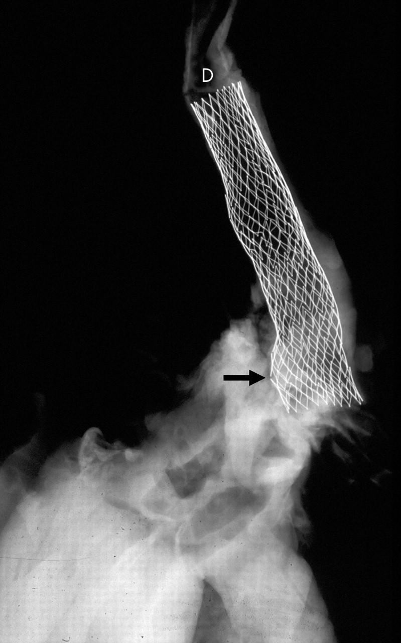
x Ray of an aortic arch and descending segment with a stent in place (D). Two of the stent struts show fractured segments (arrow).
Figure 16.
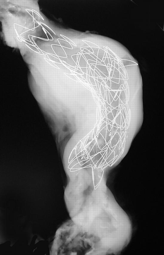
x Ray of an abdominal aorta shows a large stent in place. The most proximal segment shows an open cone (the rest of the stent is lined by fabric).
Figure 17.
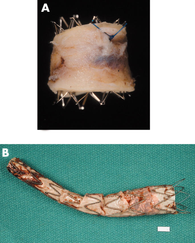
(A) An open (no fabric) stent in an aorta that had a co-arctation treated with this stent. (B) An aortic stent or endograft, showing the fabric lining the stent (on its inside (luminal) surface).
Figure 18.

A heart obtained at necropsy shows stents in a right coronary artery (arrows). The left coronary artery shows extensive calcification. A Swan-Ganz catheter is seen in the right side of the heart (right atrium, right ventricle, and pulmonary artery).
Figure 19.
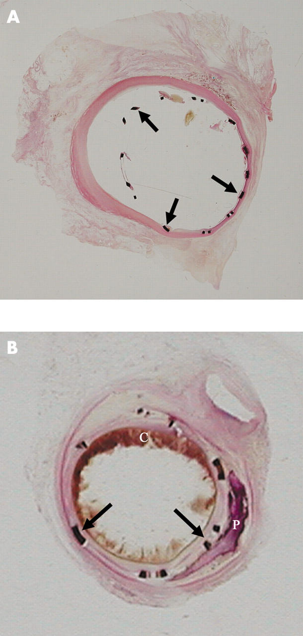
(A) Segment of coronary artery with a stent in place and embedded in GMMA, sectioned with a special lathe, surface polished, and stained with haematoxylin and eosin. This stent was in place for two weeks. The stent struts (arrows) and their relation to the vessel wall are seen. A minimal tissue reaction is seen focally. (B) This intracoronary stent was in place for seven weeks and was processed in the same manner as the stent in panel A. The stent struts are well placed and a good lumen is still evident. A circumferential tissue reaction is seen. Atherosclerotic plaque, blood clot (C), and calcification (P) are also seen.
Coronary stents
If a patient has had coronary stents implanted and the tissues available are from surgical pathology or necropsy (fig 18), these specimens should be x rayed and the exact location of the device(s) determined. A difficulty with the examination of these devices is that: (1) the native vessel is calcified, perhaps significantly so, making it difficult to visualise the device; and (2) each device is fairly small, made of metal, and is located inside the lumen of a vessel. Physical removal of the stent(s) is clearly impractical, and cutting with ordinary tools leads to ripping of the tissues, both on the outside and the inside.
Objective of examination
The primary objective in the examination of blood vessels, coronary arteries, and aortas with these devices is: (1) to exclude the possibility of rupture of the vessel wall during implantation; (2) to look for changes on the inner or flow aspect of the device, that is intima (neointima) proliferation and development of restenosis; (3) to look for changes around the stent metal to assess reaction to the metal; and (4) to look for changes in the coronary artery wall. In an effort to answer these questions, the segment of the coronary artery with the device is best embedded in plastic (methylmethacrylate) and then sectioned in the same manner as listed under PHVs. With this, transverse sections should be taken through the device at one or more points and if possible longitudinal sections from the ends, for a length of at least 5.0 mm, with a segment of native vessel attached (fig 19). The reason for making transverse sections is to assess and record the circumferential changes and the degree of luminal stenosis, and the longitudinal sections are used to assess the changes at the interface (shoulder) of the stent metal with the native vessel, because this is where there may also be pronounced tissue proliferation.
Coated stents
New devices that have come on to the market recently are stents that are coated with “anti-proliferative agents”.28,29 Some of these have a polymer coating on the device impregnated with an anti-proliferative agent (paclitaxel or sirolimus). The reaction and response to these devices in humans is not yet fully determined and detailed examination of these devices is crucial. Some adverse reactions have been reported with theses devices, highlighting the need for their critical evaluation.30–34
Aortic stents
Aortic stents are large devices, which are mounted on a balloon catheter and are deployed in the area of the aneurysm, from the arch of the aorta down to the abdominal aorta (figs 15–17).27 Although initially designed for abdominal aortic aneurysm use, they are now being used at other sites also. The device has a metal stent, usually in segments, which can be added on to each other to make the device as long as necessary for good functionality.35–38 Either the inside (usually) or the outside of the stent may have a synthetic fabric lining. In many instances, the outer aspect of this stent also has small barbs, which allow the device to be anchored to the wall of the native vessel. In addition, many stents, especially those for abdominal aneurysm use, may have a naked segment at the proximal end, so that this lies at the level of the renal (or other) arteries, without occluding them. These devices are still new and some have been voluntarily recalled by the manufacturer (see FDA website (www.fda.gov) for details). Detailed evaluation of these failed devices is obviously crucial, but is difficult and expensive. It entails the taking of tissue sections for routine tissue examination and also the examination of polymer embedded (methylmethacrylate) sections for evaluation of the stents and the tissue interfaces (fig 20). In situ radiological examinations in multiple planes are crucial, because these stents can at times migrate and therefore move away from the area meant to be treated, metal strut fracture may occur, and fractured metal components are difficult to see in a single plane x ray plate. Second, some of the metal components may fracture and lead to further complications, such as rupture of the native vessel. Infection in and around the device can occur. Blood may form a new channel around (outside) the device (an endoleak), negating the purpose of the device. Should the appropriate facilities not be available, the device should be sent to a colleague who has the appropriate facilities and the interest, or to the manufacturer, for further detailed evaluation of the explanted device.
Figure 20.

Examination of endovascular devices: stents for aortic aneurysm repair.
Take home messages.
The detailed analysis of prosthetic heart devices provides a better understanding of device tissue (or device and host) reactions
The data will allow a better understanding of the pathobiology of the changes occurring between the host and the prosthetic device
Study of the data obtained from explanted devices will help ascertain the incidence of device related complications and provide information about potential restrictions to be placed on the use of these devices
Problems with new devices (or parts of a device) can only be noted after detailed examination of used devices. Such data are crucial in deciding the future of a device
In the case of acute failures of devices such as endovascular stents, examination of the device in situ helps to define trauma to the vessel wall and its role in patient related complications
If local facilities are not available for their appropriate examination and, if warranted, the devices should be sent to colleagues who have the appropriate facilities, or even to the manufacturer, for analysis
Some of the complications associated with this device are:
(1) Difficulty in deploying the device—trauma to vessels.
(2) Occlusion of major (branch) arteries.
(3) Migration of the device after deployment.
(4) Disruption of the native vessel wall.
(5) Infection.
(6) Fracture of the metallic components of the device.
(7) The “barbs” may injure surrounding structures.
(8) Endoleak.
As shown in table 1, a large number of other devices may be explanted from the cardiovascular (and other) systems. These should be examined in a systematic manner using an acceptable protocol. All devices should be given a general evaluation. If pieces of tissue are adherent to these devices, the tissue should be sampled and submitted for histological examination.
CONCLUSION
We have presented protocols for the evaluation of prosthetic devices and a method for analysis of explanted cardiac devices. With the rapidly increasing number of artificial devices used, it is crucial to examine them fully with an accepted general protocol so that the patient or others may derive the benefit of future changes. Many devices may be seen by the practising pathologist (at surgical pathology, forensic pathology, or necropsy). If local facilities are not available for their appropriate examination and, if warranted, these should be sent to a colleague who has the interest, expertise, and facilities for their evaluation, or returned to the manufacturer for a thorough and detailed analysis. The manufacturer will usually return them with a report of the analysis of the device, along with photographs and sections, if any. Such studies and the sharing of data derived from them are the way in which these devices will continue to be improved upon and individuals in need of similar interventions will ultimately receive a perfect device.
Abbreviations
BHV, bioprosthetic heart valve
MHV, mechanical heart valve
PHV, prosthetic heart valve
REFERENCES
- 1.Rahimtoola SH. Vasodilator therapy in chronic severe aortic regurgitation. J Am Coll Cardiol 1990;16:430–2. [DOI] [PubMed] [Google Scholar]
- 2.Schoen FJ. Approach to the analysis of cardiac valve prostheses as surgical pathology or autopsy specimens. Cardiovasc Pathol 1995;4:241–55. [DOI] [PubMed] [Google Scholar]
- 3.Savage R . New law to require medical device injury reports. CAP Today 1991;40.
- 4.Butany J, Fayet C, Ahluwalia MS, et al. Biological replacement heart valves. Identification and evaluation. Cardiovasc Pathol 2003;12:119–39. [DOI] [PubMed] [Google Scholar]
- 5.Butany J, Ahluwalia MS, Munroe C, et al. Mechanical heart valve prostheses: identification and evaluation [erratum]. Cardiovasc Pathol 2003;12:322–44. [DOI] [PubMed] [Google Scholar]
- 6.Kouchoukos NT, Davila-Roman VG, Spray TL, et al. Replacement of the aortic root with a pulmonary autograft in children and young adults with aortic-valve disease. N Engl J Med 1994;330:1–6. [DOI] [PubMed] [Google Scholar]
- 7.Schoen FJ. Interventional and surgical cardiovascular pathology: clinical correlations and basic principles. Philadelphia: Saunders, 1989.
- 8.Ferraus FJ, Virmani R, Atkinson JB, et al. Cardiovascular pathology. Philadelphia: Saunders, 1991.
- 9.Jamieson WR. Modern cardiac valve devices—bioprostheses and mechanical prostheses: state of the art. J Cardiac Surg 1993;8:89–98. [DOI] [PubMed] [Google Scholar]
- 10.Morse DP, Steiner RM, Fernández J. Guide to prosthetic cardiac valves. New York: Springer-Verlag, 1985.
- 11.Silver MD, Wilson G in Silver MD. Pathology of mechanical heart valve prostheses and vascular grafts made of artificial material. In: Cardiovascular pathology. 2nd ed. New York: Churchill Livingstone, 1991:1487–1546.
- 12.Butany J, Vanlerberghe K, Silver MD. Morphologic findings and causes of failure in 24 explanted Ionescu-Shiley low-profile pericardial heart valves. Hum Pathol 1992;23:1224–33. [DOI] [PubMed] [Google Scholar]
- 13.Butany J, Yu W, Silver MD, et al. Morphologic findings in explanted Hancock II porcine bioprostheses. J Heart Valve Dis 1999;8:4–15. [PubMed] [Google Scholar]
- 14.Schoen FJ, Levy RJ, Piehler HR. Pathological considerations in replacement cardiac valves. Cardiovasc Pathol 1992;1:29–52. [DOI] [PubMed] [Google Scholar]
- 15.Roberts WC. Complications of cardiac valve replacement: characteristic abnormalities of prostheses pertaining to any or specific site. Am Heart J 1982;103:113–22. [DOI] [PubMed] [Google Scholar]
- 16.Antunes MJ. Reoperations on cardiac valves. J Heart Valve Dis 1992;1:15–28. [PubMed] [Google Scholar]
- 17.Butany J, Leask R. The failure modes of biological prosthetic heart valves. J Long Term Eff Med Implants 2001;11:115–35. [PubMed] [Google Scholar]
- 18.Schoen FJ, Titus JL, Lawrie GM. Autopsy-determined causes of death after cardiac valve replacement. JAMA 1983;249:899–902. [PubMed] [Google Scholar]
- 19.Burke AP, Farb A, Sessums L, et al. Causes of sudden cardiac death in patients with replacement valves: an autopsy study. J Heart Valve Dis 1994;3:10–16. [PubMed] [Google Scholar]
- 20.Schoen FJ, Sutton MS. Contemporary issues in the pathology of valvular heart disease. Hum Pathol 1987;18:568–76. [DOI] [PubMed] [Google Scholar]
- 21.Ericsson A, Lindblom D, Semb G, et al. Strut fracture with Bjork-Shiley 70 degrees convexo-concave valve. An international multi-institutional follow-up study. Eur J Cardiothorac Surg 1992;6:339–46. [DOI] [PubMed] [Google Scholar]
- 22.Klepetko W, Moritz A, Mlczoch J, et al. Leaflet fracture in Edwards-Duromedics bileaflet valves. J Thorac Cardiovasc Surg 1989;97:90–4. [PubMed] [Google Scholar]
- 23.O’Neill WW, Leon MB. Drug-eluting stents: costs versus clinical benefit. Circulation 2003;107:3008–11. [DOI] [PubMed] [Google Scholar]
- 24.Matsumura A, Hashimoto Y, Numano F. Influence of stent design on the immediate and long-term outcome after coronary stent implantation: a comparison of sinusoidal-ring and tube stents. Heart Vessels 2000;15:221–6. [DOI] [PubMed] [Google Scholar]
- 25.Yadav SS, Roubin GS. Coronary stenting for the treatment of abrupt or threatened closure complicating percutaneous transluminal coronary angioplasty. Coron Artery Dis 1994;5:564–70. [DOI] [PubMed] [Google Scholar]
- 26.Nair SV, McEwan JR. Angina pectoris: interventional therapies and treatment of restenosis. Int J Biochem Cell Biol 2003;35:1399–406. [DOI] [PubMed] [Google Scholar]
- 27.Dorros G, Parodi J, Schonholz C, et al. Evaluation of endovascular abdominal aortic aneurysm repair: anatomical classification, procedural success, clinical assessment, and data collection. J Endovasc Surg 1997;4:203–25. [DOI] [PubMed] [Google Scholar]
- 28.Moussa I, Leon MB, Baim DS, et al. Impact of sirolimus-eluting stents on outcome in diabetic patients: a SIRIUS (SIRolImUS-coated Bx Velocity balloon-expandable stent in the treatment of patients with de novo coronary artery lesions) substudy. Circulation 2004;109:2273–8. [DOI] [PubMed] [Google Scholar]
- 29.Chieffo A, Colombo A. Polymer-based paclitaxel-eluting coronary stents. Clinical results in de novo lesions. Herz 2004;29:147–51. [DOI] [PubMed] [Google Scholar]
- 30.Kereiaks DJ, Choo JK, Young JJ. Thrombosis and drug-eluting stents: a critical appraisal. Rev Cardiovasc Med 2004;5:9–15. [PubMed] [Google Scholar]
- 31.Chong PH, Cheng JW. Early experiences and clinical implications of drug-eluting stents: part 1. Ann Pharmacother 2004;38:661–9. [DOI] [PubMed] [Google Scholar]
- 32.Chong PH, Cheng JW. Early experiences and clinical implications of restenosis and drug-eluting stents: Part 2. Ann Pharmacother 2004;38:845–52. [DOI] [PubMed] [Google Scholar]
- 33.Diller R, Senninger N, Kautz G, et al. Stent migration necessitating surgical intervention. Surg Endosc 2003;17:1803–7. [DOI] [PubMed] [Google Scholar]
- 34.Moses JW, Kipshidze N, Leon MB. Perspectives of drug-eluting stents: the next revolution. Am J Cardiovasc Drugs 2002;2:163–72. [DOI] [PubMed] [Google Scholar]
- 35.Chuter TA. The choice of stent-graft for endovascular repair of abdominal aortic aneurysm. J Cardiovasc Surg (Torino) 2003;44:519–25. [PubMed] [Google Scholar]
- 36.Varma C, Benson LN, Butany J, et al. Aortic dissection after stent dilatation for coarctation of the aorta: a case report and literature review. Catheter Cardiovasc Interv 2003;59:528–35. [DOI] [PubMed] [Google Scholar]
- 37.Nienaber CA, Eagle KA. Aortic dissection: new frontiers in diagnosis and management. Part I: from etiology to diagnostic strategies. Circulation 2003;108:628–35. [DOI] [PubMed] [Google Scholar]
- 38.Nienaber CA, Eagle KA. Aortic dissection: new frontiers in diagnosis and management. Part II: therapeutic management and follow-up. Circulation 2003;108:772–8. [DOI] [PubMed] [Google Scholar]