Abstract
A stiff skin forms on surface areas of a flat polydimethylsiloxane (PDMS) upon exposure to focused ion beam (FIB) leading to ordered surface wrinkles. By controlling the FIB fluence and area of exposure of the PDMS, one can create a variety of patterns in the wavelengths in the micrometer to submicrometer range, from simple one-dimensional wrinkles to peculiar and complex hierarchical nested wrinkles. Examination of the chemical composition of the exposed PDMS reveals that the stiff skin resembles amorphous silica. Moreover, upon formation, the stiff skin tends to expand in the direction perpendicular to the direction of ion beam irradiation. The consequent mismatch strain between the stiff skin and the PDMS substrate buckles the skin, forming the wrinkle patterns. The induced strains in the stiff skin are estimated by measuring the surface length in the buckled state. Estimates of the thickness and stiffness of the stiffened surface layer are estimated by using the theory for buckled films on compliant substrates. The method provides an effective and inexpensive technique to create wrinkled hard skin patterns on surfaces of polymers for various applications.
Keywords: focused ion beam surface modification, polydimethylsiloxane, surface wrinkles
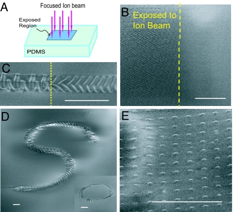
Wrinkle patterns shown in Fig. 1 are formed by exposing the surface area of a flat polydimethylsiloxane (PDMS) sheet (thickness ≈3 mm, Young modulus ≈2 MPa) (1) to a focused ion beam (FIB) of Ga+ ions as shown schematically in Fig. 1A. This method can create wrinkle patterns of various widths and complexity by controlling the relative motion of the polymeric substrate and the FIB to scan selected areas as shown in Fig. 1 B–E. The wrinkles appear only on the areas of the PDMS exposed to FIB (see Fig. 1 B and C), due to buckling of the stiff skin formed on the areas of the PDMS exposed to FIB. FIB exposure creates a tendency for the skin to expand in the direction perpendicular to the direction of FIB irradiation if it was not constrained by the PDMS substrate, similar to the effect observed in exposing metallic surfaces to ion beam irradiation (2–4). The mismatch strain between the stiff skin and its substrate give rise to skin buckling and the formation of the wrinkle patterns (5–9). FIB exposure differs from UV/ozone treatment of PDMS in that the latter produces a stiff skin by increasing cross-links with relatively little strain mismatch (10, 11). The morphology of the wrinkle patterns on the surface areas of PDMS is mainly a function of ion fluence as shown in Figs. 1C and 2. Fig. 1D shows that the path of the wrinkle patterns can be selected by controlling the relative motion of the substrate and ion beam. In addition, one can create islands of buckled stiff skins on the PDMS by controlling the ion beam spot diameter and spacing (see Fig. 1E).
Fig. 1.
Wrinkle patterns on PDMS surface induced by FIB irradiation. (A) Selected surface areas of the PDMS are exposed to FIB as shown schematically. (B) The wrinkles appear only on the areas of the PDMS exposed to FIB. The SEM picture shows the boundary of a 200 × 200-μm region exposed to FIB with the fluence of ≈1013 ions per cm2 in a single scan mode. The wrinkles on the exposed area are 1D with the wavelength of ≈460 nm, while the unexposed surface remains flat. (C) The morphology of the wrinkled skin depends on the ion fluence, which can be controlled by varying the relative velocity of the substrate and the beam. The SEM image shows a wrinkled pattern generated along a straight path with width of 4.0 μm with two different ion fluences: 1.8 × 10¹⁴ (Right) and 9 × 10¹⁵ (Left) ions per cm2. The surface of the PDMS outside this path remains flat. (D) The wrinkle pattern can be generated along selected paths with specified width by controlling the relative motion of the substrate and ion beam. Here the pattern follows an S-shaped path with a width of 6 μm, created at a constant ion fluence, 5.0 × 10¹⁵ ions per cm2. Inset shows a circular path with the same width created at the same ion fluence. (E) Islands of buckled stiff skins on the PDMS created by controlling the ion beam spot diameter and ion beam spot spacing. Each island has the diameter of ≈500 nm and is a smooth buckle with peak height of ≈35 nm. The spacing between the islands is ≈1.5 μm. The applied ion fluence (averaged over the whole area of the PDMS) is 7 × 10¹² ions per cm2. (Scale bars: 10 μm.)
Fig. 2.
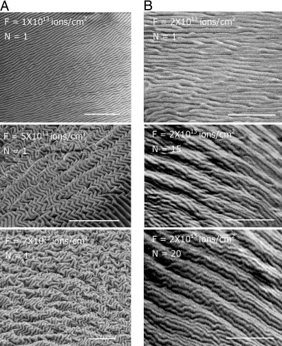
The surface morphology of the wrinkle patterns induced by FIB depends primarily on the applied ion fluence. (A) SEM images of the surface morphology of the PDMS exposed to FIB in a single scan mode (N = 1) with various ion beam fluences, F (ions per cm2). (B) SEM images of the surface morphology created by N scans each with fluence, F = 2.0 × 10¹³ ions per cm2. (Top) SEM image shows the surface morphology after the first scan. AFM examination of the surface shows that the surface has a wavelength of ≈470 nm. (Middle and Bottom) SEM images of the surface after N = 15 (Middle) and 20 (Bottom) scans (with accumulated fluence, N × F, of 3.0 × 10¹⁴ and 4.0 × 10¹⁴ ions per cm2, respectively) reveals complex patterns of the surface with a hierarchical nature. (Scale bars: 10 μm.)
Various morphologies shown in Fig. 2A are created by a single mode FIB scanning with the beam current of 1 nA and the fluences indicated. When the PDMS substrate is exposed with a fluence on the order of 1 × 10¹³ ions per cm2, the wrinkles are mainly straight and one-dimensional (1D) with an average wavelength of ≈460 nm. Herringbone wrinkles form at a fluence of 5 × 10¹³ ions per cm2. Nested hierarchical patterns are created at a fluence of ≈7 × 10¹³ ions per cm2 or greater, with primary wrinkles having average wavelength of ≈460 nm nested in the larger secondary wrinkles with average wavelength ≈2.0 μm, revealing the hierarchical nature of wrinkling structures. Another simple method for controlling the applied fluence and consequently the morphology of the wrinkles is multiple scanning of the same region by an FIB with constant beam current, as shown in Fig. 2B, here with N denoting the number of scans and F as the fluence per scan.
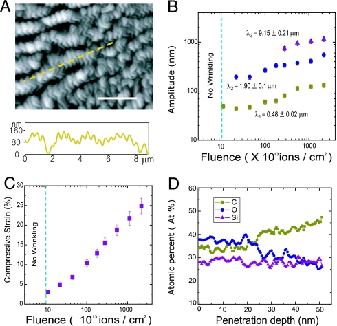
To quantify the morphology of the wrinkle patterns, we examined the topology of the wrinkles by using atomic force microscopy (AFM) in the tapping mode (Fig. 3A). For the fluences of ≈1 × 10¹³ ions per cm2, a periodic, 1D profile appears on the regions exposed to FIB, whereas at fluences below this level the surface of the PDMS remains flat (Fig. 3 B and C). By increasing the fluence, the amplitude of the wrinkles increases as shown in Fig. 3B. At the fluence of ≈2 × 10¹³ ions per cm2, a second generation of wrinkles appears with average wavelength of ≈1.95 μm. Examination of the morphology of the patterns created at fluences >3 × 10¹⁴ ions per cm2 reveals the existence of a third generation of the wrinkles with average wavelength of ≈8.65 μm. We estimated the average induced strain in the stiff skin as a function of FIB fluence from the measured lengths along the surface of the wrinkle patterns (Fig. 3C; see Materials and Methods). The strain in the stiff skin is estimated to be 3.1% at FIB fluence of 1013 ions per cm2, which is the lowest fluence leading to appearance of wrinkles. The strain increases approximately linearly with the logarithm of the fluence.
Fig. 3.
Examination of the surface topology and chemical composition of the PDMS exposed to FIB through depth. (A) (Upper) Morphology of PDMS surface exposed to FIB with fluence of 5.0 × 10¹³ ions per cm2 obtained by using AFM. (Scale bar: 3 μm.) (Lower) The normal deflection of the surface along the path identified in Upper by the dashed line. (B) Amplitude of the hierarchical wrinkles formed upon exposure of the PDMS surface to FIB with various fleunces. The primary wrinkles appear at the fluence of ≈1013 ions per cm2. The characteristic wavelengths associated with the surface morphology are calculated by FFT of the surface undulations obtained by AFM. (C) Average compressive strain in the stiff skin formed by exposure of the PDMS surface area as a function of ion fluence. The compressive strain is calculated by averaging the strain along at least five directions for each morphology studied (see Materials and Methods). (D) AES analysis of the PDMS surface exposed to FIB with ion fluence of 1.1 × 10¹³ ions per cm2. Because of exposure to the FIB, the concentration of C and O were changed at the first 25 nm of the PDMS from that of the original PDMS, whereas the Si component remains almost constant through the depth. Atomic concentrations of Si, O, and C become close to the pure PDMS after depth of 25 nm from the surface with average ratio of O/Si atomic concentration ≈0.97.
The critical strain associated with buckling of a uniform stiff elastic skin attached to a compliant elastic substrate, εc, is approximately (5, 12–14):
where Es and Ef are the elastic moduli of the substrate and stiff skin, respectively. Furthermore, the wavelength of the primary wrinkles, λ1, of a stiff skin with thickness t is approximately:
Substitution of εc = 0.031 and λ1 = 460 nm from the experimental measurements leads to estimates of the thickness and stiffness of the skin: t ≈ 28 nm, Ef/Es ≈ 70. The estimated skin thickness is ≈5 times larger than the thickness of the skin reported on PDMS samples subject to UV/ozone treatment, whereas the stiffness is comparable (10, 11, 15).
As a final step, the chemical composition of exposed areas of the PDMS was examined through depth by using Auger electron spectroscopy (AES) (see Materials and Methods). The results of AES analysis for the PDMS exposed to ion fluence of 1.1 × 10¹³ ions per cm2 is shown in Fig. 3D. Atomic concentration ratio of O/Si has the average value of 1.37 in the first 25 nm of the depth profile, whereas the atomic concentration of C is lower than that of the pure PDMS. This suggests that the thin skin, formed on the polymer surface upon exposure to FIB, has a chemical composition similar to SiOx. A similar observation is reported for the stiff skin appearing on PDMS substrate exposed to Ar+ ion beam (16). The thickness of this stiff skin is ≈25 nm, which is in agreement with the predicted value of 28 nm from the simple theory presented above. We also used energy dispersive spectroscopy (EDS) built into the FIB/SEM system to examine the chemical composition of exposed areas of the PDMS exposed to FIB with various ion fluences, which led to similar observations.
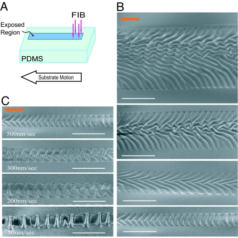
In Fig. 4, another simple method of creating wrinkled, hard skins on selected regions of the PDMS is demonstrated by using FIB irradiation. Here, the PDMS substrate is moved at a constant speed relative to the FIB (Fig. 4A). The wrinkle patterns shown in Fig. 4B are formed by moving the PDMS at a constant speed of 500 nm/s, while the FIB fluence is controlled by decreasing the width of the exposed area from 50 to 4 μm at a constant beam current of 1 pA. In Fig. 4C, the morphology of the wrinkles is controlled by varying the speed of the PDMS substrate, while maintaining the width of the exposed area constant at 4 μm. This leads to the fluence ranging from 50 to 4 μm. The path of the wrinkle patterns can be selected simply by controlling the relative motion of the substrate and ion beam as shown in Fig. 1D, and the morphology of the surface can be changed by controlling the ion fluence as in Fig. 1C. This method allows the formation of paths of rough wrinkles on the surface of the PDMS that might be useful in developing multifunctional microfluidic devices (17, 18).
Fig. 4.
Various morphologies of the wrinkled skins induced by controlling the relative motion of the ion beam and PDMS. (A) By moving the PDMS stage during the FIB irradiation, long channel patterns can be produced. (B) SEM images of the regions of the PDMS exposed to FIB showing various surface morphologies created by changing the width from 20 μm (top image) to 4 μm (bottom image). The PDMS stage has a constant velocity of 500 nm/s and the beam current is 1 pA. The ion fluence varies from 7.2 × 10¹³ to 1.8 × 10¹⁵ ions per cm2 (top to bottom images). (C) Surface morphologies created by varying the moving speed of the PDMS stage from 50 to 500 nm/s, while the width of the exposed area is kept constant as 4 μm. The beam current is constant at 1 pA such that the fluence varies from 1.8 × 10¹⁵ to 1.8 × 10¹⁶ ions per cm2. Note that the overall shape of the patterns also can be controlled as shown in Fig. 1D. (Scale bars: 10 μm.)
Conclusions
In conclusion, methods to create patterns of wrinkled stiff skin on a polymeric substrate upon exposure to FIB have been demonstrated and characterized. FIB irradiation alters the chemical composition of the polymer close to its surface and induces a thin stiff skin with a strain mismatch. Wrinkle patterns can be generated along selected paths with specified widths by controlling the relative movement of the ion beam and polymeric substrate, while wavelengths and amplitudes of wrinkles can be achieved in the micrometer and submicrometer level by varying the ion beam fluence. The method is simple and inexpensive. The surface patterns have potential for technological applications such as building biological sensors (19–21), controlled patterning of polymer surfaces for optical diffraction gratings (22), and developing multifunctional fluidic devices at the micrometer and submicrometer level.
Materials and Methods
Material Preparation.
PDMS networks were prepared by mixture of elastomer and cross-linker in mass ratio of 15:1 (Sylgard-184; Dow Corning, Midland, MI). The mixture was placed in a plastic box and stirred to remove trapped air bubbles and then cured at 80°C for 60 min, resulting in cross-linked PDMS network. PDMS coupons of dimension 20 × 20 × 0.3 mm were cut for the experiments.
FIB Irradiation.
A FESEM/FIB dual-beam system (FE-SEM/FIB Dual Beam NOVA; FEI, Hillsboro, OR) was used for FIB irradiation and SEM imaging. PDMS coupons were placed in the high vacuum chamber under the working pressure of ≈5 × 10⁻⁵ Pa. The PDMS surface was exposed to focused Ga+ ion beam in a digital mode with the acceleration voltage of 30 keV and ion current in the range of 1 pA to 10 nA. The incident angle between the Ga+ ion beam and the PDMS target surface and beam dwell time were kept at 90° and 3 μs in all of the experiments, respectively. The SEM images in the exposed region were taken by a built-in secondary electron microscopy.
Measurement of Wrinkle Patterns Topology.
The surface topology of the wrinkle patterns induced by FIB was examined by using AFM (Nanoscope III; Digital Instruments, Round Lake, NY) in the tapping mode. The strain in the stiff skin induced by FIB irradiation was estimated by direct measurement of the surface length along a measurement line (L) and the straight-line distance between its two ends (L0) from the profiles obtained by using AFM (see, for example, Fig. 3A). The induced strain along the line is taken as the approximation (L − L0)/L0.
Chemical Composition Analysis.
The chemical composition of the region of the PDMS exposed to FIB (specifically, the concentration of three major chemical components of the PDMS, O, Si, and C) was examined by using AES (PerkinElmer 660; PerkinElmer, Wellesley, MA) with 2-keV electron beam and depth resolution of <2 nm. Depth profile for the chemical components was obtained by using controlled sputtering rate of 5.1 nm/min, calibrated by comparison with the sputtering rate of SiO2 (23).
Acknowledgments
We thank Dr. M. Aziz and Dr. L. Mahadevan for fruitful discussions. This work was supported in part by Korea Research Foundation Grant M01-2005-000-10198-0 (to M-W.M.), the Center for Advanced Materials Processing (CAMP) of the 21st Century Frontier R&D Program (K.H.O.), by Office of Naval Research Grant N00014-04-1-0154 (to M-W.M. and J.W.H.), and the Division of Engineering and Applied Sciences, Harvard University (A.V. and J.W.H.).
Abbreviations
- PDMS
polydimethylsiloxane
- FIB
focused ion beam
- AFM
atomic force microscopy
- AES
Auger electron spectroscopy.
Footnotes
The authors declare no conflict of interest.
References
- 1.Wilder EA, Guo S, Lin-Gibson S, Fasolka MJ, Stafford CM. Macromolecules. 2006;39:4138–4143. [Google Scholar]
- 2.Klaumunzer S, Schumacher G. Phys Rev Lett. 1983;51:1987–1990. [Google Scholar]
- 3.Kim YR, Chen P, Aziz MJ, Branton D, Vlassak JJ. J Appl Phys. 2006;100:104322. doi: 10.1063/1.2363900. [DOI] [PMC free article] [PubMed] [Google Scholar]
- 4.Otani K, Chen X, Hutchinson JW, Chervinsky JF, Aziz MJ. J Appl Phys. 2006;100 023535. [Google Scholar]
- 5.Bowden N, Brittain S, Evans AG, Hutchinson JW, Whitesides GM. Nature. 1998;393:146–149. [Google Scholar]
- 6.Cerda E, Mahadevan L. Nature. 2003;419:579–580. doi: 10.1038/419579b. [DOI] [PubMed] [Google Scholar]
- 7.Genzer J, Groenewold J. Soft Matter. 2006;2:310–323. doi: 10.1039/b516741h. [DOI] [PubMed] [Google Scholar]
- 8.Lacour SP, Wagner S, Huang Z, Suo Z. Appl Phys Lett. 2003;82:2404–2406. [Google Scholar]
- 9.Yoo PJ, Suh KY, Park SY, Lee HH. Adv Mater. 2002;14:1383–1387. [Google Scholar]
- 10.Ouyang M, Yuan C, Muisener RJ, Boulares A, Koberstein JT. Chem Mater. 2000;12:1591–1596. [Google Scholar]
- 11.Efimenko K, Rackaitis M, Manias E, Vaziri A, Mahadevan L, Genzer J. Nat Mater. 2005;4:1–5. doi: 10.1038/nmat1342. [DOI] [PubMed] [Google Scholar]
- 12.Cerda E, Mahadevan L. Phys Rev Lett. 2003;90 doi: 10.1103/PhysRevLett.90.074302. 074302. [DOI] [PubMed] [Google Scholar]
- 13.Huang ZY, Hong W, Suo Z. Phys Rev E. 2004;70 doi: 10.1103/PhysRevE.70.030601. 030601(R) [DOI] [PubMed] [Google Scholar]
- 14.Chen X, Hutchinson JW. ASME J Appl Mech. 2004;71:597–603. [Google Scholar]
- 15.Efimenko K, Wallace WE, Genzer J. J Colloid Interf Sci. 2002;254:306–315. doi: 10.1006/jcis.2002.8594. [DOI] [PubMed] [Google Scholar]
- 16.Satriano C, Conte E, Marletta G. Langmuir. 2001;17:2243–2250. [Google Scholar]
- 17.Stone HA, Stroock AD, Ajdari A. Annu Rev Fluid Mech. 2004;36:381–411. [Google Scholar]
- 18.El-Ali J, Sorger PK, Jensen KF. Nature. 2006;442:403–411. doi: 10.1038/nature05063. [DOI] [PubMed] [Google Scholar]
- 19.Hynes RO, Lander AD. Cell. 1992;68:303–322. doi: 10.1016/0092-8674(92)90472-o. [DOI] [PubMed] [Google Scholar]
- 20.Kim SR, Teixeira AI, Nealey PF, Wendt AE, Abbott NL. Adv Mater. 2002;14:1468–1472. [Google Scholar]
- 21.Khademhosseini A, Langer R, Borenstein J, Vacanti J. Proc Natl Acad Sci USA. 2006;103:2480–2487. doi: 10.1073/pnas.0507681102. [DOI] [PMC free article] [PubMed] [Google Scholar]
- 22.Harrison C, Stafford CM, Zhang W, Karim A. Appl Phys Lett. 2004;85:4016–4018. [Google Scholar]
- 23.Hofmann S. Appl Phys. 1976;9:59–66. [Google Scholar]


