

Abstract
We report on a new electrodynamic ion funnel that operates at a pressure of 30 Torr with no loss of ion transmission. The enhanced performance compared to previous ion funnel designs optimized for pressures of <5 Torr was achieved by reducing the ion funnel capacitance and increasing the RF drive frequency (1.7 MHz) and amplitude (100-170 V peak-to-peak). No degradation of ion transmission was observed for pressures from 2 - 30 Torr. The ability to operate at higher pressure enabled a new tandem ion funnel mass spectrometer (MS) interface design that can accommodate a greater gas load. When combined with a multicapillary inlet, the interface provided more efficient introduction of ions, resulting in a significant enhancement in MS sensitivity and detection limits.
Introduction
A higher efficiency electrospray ionization/mass spectrometry (ESI-MS) interface has the potential to provide both increased sensitivity and lower detection limits, which in turn can decrease sample size requirements, increase analytical throughput and enable new biological applications [1-3]. While ESI sensitivity can be increased by electrospraying at lower flow rates (i.e., nanoelectrospray [4]), this approach is ultimately limited by the flow rate at which ESI efficiency reaches 100% (generally in the low nL/min regime) [2] and the fact that on-line separations (e.g. using liquid chromatography; LC) typically operate at much greater flow rates. Additionally, all else being equal, the total ESI current actually decreases as flow rate is decreased [5]. A key factor that limits overall ion utilization is the efficiency of ion transport from atmospheric pressure to the first differentially pumped region (typically operating at a pressure of 1-3 Torr). In this region, a “skimmer cone” or other sampling aperture functions as a conductance limit that allows a small fraction of the ions (and gas) that enter to be transported to the low pressure regions of the MS analyzer.
Over the last 15 years significant effort has been focused on optimizing the efficiency of ion transmission from the ESI emitter into the MS and into the lower pressure regions of the mass spectrometer [6-14]. These efforts have resulted in significant gains in sensitivity, but design optimization efforts have generally reached the point of diminishing returns; e.g., our experience indicates that the ESI interfaces on instruments obtained from different vendors provide similar levels of performance. This situation persists despite aggressive efforts aimed at increasing ion transmission from the ESI emitter to the capillary inlet, e.g., by means that include a Venturi device [7-9] and electrostatic lenses [12-15]. An electrodynamic ion funnel interface [16-18] developed earlier by our laboratory was designed to overcome ion losses due to the small aperture of the skimmer [6] by allowing all ions that exit the inlet capillary to be efficiently captured and transmitted into the next vacuum stage. This ion funnel, which is presently used with nearly all of our mass spectrometers and by others, [19-22] has been shown to provide over an order of magnitude enhancement in sensitivity compared to the standard capillary/skimmer configurations [16, 18].
A significant further improvement in ESI-MS sensitivity and/or dynamic range will require production of more ions at atmospheric pressure. We have previously shown that it is feasible to create larger numbers of ions at atmospheric pressure by using multiple ESI sprayers [23]. An array of nanoelectrosprays at a given flow rate can potentially generate much greater ion currents than those generated by a single electrospray emitter operating at the same flow rate. Efficient introduction, focusing, and transmission of these ions to the lower pressure regions of the MS also have to be taken into account. In this regard, we note that a multicapillary inlet combined with an ion funnel has been shown to significantly improve ESI sensitivity [10, 11].
A key limitation of any of these approaches is the maximum allowable gas load that can be introduced from the atmospheric pressure ESI source into the MS. The gas load is constrained by a combination of factors that include practical limitations on pumping speed (due to both conductance limitations and mechanical pump size to achieve the desired pressure), the maximum aperture size to the lower pressure regions of the MS, and the pressure regime at which ion optics provide efficient ion transmission. These constraints limit e.g. the implementation of a multicapillary inlet-ion funnel interface, as either the number or the inner diameter (i.d.) of the capillaries must be limited to maintain proper operating pressure.
A way of overcoming the limitations associated with ESI performance would be to use an ESI interface that can both accommodate a larger gas load (and more ions!) from the ESI source and efficiently transmit these ions to the MS analyzer. An ion funnel capable of efficiently focusing ions at higher pressures would be ideal if implemented such that a larger aperture size (and thus a maximum ion current) could be used to transmit ions into the MS analyzer. Herein, we present a new high pressure ion funnel interface. Unlike previous designs optimized for pressures of ∼1-5 Torr, the new ion funnel operates at a pressure of ∼30 Torr and significantly improves sensitivity when implemented in a multicapillary and tandem ion funnel interface configuration.
Experimental Section
The experimental arrangement (Figure 1) consisted of an ESI source, a heated capillary inlet, a tandem ion funnel interface that included a high-pressure ion funnel with a 2.3 mm conductance limit orifice and a conventional ion funnel with a 2.0 mm conductance limit orifice, and a time-of-flight (TOF) mass spectrometer (Agilent Technologies, Santa Clara, CA, USA).
Figure 1.

The experimental setup used for the high-pressure ion funnel. Note some details are omitted for clarity.
Heated capillary inlet
Three different types of heated capillary inlets were made from 63.9 mm long stainless steel capillaries. The first inlet consisted of a single capillary with a 430-μm i.d. The second inlet was a multicapillary inlet that consisted of 18 capillaries, each with 430-μm i.d. The third inlet was also a multicapillary inlet, but had only 7 capillaries, each with 430-μm i.d. The distance between the ESI emitter and the capillary inlet was adjusted for each inlet configuration to optimize sensitivity. During operation, the heated-capillary/multicapillary inlet was heated to 110°C and maintained ∼10 V above the first high-pressure ion funnel electrode voltage.
Tandem ion funnel interface
The standard ESI interface of an Agilent TOF MS was replaced with a tandem ion funnel interface. This interface consisted of a high-pressure ion funnel and a conventional ion funnel that were separated by a 2.3 mm conductance limiting orifice. This interface allowed for high-pressure operation without affecting the ion transmission in the lower pressure regions of the mass spectrometer or increasing the pumping speed in the conventional ion funnel chamber.
The conventional ion funnel in the second vacuum chamber has been described in detail elsewhere [11, 16-18, 24]. Briefly, the ion funnel is made of 100 brass plates, each 0.5 mm thick and separated by 0.5 mm-thick Teflon sheets. The inner diameters of the first 54 plates remain constant at 25.4 mm, while the inner diameters of the rear 44 plates decrease linearly from 25.4 mm to 2.0 mm. An 180° out-of-phase RF field is applied to adjacent electrodes to create an effective potential well that confines the ions while a DC gradient of 16 V/cm pushes the ions through the ion funnel. The conventional funnel was operated at an RF frequency of 560 kHz and amplitude of 70 Vp-p (peak-to-peak) for all experiments reported herein. Following the last plate of the ion funnel is a 2.0 mm conductance-limit orifice plate. This conventional funnel also incorporates a jet-disrupter disk (6.5 mm) located ∼20 mm from the ion funnel entrance along the funnel axis. The jet disrupter reduces the gas load down stream of the ion funnel, thereby reducing the vacuum requirement in the next stage, and maintains optimum ion transmission [11]. The jet disrupter and the conductance limit orifice plate were electrically isolated from the regular ion funnel electrodes and independent DC power supplies were used to adjust their voltages. The electrical connections to the ion funnel were made through two ZIF (zero insertion force) connectors (Tactic Electronics, Plano, TX, USA) that extended ∼15 mm above the entrance electrode of the ion funnel. To reduce the distance between the exit of the high-pressure ion funnel and the entrance of the conventional ion funnel, 6 extra plates (25.4 mm i.d.), separated by 2.5 mm thick Teflon spacers were used to extend the entrance of the ion funnel. These extra plates were connected to RF and DC chains that supplied the ion funnel.
The high-pressure ion funnel design was mechanically similar to the conventional ion funnel with the exception that the excess material on each funnel electrode was trimmed to reduce the total capacitance. To operate efficiently at high pressure, both the RF amplitude and frequency were increased. The RF for the high-pressure ion funnel was applied by a custom made high-Q head driven by a waveform generator (Agilent Model #33120A) and RF power amplifier (Model Ultra 2021, T&C Power Conversion, Inc.). Since operation of the conventional ion funnel using high RF frequency increases the electrical current flowing through the ion funnel and leads to high power consumption and significant heating, the capacitance needed to be reduced. The removal of excess material from each electrode lowered the capacitance from 6 nF to 1.6 nF. This reduction allowed the RF frequency to be increased to 2.5 MHz and the amplitude to 300 Vp-p. The RF parameters for the high-pressure funnel were 1.74 MHz and 40-170 Vp-p (depending on pressure). The DC gradient for the high-pressure ion funnel was 16 V/cm, similar to the conventional ion funnel. The DC voltage between the conductance limit of the high-pressure ion funnel and the first electrode of the conventional ion funnel was optimized at 1-5 V.
Two separate mechanical pumps were used to pump the ion funnel chambers. The pressure in each funnel chamber was controlled by a leak valve, which allowed a controlled flow of N2 into the chamber, and by a choke valve installed in the pumping line to control the pumping speed. The pressure in the high pressure ion funnel was monitored by an MKS Baratron 626A capacitance manometer (±0.25% accuracy). The first chamber was pumped by a BOC Edwards E2M30 rotary pump that brought the pressure down to 1.30 Torr when a single heated capillary was used. Increasing the pressure in the first vacuum chamber eventually increased the pressure in the second vacuum chamber, which was maintained below 2.0 Torr by an Agilent TOF MS fore line pump (BOC Edwards E2M28) and a leak valve. The pressure in the second vacuum-chamber was maintained constant to evaluate the ion transmission in the high-pressure ion funnel. The maximum pressure tested in the high pressure ion funnel region was 30 Torr, which was limited by the pumping capacity of the fore line pump, which also served as a backing pump for the Agilent MS Turbo pumps, and by the diameter of the conductance limit aperture that separated the two ion funnels.
Samples and electrospray operating conditions
Solutions used to test instrument performance consisted of 1 μM each of Leucine Enkephalin, Reserpine, Ubiquitin and 0.25 μM Bradykinin (in 50% methanol:50% water solvent acidified with 1% acetic acid). All samples were ionized by positive mode ESI and infused at a flow rate of 0.5 μl/min through an ESI emitter that had been prepared by pulling the end of a 50-μm i.d./190-μm o.d. fused-silica capillary. The electrospray voltage was in the range of 1.5-2.8 kV.
Results and Discussion
Pressure effect on ion transmission
The ion funnel operates by confining ions within a pseudopotential well formed by RF applied to each electrode of the ion funnel. The effectiveness of this confinement depends on the dampening of the ion motion by collision with neutral gas molecules, the RF frequency and amplitude, and charge-charge Coulombic repulsion (i.e., space charge effects). The ion position inside the electrode is a result of the net effect of the outward force from the Coulomb repulsion and the inward force created by the effective potential. The transmission of the current conventional ion funnel is close to 100% for a broad range of m/z in the 1-5 Torr pressure range.
The pressure effect on ion transmission was studied using a single capillary inlet coupled to the tandem funnel. The conventional ion funnel was operating at 560 kHz and 70 Vp-p and the pressure in this vacuum chamber was maintained at 1.3 Torr in this experiment. Figure 2 shows the trend in ion transmission for the high-pressure ion funnel operating at 560 kHz and 70 Vp-p (which is the same as the conventional ion funnel) at various pressures. The transmission is high at low pressure, and drops off at higher pressures. Note, the slope of the decline in transmission is steeper for singly charged Leucine Enkephalin and Reserpine ions than for multiply charged Bradykinin and Ubiquitin ions. Nevertheless, transmission for all ions drops to <10% at 18 Torr. A detailed theoretical treatment of this behavior will be the subject of a separate publication; however, what is apparent from Figure 2 is that at increased pressures the focusing becomes less effective, [25] which leads to increased ion losses. The effectiveness of ion confinement with pressure γ(p), can be estimated according to the following dependence [25]:
| (1) |
Here, γ(p) is the ratio of the effective RF field in the presence of gas collisions to that in vacuum, and ω = 2πf is the angular frequency that corresponds to the RF frequency (f). The relaxation time (τ) is inversely proportional to pressure and can be approximated as follows [25]:
| (2) |
For a pressure of 18 Torr and f = 0.56 MHz, γ ∼ 0.02 (i.e., γ ∼2% of that in vacuum), which is consistent with the decline in ion transmission apparent in Figure 2.
Figure 2.
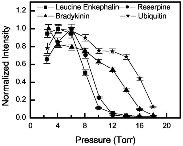
The transmission of Leucine Enkephalin, Reserpine, Bradykinin and Ubiquitin ions as a function of pressure. The data for Bradykinin represent the sum of 2+ and 3+ charge states, while the data for Ubiquitin represent the sum of 7+ to 13+ charge states. Each data set is normalized to its own high intensity point. Both ion funnels were operated at 560 kHz and 70 Vp-p.
The difference between transmissions observed for singly and multiply charged ions is consistent with the fact that the effective potential is higher for multiply charged ions. This observation can be explained by using the following equation that defines the effective potential in vacuum [26, 27].
| (3) |
Here, V*(r, x) represents the effective potential at point (r, x) in cylindrical coordinates; q = ze is the ion charge; ERF(r, x) is the amplitude of the RF electric field that is proportional to the RF voltage VRF applied to the ion funnel; m is the ion mass, and z is the ion charge state. The effective potential is proportional to the ion charge state squared, which explains the charge state-related trend in Figure 2. The effective focusing at elevated pressures can be improved by increasing both γ and the effective potential V*. The γ coefficient can be increased by using higher frequencies (Equation 1). To offset the resulting decrease in effective potential, the RF amplitude needs to be increased accordingly.
High-pressure ion funnel
We designed the high-pressure ion funnel to allow increased RF frequencies and amplitude. To recover the transmission loss at pressures >10 Torr (Figure 2) the high-pressure ion funnel was operated at 1.74 MHz and 40-170 Vp-p. The pressure in the conventional ion funnel vacuum chamber was maintained at 2.0 Torr and the funnel RF was maintained at 560 kHz and 70 Vp-p. The transmission curves shown in Figure 3 for Leucine Enkephalin, Reserpine, the 2+ charge state of Bradykinin, and the 12+ charge state of Ubiquitin as a function of pressure were obtained by leaking additional gas into the high-pressure funnel chamber. Note that other charge states of Bradykinin and Ubiquitin exhibited similar trends in transmission that appear fairly constant up to the maximum pressure studied, i.e., 28-30 Torr. The transmission performance of the high pressure ion funnel at low pressure was comparable to conditions used for the lower pressure regime (i.e. 560 kHz and 70 Vp-p), as shown in Figure 3b for reserpine. This indicates no loss in ion transmission due to the higher RF frequency at low pressure.
Figure 3.
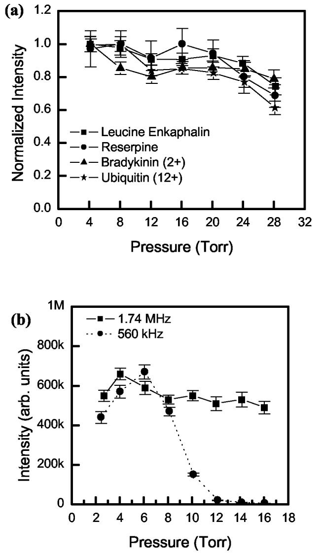
a) Transmission curves for Leucine Enkephalin, Reserpine, Bradykinin and Ubiquitin ions as a function of pressure, using RF of 1.74 MHz and 40-170 Vp-p. Other charge states of Bradykinin and Ubiquitin showed similar transmission. The pressure in the 2nd ion funnel region was maintained at 2.0 Torr. Each data set is normalized to its individual highest intensity point. b) The transmission of high-pressure funnel when operated at 560 kHz, 70 Vp-p and 1.74 MHz, 50-80 Vp-p (adjusted for maximum transmission at each pressure). The pressure in the second ion funnel region was 1.3 Torr. The sample was standard Reserpine. Leucine Enkephalin, Bradykinin and Ubiquitin showed similar results.
Figure 4 shows the change in RF amplitude (Vp-p), which was adjusted at each pressure to maintain maximum transmission, as a function of pressure tested. A linear increase in RF amplitude (slope of ∼ 5 V/Torr) was required to maintain transmission of Leucine Enkephalin and Reserpine at higher pressures. At 28 Torr, the Vp-p is 160-170 V for Leucine Enkephalin and Reserpine, while only a small increase in Vp-p was required for Bradykinin and Ubiquitin (Vp-p = 100-110 V at 28 Torr). This observation is consistent with equation (3) and Figure 2, that both indicate multiply charged molecules result in higher effective potential and as a result, better confinement for multiply charged ions. We did not observe detectable fragmentation of these ions due to RF heating.
Figure 4.
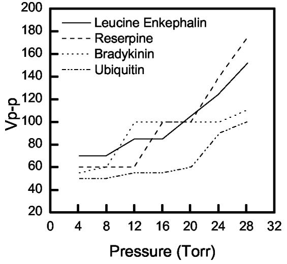
The change in the RF peak-to-peak voltage (Vp-p) as a function of pressure tested. The RF frequency was 1.74 MHz in the high pressure ion funnel.
Implementation of high-pressure funnel with a heated multicapillary inlet
The success in operating the ion funnel at high pressures opens new avenues for increasing ESI-MS sensitivity, such as implementation with a heated multicapillary inlet. ESI is known to produce a cloud of ions that moves toward the mass spectrometer interface [28, 29]. The efficiency of transferring the ESI ions through the inlet capillary depends approximately on the area ratio of the capillary to the spray cross section. The larger the liquid ESI flow rate, the larger the droplet size in electrospray. ESI requires droplet desolvation, and larger flow rates generally require larger gaps between the ESI emitter and the capillary inlet. The electrospray plume expands rapidly in this gap, and as a result, the area of the inlet capillary is much smaller than the area over which ions are dispersed, which lowers the overall ion transmission efficiency [6, 30]. Increasing the diameter of a single capillary becomes inefficient beyond a certain point due to decreased desolvation efficiency.
Multicapillary inlets allow introduction of more ions, particularly from higher flow rate electrosprays while maintaining effective desolvation. The use of a multicapillary inlet increases the gas load, and in turn the pressure, in the ion funnel chamber; however, the increased load reduces the ion transmission efficiency of the conventional ion funnel (Figure 2). The new ion funnel can handle a significantly higher pressure than the conventional funnel without sacrificing ion transmission. The new design includes the use of a jet disrupter, as well as the use of insulating Teflon washers instead of Teflon sheets between electrodes, which reduces the capacitance of the ion funnel since the dielectric constant of air (1.0) is lower than that of Teflon (2.1) [31], and increases the pumping efficiency.
We evaluated a multicapillary inlet composed of 18 capillaries, each with a 430 μm i.d. The gas load through the 18-capillary inlet resulted in a pressure of ∼21 Torr (measured outside the funnel) in the high-pressure funnel vacuum chamber. The actual pressure might be even higher because of gas dynamics. Ion transmission with the new multicapillary inlet was studied as a function of the number of open capillaries and compared to the single capillary inlet. For both inlet configurations (single and multicapillary) the high pressure funnel was operating at 1.80 MHz while the RF amplitude was adjusted (for optimum transmission) between 90 and 150 Vp-p depending on the pressure. The number of open capillaries was varied by blocking the capillaries with aluminum foil.
Figure 5a shows that the ion transmission of the high-pressure ion funnel/single capillary interface is constant across the pressure range studied (4-22 Torr). The ion transmission for the multicapillary inlet initially increases as a function of the number of open capillaries, plateaus in the region of 5-11 capillaries and decreases slightly at 18 capillaries. The improvement in sensitivity is 5-fold compared to that obtained by using the single capillary inlet. The plateau observed in Figure 5a is consistent with maximized sampling of electrosprayed ions for ≥5 capillaries. This assumption was tested by moving the electrospray emitter far from the multicapillary inlet (∼18 mm), which increased the electrospray jet cross section. By sampling the ions at a wider jet cross section area, the number of ions sampled per capillary was also lowered. Accordingly, the sensitivity increased as shown in Figure 5b, almost linearly, as the number of capillaries (up to ∼ 15) increased. This finding directly implies that the sampling efficiency of the multicapillary inlet increases linearly if not limited by the available electrospray current. In other words, if the ESI emitter can produce more current than that presently sampled by only 5 capillaries, then the multicapillary inlet is expected to show >5-fold improvement. The decline in sensitivity shown in Figure 5a for 18 capillaries may be ascribed to the onset of adverse effects due to the intense gas flow out of the multicapillary inlet. This undesirable effect was also reflected on the DC voltage applied to the jet disrupter disk that had to be increased by 30-50V when the multicapillary inlet was used compared with the single capillary inlet.
Figure 5.
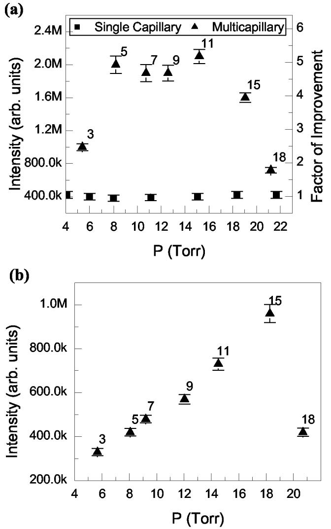
a) A comparison of the peak intensity of standard 1 [.mu]m Reserpine (m/z = 609) obtained using single capillary (filled square) and multicapillary (filled triangle) inlets. Note that the numbers next to the triangle points represents the number of open capillaries in the multicapillary inlet. b) Peak intensity of m/z 609 (Reserpine) as a function of the number of capillaries open. The electrospray emitter was pulled further from the multicapillary inlet such that the number of ions per mm2 is less than that in a). The numbers next to the triangle points represents the number of open capillaries in the multicapillary inlet. The conventional funnel was operating at 560 kHz, 70 Vp-p, and 1.6 Torr while the high-pressure funnel was operating at 1.80 MHz and between 90 and 150 Vp-p, depending on pressure.
We then implemented a 7 capillary inlet (430 μm-i.d., capillaries) (Figure 1) to further evaluate the method we used to vary the number of open capillaries (i.e., plugging with aluminum foil) which may not have provided an accurate estimate for the pressure in the funnel (e.g., possible gas leak). This 7-capillary inlet resulted in a pressure of ∼8 Torr in the ion funnel chamber and a 5-fold enhancement in sensitivity for the standard Reserpine sample compared to the single capillary inlet (Figure 6). Results for Leucine Enkephalin and Bradykinin also showed a 4-fold enhancement, as well as a 2-fold enhancement for Ubiquitin. A <7-fold enhancement in sensitivity is consistent with the observation that the ion density across the electrospray plume is not homogeneous [14, 32].
Figure 6.

A comparison of the mass spectra obtained using heated single capillary and multicapillary (seven capillaries) inlets for a) 1μM of Leucine Enkephalin on the single capillary, b) 1μM of Leucine Enkephalin on the multicapillary, c) 1μM Reserpine on the single capillary, d) 1μM Reserpine on the multicapillary, e) 0.25 μM of Bradykinin on the single capillary, f) 0.25 μM of Bradykinin on the multicapillary, g) 1μM Ubiquitin on the single capillary and h) 1μM Ubiquitin on the multicapillary. All other experimental parameters were kept similar except that the emitter tip position and electrospray voltage were optimized in each mass spectrum to give optimum stable signal.
Conclusion
We developed an ion funnel that maintains a high ion transmission at significantly higher pressures than previous designs. This new funnel operates at 30 Torr, achieved by using an RF frequency of ∼1.7 MHz and amplitude of 100-170 V (peak-to-peak), and can be extended to even higher pressures. Operation at such a high frequency required the removal of excess materials from the ion funnel electrodes, which reduced the total capacitance of the funnel to ∼1.6 nF. A novel tandem ion funnel interface allowed for high pressure operation without compromising ion transmission in the mass spectrometer due to the elevated pressure.
The initial implementation of the high-pressure ion funnel in which the heated single capillary inlet was replaced with a heated multicapillary inlet resulted in a 2 to 5-fold improvement in signal intensity compared to the single capillary/high pressure ion funnel configuration. In turn, the increased signal intensity improved the detection limit and sensitivity of the mass spectrometer. We also showed that by using the multicapillary inlet, the sensitivity can be increased even further if not limited by the available ESI current.
We plan to couple the new ion funnel to an ion mobility spectrometer to increase the operating pressure so as to increase drift tube ion transmission efficiency to ∼100% [19]. In doing so, the resolution of the ion mobility spectrometer can be increased by operating at higher drift voltages. The increased throughput and resolution afforded by this platform holds potential for enabling new biological applications.
Acknowledgements
The authors thank Dr. Jason S. Page, Dr. Fumin Li, and David Prior for extensive and helpful discussions. This research was supported by the U.S. Department of Energy (DOE) Office of Biological and Environmental Research. Experimental work was performed in the Environmental Molecular Sciences Laboratory, a DOE national scientific user facility at the Pacific Northwest National Laboratory (PNNL) in Richland, Washington. PNNL is operated by Battelle for the DOE under Contract No. DE-AC05-76RLO 1830.
References
- 1.Cristoni S, Bernardi LR. Development of New Methodologies for The Mass Spectrometry Study of Bioorganic Macromolecules. Mass Spectrom. Rev. 2003;22:369–406. doi: 10.1002/mas.10062. [DOI] [PubMed] [Google Scholar]
- 2.Smith RD, Shen Y, Tang K. Ultrasensitive and Quantitative Analyses from Combined Separations-Mass Spectrometry for the Characterization of Proteomes. Acc. Chem. Res. 2004;37:269–278. doi: 10.1021/ar0301330. [DOI] [PubMed] [Google Scholar]
- 3.Brown SC, Kruppa G, Dasseux J-L. Metabolomics Applications of FT-ICR Mass Spectrometry. Mass Spectrom. Rev. 2005;24:223–231. doi: 10.1002/mas.20011. [DOI] [PubMed] [Google Scholar]
- 4.Wilm M, Mann M. Analytical Properties of the Nanoelectrospray Ion Source. Anal. Chem. 1996;68:1–8. doi: 10.1021/ac9509519. [DOI] [PubMed] [Google Scholar]
- 5.Fernández de la Mora J, Kloscertales IG. The Current Emitted by Highly Conducting Taylor Cones. J. Fluid Mech. 1994;260:155–184. [Google Scholar]
- 6.Zook DR, Bruins AP. On Cluster Ions, Ion Transmission, and Dynamic Range Limitations in Electrospray (ionspray) Mass Spectrometry. Int. J. Mass Spectrom. Ion Processes. 1997;162:129–147. [Google Scholar]
- 7.Zhou L, Yue B, Dearden DV, Lee ED, Rockwood AL, Lee ML. Incorporation of a Venturi Device in Electrospray Ionization. Anal. Chem. 2003;75:5978–5983. doi: 10.1021/ac020786e. [DOI] [PubMed] [Google Scholar]
- 8.Hawkridge AM, Zhou L, Lee ML, Muddiman DC. Analytical Performance of a Venturi Device Integrated into an Electrospray Ionization Fourier Transform Ion Cyclotron Resonance Mass Spectrometer for Analysis of Nucleic Acids. Anal. Chem. 2004;76:4118–4122. doi: 10.1021/ac049677l. [DOI] [PubMed] [Google Scholar]
- 9.Yang P, Cooks RG, Ouyang Z, Hawkridge AM, Muddiman DC. Gentle Protein Ionization Assisted by High-Velocity Gas Flow. Anal. Chem. 2005;77:6174–6183. doi: 10.1021/ac050711l. [DOI] [PubMed] [Google Scholar]
- 10.Kim T, Udseth HR, Smith RD. Improved Ion Transmission from Atmospheric Pressure to High Vacuum using a Multi-Capillary Inlet and Electrodynamic Ion Funnel Interface. Anal. Chem. 2000;72:5014–5019. doi: 10.1021/ac0003549. [DOI] [PubMed] [Google Scholar]
- 11.Kim T, Tang K, Udseth HR, Smith RD. A Multi-Capillary Inlet Jet Disruption Electrodynamic Ion Funnel Interface for Improved Sensitivity Using Atmospheric Pressure Ion Sources. Anal. Chem. 2001;73:4162–4170. doi: 10.1021/ac010174e. [DOI] [PubMed] [Google Scholar]
- 12.Schneider BB, Douglas DJ, Chen DDY. An Atmospheric Pressure Ion Lens to Improve Electrospray Ionization at Low Solution Flow-Rates. Rapid Commun. Mass Spectrom. 2001;15:2168–2175. [Google Scholar]
- 13.Smith RD, Olivares JA, Nguyen NT, Udseth HR. Capillary Zone Electrophoresis-Mass Spectrometry using an Electrospray Ionization Interface. Anal. Chem. 1988;60:436–441. [Google Scholar]
- 14.Thompson JW, Eschelbach JW, Wilburn RT, Jorgenson JW. Investigation of Electrospray Ionization and Electrostatic Focusing Devices using a Three-Dimensional Electrospray Current Density Profiler. J. Am. Soc. Mass Spectrom. 2005;16:312–323. doi: 10.1016/j.jasms.2004.11.012. [DOI] [PubMed] [Google Scholar]
- 15.Schneider BB, Douglas DJ, Chen DDY. An Atmospheric Pressure Ion Lens That Improves Nebulizer Assisted Electrospray Ion Sources. J. Am. Soc. Mass Spectrom. 2002;13:906–913. doi: 10.1016/S1044-0305(02)00389-6. [DOI] [PubMed] [Google Scholar]
- 16.Shaffer SA, Tang K, Anderson GA, Prior DC, Udseth HR, Smith RD. A Novel Ion Funnel for Focusing Ions at Elevated Pressure Using Electrospray Ionization Mass Spectrometry. Rapid Commun. Mass Spectrom. 1997;11:1813–1817. [Google Scholar]
- 17.Shaffer SA, Prior DC, Anderson GA, Udseth HR, Smith RD. An Ion Funnel Interface For Improved Ion Focusing and Sensitivity Using Electrospray Ionization Mass Spectrometry. Anal. Chem. 1998;70:4111–4119. doi: 10.1021/ac9802170. [DOI] [PubMed] [Google Scholar]
- 18.Kim T, Tolmachev AV, Harkewicz R, Prior DC, Anderson GA, Udseth HR, Smith RD, Bailey TH, Rakov S, Futrell JH. Design and Implementation of a New Electrodynamic Ion Funnel. Anal. Chem. 2000;72:2247–2255. doi: 10.1021/ac991412x. [DOI] [PubMed] [Google Scholar]
- 19.Tang K, Shvartsburg AA, Lee H-N, Prior DC, Buschbach MA, Li F, Tolmachev A, Anderson GA, Smith RD. High-Sensitivity Ion Mobility Spectrometry/Mass Spectrometry Using Electrodynamic Ion Funnel Interfaces. Anal. Chem. 2005;77:3330–3339. doi: 10.1021/ac048315a. [DOI] [PMC free article] [PubMed] [Google Scholar]
- 20.Wyttenbach T, Kemper PR, Bowers MT. Design of a New Electrospray Ion Mobility Mass Spectrometer. Int. J. Mass Spectrom. 2001;212:13–23. [Google Scholar]
- 21.Belov ME, Gorshkov MV, Udseth HR, Anderson GA, Tolmachev AV, Prior DC, Harkewicz R, Smith RD. Initial Implementation of an Electrodynamic Ion Funnel with FTICR Mass Spectrometry. J. Am. Soc. Mass Spectrom. 2000;11:19–23. doi: 10.1016/S1044-0305(99)00121-X. [DOI] [PubMed] [Google Scholar]
- 22.Seymour JL, Syrstad EA, Langley CC, Turecek F. Neutralization-Reionization of Ions Produced by Electrospray: Instrument Design and Initial Data. Int. J. Mass Spectrom. 2003;228:687–702. [Google Scholar]
- 23.Tang K, Lin Y, Matson DW, Kim T, Smith RD. Generation of Multiple Electrosprays Using Microfabricated Emitter Arrays for Improved Mass Spectrometric Sensitivity. Anal. Chem. 2001;73:1658–1663. doi: 10.1021/ac001191r. [DOI] [PubMed] [Google Scholar]
- 24.Shaffer SA, Tolmachev A, Prior DC, Anderson GA, Udseth HR, Smith RD. Characterization of a New Electrodynamic Ion Funnel Interface for Electrospray Ionization Mass Spectrometry. Anal. Chem. 1999;71:2957–2964. doi: 10.1021/ac990346w. [DOI] [PubMed] [Google Scholar]
- 25.Tolmachev AV, Chernushevich IV, Dodonov AF, Standing KG. A Collisional Focusing Ion Guide for Coupling an Atmospheric Pressure Ion Source to a Mass Spectrometer. Nucl. Instrum. Methods Phys. Res., Sect. B. 1997;124:112–119. [Google Scholar]
- 26.Gerlich D. In: State-Selected and State-to-State Ion-Molecule Reaction Dynamics. Part 1. Experiment. Ng C-Y, Baer M, editors. Vol. 82. Wiley; New York: 1992. pp. 1–176. [Google Scholar]
- 27.Tolmachev AV, Kim T, Udseth HR, Smith RD, Bailey TH, Futrell JH. Simulation-Based Optimization of the Electrodynamic Ion Funnel for High Sensitivity Electrospray Ionization-Mass Spectrometry. Int. J. Mass Spectrom. Ion Processes. 2001;203:31–47. [Google Scholar]
- 28.Yamashita M, Fenn JB. Electrospray Ion Source. Another Variation on the Free-Jet Theme. J. Phys. Chem. 1984;88:4451–4459. [Google Scholar]
- 29.Fenn JB, Mann M, Meng CK, Wong SF, Whitehouse CM. Electrospray Ionization-Principles and Practice. Mass Spectrom. Rev. 1990;9:37–70. [Google Scholar]
- 30.Smith RD, Loo JA, Edmonds CG, Barinaga CJ, Udseth HR. New Developments in Biochemical Mass Spectrometry: Electrospray Ionization. Anal. Chem. 1990;62:882–899. doi: 10.1021/ac00208a002. [DOI] [PubMed] [Google Scholar]
- 31.Handbook of Chemistry and Physics. 85 ed. CRC Press; LLC: pp. 2004–2005. [Google Scholar]
- 32.Zhou S, Edwards AG, Cook KD, Van Berkel GJ. Investigation of the Electrospray Plume by Laser-Induced Fluorescence Spectroscopy. Anal. Chem. 1999;71:769–776. [Google Scholar]