Abstract
Shape-memory polymers represent a promising class of materials that can move from one shape to another in response to a stimulus such as heat. Thus far, these systems are dual-shape materials. Here, we report a triple-shape polymer able to change from a first shape (A) to a second shape (B) and from there to a third shape (C). Shapes B and C are recalled by subsequent temperature increases. Whereas shapes A and B are fixed by physical cross-links, shape C is defined by covalent cross-links established during network formation. The triple-shape effect is a general concept that requires the application of a two-step programming process to suitable polymers and can be realized for various polymer networks whose molecular structure allows formation of at least two separated domains providing pronounced physical cross-links. These domains can act as the switches, which are used in the two-step programming process for temporarily fixing shapes A and B. It is demonstrated that different combinations of shapes A and B for a polymer network in a given shape C can be obtained by adjusting specific parameters of the programming process. Dual-shape materials have already found various applications. However, as later discussed and illustrated by two examples, the ability to induce two shape changes that are not limited to be unidirectional rather than one could potentially offer unique opportunities, such as in medical devices or fasteners.
Keywords: active polymer, polymer network, shape-memory polymer, stimuli-sensitive polymer, two-step programming process
A rubber band, which is a polymer network, can be elastically deformed and will snap back into its original shape as soon as the external stress is released. Polymer networks in their rubbery state consist of covalently cross-linked flexible polymer chains that are oriented from a coiled state during deformation. The recovery of the original shape is driven by regaining the entropy that was lost when chains were oriented (1). Primarily, the shape of a polymer network is defined by its chemical cross-links (netpoints). Depending on the type of chain segments, different macroscopic domains can be formed having individual transition temperatures (Ttrans), like glass transition (Tg) and melting (Tm) temperatures (2). When a polymer network is cooled below a Ttrans of a specific domain, this domain is solidified and in this way forms physical cross-links. These physical cross-links can dominate the netpoints, so that a new shape can be fixed. In dual-shape materials (3–8), which have found various applications (9–12), this effect is used for temporary fixation of a second shape by deformation of the polymer network and subsequent cooling under stress. The original, memorized shape can be recovered by reheating above Ttrans.
As a structural concept for triple-shape polymers, we selected polymer networks able to form at least two segregated domains. Although the original shape (C) is defined by netpoints resulting from the cross-linking reaction, shapes A and B are created by a two-step thermomechanical programming process. Shape B is determined by physical cross-links associated to the highest transition temperature Ttrans,B, and shape A relates to the second highest transition temperature Ttrans,A.
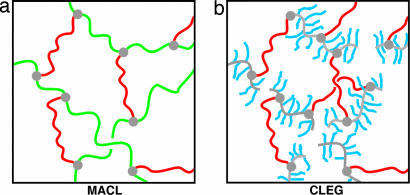
To examine the generality of this approach, two polymer networks differing in their polymer architecture were developed (Fig. 1). The first polymer network system, named MACL, contains poly(ε-caprolactone) (PCL) segments and poly(cyclohexyl methacrylate) (PCHMA) segments. Both types of polymer chain segments form links between netpoints and contribute in this way to the overall elasticity of the polymer network. In the second polymer network system, called CLEG, PEG segments are introduced as side chains having one dangling end and PCL segments connect two netpoints and mainly determine the elasticity of the polymer network. In CLEG networks, Ttrans,B and Ttrans,A are melting temperatures; in MACL, Ttrans,A is a melting and Ttrans,B a glass transition temperature. Both polymer systems are prepared by photoinduced copolymerization of a methacrylate-monomer and poly(ε-caprolactone)dimethacrylate (PCLDMA) (13) as cross-linker. A number average molecular weight Mn of 10,000 g·mol−1 was selected for PCLDMA to obtain highly elastic polymer networks and a comparatively high melting temperature of crystalline PCL domains (Tm,PCL), which is expected to be between 50°C and 60°C (14, 15). In CLEG networks, PEG monomethylether-monomethacrylate (Mn of 1,000 g·mol−1 and a Tm of 38°C) is used as a methacrylate monomer aimed at a melting temperature of crystalline PEG domains (Tm,PEG) lower than Tm,PCL.
Fig. 1.
Polymer network architecture. (a) MACL network. (b) CLEG network. Color coding is as follows: green, PCHMA segments; red, PCL segments; blue, PEG side chains; gray, cross-links.
Results
Thermal and Mechanical Properties.
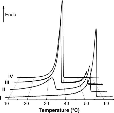
For CLEG networks, two separate melting transitions can be observed in differential scanning calorimetry (DSC) (Fig. 2). Tm,PEG = Ttrans,A increases from 17°C to 39°C with growing PEG content, and Tm,PCL = Ttrans,B is slightly >50°C. Moreover, a Tg for amorphous PCL and PEG domains can be detected around −60°C for all CLEG networks containing at least 30 wt % PCL. MACL networks are synthesized by the copolymerization of PCLDMA with cyclohexyl methacrylate and have a Tm,PCL = Ttrans,A of ≈50°C. The Tg of PCHMA domains, Tg,PCHMA = Ttrans,B, is ≈140°C, which is in accordance with the Tg of high-molecular-weight PCHMA (16), and could be detected by dynamic mechanical analysis at varied temperature for PCLDMA contents up to 45 wt % in the reaction mixture. MACL networks containing >20 wt % PCL also show a Tg of amorphous PCL domains below −60°C. The occurrence of two thermal transitions, Ttrans,A and Ttrans,B, confirms the existence of the required two segregated phases.
Fig. 2.
Thermograms for the second heating run of DSC at a heating rate of 1 K·min−1. Thermograms: I, homonetwork from PCLDMA, CL(100); II, CL(60)EG; III, CL(30)EG; IV, homopolymer from PEG monomethylether-monomethacrylate, graft-EG.
The mechanical properties of the networks were determined by tensile tests at temperatures Tlow, Tmid, and Thigh. For MACL networks −10°C, 70°C, and 150°C, and for CLEG networks 0°C, 40°C, and 70°C were selected. The temperatures were chosen in a way that heating from Tlow to Tmid recovers shape B and further heating to Thigh finally recovers shape C. Sufficient elastic properties needed for triple-shape programming of the sample without breakage at Thigh and Tmid, indicated by values for the elongation at a break of at least 90%, are obtained for all polymer networks having PCLDMA cross-linker contents of at least 30 wt % in the reaction mixture. Values for the Young's modulus decrease with increasing temperature showing the softening of the samples by exceeding a certain Ttrans.
Triple-Shape Properties.
In the beginning of the two-step programming process for creating shapes B and A, the polymer network is heated to Thigh, at which the material is in an elastic state, and is deformed. When the material is cooled to Tmid and external stress is maintained, physical cross-links are established. In MACL networks these cross-links are formed by freezing the PCHMA domains; in CLEG networks, the cross-links are formed by partially crystallizing the PCL segments. Releasing the external stress results in shape B. In the second step, shape A is created. The sample, which presently is in shape B, is further deformed at Tmid. Cooling under external stress to Tlow leads to a second set of physical netpoints: Crystalline domains are formed by PCL segments in MACL networks and by PEG segments in CLEG networks. These new physical cross-links stabilize shape A, which the material takes when the external stress is released. Reheating to Thigh recovers shapes B and C sequentially.
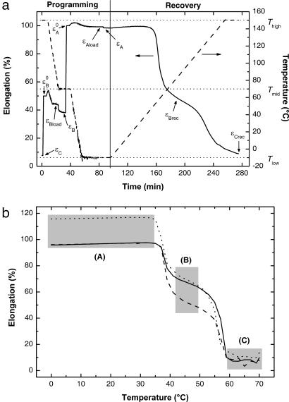
For characterization of the triple-shape effect a specific cyclic, thermomechanical experiment was developed (see Materials and Methods). In each cycle, the two additional shapes (B and A) are created by a two-step uniaxial deformation, followed by recalling shape B and finally shape C. A typical result obtained from cyclic, thermomechanical tests for a MACL network is shown in Fig. 3a.
Fig. 3.
Cyclic, thermomechanical experiments. (a) MACL (45) (fifth cycle) as a function of time. The solid line indicates strain; the dashed line indicates temperature. The variables are explained in Materials and Methods. (b) εT diagram showing the recovery of shapes B and C in cyclic, thermomechanical experiments (third cycle) for CL(40)EG for different combinations of εB0 and εA0: solid line, εB0 = 50% and εA0 = 100%; dashed line, εB0 = 30% and εA0 = 100%; dotted line, εB0 = 50% and εA0 = 120%.
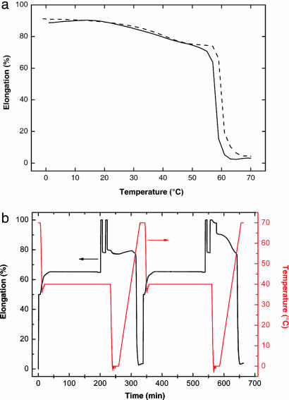
The triple-shape functionality requires pronounced physical cross-links from both domains, defining a composition range in which phase-segregated polymer networks show triple-shape properties. For MACL networks, the recovery of two distinct shapes is observed for PCL contents between 40 and 60 wt %; for CLEG networks recovery is observed between 30 and 60 wt %. If the pure PCL homonetwork or a CLEG network with a low PEG content is programmed, shape B cannot be recovered. For these networks, the material goes immediately to shape C when Tm,PCL is reached. A slight contraction within a broad temperature interval between 23°C and 53°C is caused by PCL crystallites melting in a temperature interval that is lower than Tm,PCL (Fig. 4a).
Fig. 4.
Cyclic, thermomechanical experiments. (a) Recovery curves (third cycle) for CL(70)EG (solid line) and CL(100) (dashed line) after application of a triple-shape programming process with εB0 = 50% and εA0 = 100%. (b) Strain (black) and temperature (red) as a function of time for CL(100) illustrating the effect of cold drawing of PCL segments on the recovery properties.
In CLEG networks, shape B is fixed by crystalline PCL domains. When shape A is created, a deformation is performed at Tmid, which is below Tm,PCL. Thereby flexible, amorphous PCL chain segments are oriented, which can lead to strain-induced crystallization of these segments. To investigate the influence of strain-induced crystallization of PCL segments on shape B as well as on the recoverability of shape C, an additional thermomechanical experiment was performed with a PCL homonetwork. This homonetwork was selected to exclude the influence of semicrystalline PEG (Fig. 4b). The experiment consisted of a sequence of two slightly different thermocycles. In the first cycle, the influence of a deformation after fixation of a temporary shape by crystalline PCL domains was investigated. The temporary shape was fixed analogously to the first step of triple-shape experiments, with εB0 = 50%, resulting in εB after cooling to a Tmid of 40°C and unloading of the sample. At this point, the sample was further elongated by an additional 50%, resulting in a total of ε = 100%. Subsequent unloading to a stress of 0 MPa resulted in an additional contribution to εB of ≈15% fixed strain, which could be explained by the formation of additional PCL crystallites. This effect stays unchanged after repeating the loading–unloading process an additional time. Cooling to Tlow = 0°C followed by reheating to 70°C results in complete recovery of shape C. The second thermocycle was performed to analyze the influence of low-melting-temperature PCL crystallites formed under strain at 100% by cooling to 0°C. For this purpose, the procedure of the first cycle is repeated up to the point when the sample is deformed for the second time to ε = 100%. This time the stress is kept constant while the sample is cooled to Tlow = 0°C. This process leads to a further increase of the fixed strain by 10%, resulting in an overall additional fixed strain of 25%, which is caused by formation of low-melting-temperature PCL crystallites. In the following heating process, a slight contraction (related to this additional 10% fixed strain) of the sample in a broad temperature interval between 15°C and 53°C can be observed as discussed before for Fig. 4a. Further heating to Thigh = 70°C finally leads to a complete recovery of shape C. At this point, crystallites generated by cooling under strain and by strain-induced crystallization are melted.
From the results of this thermomechanical experiment, it can be concluded for the triple-shape programming of CLEG networks that additional PCL crystallites are formed by strain-induced crystallization during the creation of shape A. These PCL crystallites contribute to the fixed strain of shape B and lead to an increase of εB. In addition to PEG crystallites, the formation of low-melting-temperature PCL crystallites during cooling from Tmid = 40°C to Tlow = 0°C contributes to the fixation of shape A.
Cyclic, thermomechanical experiments allow the quantification of the triple-shape effect, including determination of the shape fixity ratio [Rf(X→Y)] and the shape recovery ratio [Rr(X→Y)]. Rf(X→Y) is a measure for the fixability of shape Y after thermomechanical programming starting from shape X (8). Rr(X→Y) describes to what extent shape Y can be recovered starting from shape X (12). R̄f (X→Y) and R̄r(X→Y) are the average values for cycles 2–5 (the first cycle is needed to delete the thermomechanical history originating from sample preparation).
All polymer networks listed in Table 1are triple-shape materials. R̄f(C→B) for CLEG networks increases with increasing PCL content, which supports the fixation of shape B. Accordingly, the contrary tendency can be found for the dependence of R̄f(B→A) from the PCL content. An analogous trend can be found for MACL networks, where R̄f(C→B) increases with increasing content of the component forming the domain related to Ttrans,B, in this case PCHMA. All values for R̄f(C→B) for CLEG networks are >90%. R̄f(C→B) for MACL networks is lower, especially in case of high PCL contents. This different behavior of the two polymer network systems can be explained by the network architecture. The overall elasticity in CLEG networks is determined only by PCL segments, whereas in MACL networks both segment types contribute to the elasticity. When a sample of MACL networks is deformed at Thigh = 150°C, both segment types are oriented. Cooling to Tmid = 70°C solidifies only PCHMA domains. Because Tmid is above Tm,PCL, the elastic deformation of PCL segments is recovered when the stress is released and thereby reduces R̄f(C→B).
Table 1.
Triple-shape properties of polymer networks
| Sample ID | R̄f(C→B),* % | R̄f(B→A),* % | R̄r(A→B),† % | R̄r(A→C),† % |
|---|---|---|---|---|
| CL(30)EG | 90.5 ± 0.8 | 99.1 ± 0.1 | 85.0 ± 2.3 | 99.7 ± 5.5 |
| CL(40)EG | 93.2 ± 0.2 | 98.8 ± 0.1 | 80.8 ± 1.8 | 98.3 ± 5.6 |
| CL(50)EG | 95.8 ± 0.1 | 97.4 ± 0.2 | 73.1 ± 1.8 | 100.7 ± 2.7 |
| CL(60)EG | 97.9 ± 0.1 | 93.2 ± 0.1 | 67.8 ± 1.1 | 100.8 ± 1.0 |
| MACL(40) | 87.1 ± 1.9 | 98.3 ± 0.2 | 88.3 ± 0.6 | 100.6 ± 2.4 |
| MACL(45) | 84.4 ± 4.4 | 98.1 ± 0.8 | 89.9 ± 3.2 | 98.1 ± 7.7 |
| MACL(50) | 63.0 ± 1.4 | 99.1 ± 0.2 | 96.0 ± 0.5 | 101.6 ± 2.2 |
| MACL(60) | 48.1 ± 4.0 | 99.4 ± 0.1 | 94.8 ± 0.8 | 98.4 ± 1.7 |
Average values (cycles 2–5) of triple-shape properties determined by cyclic, thermomechanical experiments for εB0 = 50% and εA0 = 100%. The errors shown are ± SD. The two-digit numbers in parentheses given for the sample IDs are the content of PCLDMA in the reaction mixture in wt %.
*Rf(X→Y) = (εy − εx)/(εyload − εx).
†Rr(X→Y) = (εx − εyrec)/(εx − εy).
All triple-shape materials show almost complete total recovery R̄r(A→C). For CLEG networks, values for R̄r(A→B) decrease with increasing PCL content. This could be explained by additional strain-induced crystallization of amorphous PCL chain segments as described before. For MACL networks, values for R̄r(A→B) are higher compared with the CLEG networks and increase with growing PCL content as expected.
The stability of shape B after recovering from shape A as an important characteristic of a triple-shape material is demonstrated by interrupting the recovery heating run at Tmid and keeping this temperature for 48 h. The elongations of the tested samples did not change unless the temperature is increased afterward to Thigh.
For a triple-shape polymer with a given shape (C), it is possible to create different shapes (A and B) by a variation of εB0 and εA0 in the programming process, as demonstrated for a CLEG network (Fig. 3b). In two experiments, εB0 is 50%, whereas εA0 is varied. In both cases, the recovered shapes (B) have the same elongation and are therefore independent from the programmed shape (A). For the two experiments with εA0 = 100%, shape B is varied. Here the recovered shapes (B) have different elongations. Independent from the programming of shapes A and B, the identical shape (C) is recovered for all samples.
All investigated materials showing a triple-shape effect also can be used as dual-shape materials by performing dual-shape experiments (17) either between Tlow and Tmid using Ttrans,A or between Tmid and Thigh using Ttrans,B. Vice versa, not all materials with two domains exhibiting independent Ttrans,A and Ttrans,B show a triple-shape effect, as could be demonstrated for polymer networks CL(70)EG (Fig. 4a) and CL(80)EG. Although these polymer networks show two independent dual-shape effects using either Tm,PEG or Tm,PCL, they do not show a triple-shape effect. A variety of approaches for polymer networks with two thermal transitions get a dual-shape effect, but none of them has demonstrated the triple-shape effect (3, 8, 18, 19)
Conclusion
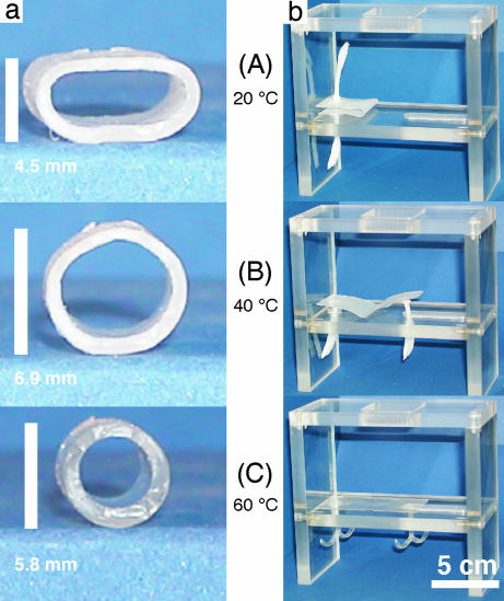
Polymers with triple-shape functionality might enable applications in various fields because their properties can be adjusted over a wide range. Two examples for potential applications are visualized in Fig. 5 using the CLEG network. In Fig. 5a, a tube that can sequentially expand and contract is shown, which demonstrates that the two subsequent shape changes are not necessarily unidirectional. This technology could enable the design of a removable stent (Movie 1, which is published as supporting information on the PNAS web site), which can be inserted in the body in a compressed shape (A). When placed at a desired position, the device can be expanded to shape B and at a later point in time contracted to shape C to facilitate removal. Ttrans,B and Ttrans,A can be adjusted to the demands of a specific application by variation of the molecular weight of PCLDMA and PEG monomethylether-monomethacrylate. In Fig. 5b, an intelligent fastener is presented (Movie 2, which is published as supporting information on the PNAS web site) that can potentially be used in assembly technology to fix a specific component, e.g., a cable harness at positions that are difficult to access. The monolithic device (the manufacturing process, see Figs. 6–8, which are published as supporting information on the PNAS web site) is placed in a compact easy to handle form (A) to the right position that might be difficult to access. After unfolding and positioning (B) the anchors of the fastener open (C).
Fig. 5.
Series of photographs illustrating the triple-shape effect. Two different demonstration objects prepared from CL(50)EG: tube (a); fastener consisting of a plate with anchors (b). The picture series show the recovery of shapes B and C by subsequent heating to 40°C and 60°C, beginning from shape A, which was obtained as a result of the two-step programming process.
Materials and Methods
Synthesis.
PCLDMA synthesized according to ref. 14 was mixed with the respective comonomer and melted in a vacuum oven. The melt was filled between two glass plates with a Teflon spacer having a thickness of 0.5 mm, photocured with a System F300M (Fusion UV Systems, Gaithersburg, MD) equipped with a high-pressure mercury lamp at a light intensity of ≈122 mW·cm−1. The distance between lamp head and sample was 25 cm. The samples were finally extracted with chloroform.
DSC.
DSC experiments were performed on a DSC 204 (Netzsch, Selb, Germany). All experiments were performed with a constant heating and cooling rate of 10 K·min−1 for the detection of glass transitions and with 1 K·min−1 for the detection of melting transitions. Whenever a maximum or minimum temperature in the testing program was reached, this temperature was kept constant for 2 min. The CLEG networks were investigated in the temperature range from −100°C to 80°C. The sample was heated from 20°C to 80°C, then cooled down to −100°C and again warmed up to 80°C. The transitions were determined from the second heating run.
Dynamic Mechanical Analysis at Varied Temperature.
The determination of the dynamic mechanical properties was performed on an Eplexor 25 N (Gabo, Ahlden, Germany). All experiments were performed in temperature-sweep mode, with a constant heating rate of 2 K·min−1. The oscillation frequency was 10 Hz. MACL networks were investigated in the temperature interval from −100°C to 100°C. Tg,PCHMA was determined from the maximum peak temperature of the tanδ curve.
Tensile Tests and Cyclic, Thermomechanical Experiments.
These experiments were carried out on a Z005 (Zwick, Ulm, Germany) for CLEG networks and a Z1.0 for MACL networks equipped with thermochambers controlled by Eurotherm control units (2216E for the Z005 and 2408 for the Z1.0, Eurotherm Regler, Limburg, Germany). Load cells suitable to determine maximum forces of 200, 100, and 20 N were used depending on samples and temperature. Films were cut into standard samples (ISO 527–2/1BB) and strained at an elongation rate of 10 mm·min−1.
In a triple-shape experiment (Fig. 3a), the sample is stretched at Thigh from εC, where the elongation corresponds to shape C, to εB0. Cooling with a cooling rate (βc) of 5 K·min−1 to Tmid under stress-control results in εBload. Unloading after 180 min for CLEG networks and 30 min for MACL networks leads to εB, which is shape B. The sample is further stretched to εA0 and cooled to Tlow under stress-control with βc = 5 K·min−1, whereas the elongation decreases to εAload. Shape A, corresponding to εA, is obtained by unloading after 10 min for CLEG networks and 20 min for MACL networks. The recovery process of the sample is monitored by reheating with a heating rate of 1 K·min−1 from Tlow to Thigh while the stress is kept at 0 MPa. The sample contracts to recovered shape B at εBrec, which is defined as the elongation at the minimum contraction rate. Continued heating finally leads to recovery of shape C at εCrec. This cycle is conducted five times with the same sample.
Supplementary Material
Abbreviations
- PCHMA
poly(cyclohexyl methacrylate)
- PCL
poly(ε-caprolactone)
- PCLDMA
poly(ε-caprolactone) dimethacrylate
- DSC
differential scanning calorimetry.
Footnotes
Conflict of interest statement: R.L. and A.L. have equity in and serve on the advisory board of mNemoscience, which holds certain patents regarding shape-memory polymers.
References
- 1.Flory PJ, Rehner J., Jr J Chem Phys. 1943;11:512–520. [Google Scholar]
- 2.Flory PJ, Mandelkern L, Mark JA, Suter UW. Selected Works of Paul J Flory. Stanford, CA: Stanford Univ Press; 1985. [Google Scholar]
- 3.Reyntjens WG, Du Prez FE, Goethals EJ. Macromol Rapid Commun. 1999;20:251–255. [Google Scholar]
- 4.Kim BK, Lee SY, Xu M. Polymer. 1996;37:5781–5793. [Google Scholar]
- 5.Lendlein A, Kelch S. Angew Chem Int Ed. 2002;41:2034–2057. [PubMed] [Google Scholar]
- 6.Hayashi S, Kondo S, Kapadia P, Ushioda E. Plast Eng. 1995;51:29–31. [Google Scholar]
- 7.Gall K, Yakacki CM, Liu Y, Shandas R, Willett N, Anseth KS. J Biomed Mater Res. 2005;73A:339–348. doi: 10.1002/jbm.a.30296. [DOI] [PubMed] [Google Scholar]
- 8.Li FK, Zhu W, Zhang X, Zhao CT, Xu M. J Appl Polym Sci. 1999;71:1063–1070. [Google Scholar]
- 9.Metcalfe A. Biomaterials. 2003;24:491–497. doi: 10.1016/s0142-9612(02)00362-9. [DOI] [PubMed] [Google Scholar]
- 10.El Feninant F, Laroche G, Fiset M, Mantovani D. Adv Eng Mater. 2002;4:91–104. [Google Scholar]
- 11.Monkman GJ. Mechatronics. 2000;10:489–498. [Google Scholar]
- 12.Tobushi H, Hara H, Yamada E, Hayashi S. Smart Mater Struct. 1996;5:483–491. [Google Scholar]
- 13.Aoyagi T, Miyata F, Nagase Y. J Control Release. 1994;32:87–96. [Google Scholar]
- 14.Lendlein A, Schmidt AM, Schroeter M, Langer R. J Polym Sci Part A: Polym Chem. 2005;43:1369–1381. [Google Scholar]
- 15.Zhu G, Liang G, Xu Q, Yu Q. J Appl Polym Sci. 2003;90:1589–1595. [Google Scholar]
- 16.Wu S. J Appl Polym Sci. 1992;46:619–624. [Google Scholar]
- 17.Choi N-Y, Kelch S, Lendlein A. Adv Eng Mater. 2006;8:439–445. [Google Scholar]
- 18.Goethals EJ, Reyntjens W, Lievens S. Macromol Symp. 1998;132:57–64. [Google Scholar]
- 19.Liu GQ, Ding XB, Cao YP, Zheng ZH, Peng YX. Macromol Rapid Commun. 2005;26:649–652. [Google Scholar]
Associated Data
This section collects any data citations, data availability statements, or supplementary materials included in this article.


