

Abstract
Protein-protein interactions play a pivotal role in biological signaling networks. It is highly desirable to perform experiments that can directly assess the oligomerization state and degree of oligomerization of biological macromolecules in their native environment. Homo-FRET depends on the inverse sixth power of separation between interacting like fluorophores on the nanometer scale and is therefore sensitive to protein oligomerization. Homo-FRET is normally detected by steady-state or time-resolved fluorescence anisotropy measurements. Here we show by theory and simulation that an examination of the extent of homotransfer as measured by steady-state fluorescence anisotropy as a function of fluorophore labeling (or photodepletion) gives valuable information on the oligomerization state of self-associating proteins. We examine random distributions of monomers, dilute solutions of oligomers, and concentrated solutions of oligomers. The theory is applied to literature data on band 3 protein dimers in membranes, GPI-linked protein trimers in “rafts,” and clustered GFP-tagged epidermal growth factor receptors in cell membranes to illustrate the general utility and applicability of our analytical approach.
INTRODUCTION
The oligomerization of protein macromolecules on cell surfaces is believed to play a fundamental role in the regulation of cellular function, including signal transduction and the immune response (1–4). Because of the perceived importance of macromolecular oligomerization as a biological control mechanism, it is essential to perform experiments that can quantitatively assess the oligomerization states and extent of clustering on the nanometer scale (relevant to molecular contact).
The quantification of oligomerization on and inside cells is a difficult problem. Experimental strategies appropriate to cell and membrane preparations include measurement of protein translational and rotational diffusion (5) and fluorescence fluctuations in space (6) and/or time (7) by correlation spectroscopy/microscopy and intermolecular proximity between donor-labeled and acceptor-labeled proteins by fluorescence resonance energy transfer (8). In the latter situation, the characteristic nanometer distance scale of the energy transfer phenomenon renders it a particularly sensitive probe of protein association between fluorescently tagged proteins.
Homo-FRET, particularly energy migration FRET (9,10), is a simpler variant of energy transfer because it occurs between like chromophores and hence requires only one type of fluorescent label. It is manifested by the presence of depolarized fluorescence. Beginning with the first reported observation of concentration-dependent depolarization by Gaviola and Pringsheim (11), there exists a wide application of the phenomenon to photosynthesis, light-harvesting polymers, as well as synthetic and natural polychromophoric arrays (12). Much of the theoretical descriptions have focused on extracting information on interchromophore distance distributions from analysis of high-resolution time-resolved fluorescence anisotropy decay measurements (13). The descriptions result in complex decay functions that require data of high signal/noise ratio on samples of high purity. This circumstance is difficult to achieve in the complex milieu of the living cell and requires specialized instrumentation that is not readily available in most biological laboratories.
A simpler approach in terms of experimental implementation is to use steady-state anisotropy. Runnels and Scarlata have shown that under certain conditions the steady-state anisotropy is inversely proportional to the number of subunits in the oligomer (14). However, anisotropy as a single measure suffers from ambiguity of interpretation since factors other than energy transfer, such as excited state lifetime changes or changes in rotational motion, can hyper- or hypopolarize the emission. Several groups have reported cellular anisotropy measurements as a function of labeling (or photobleaching) as a qualitative probe of energy homotransfer. In the anisotropy enhancement after photobleaching experiment, first applied by the Mayor group (15), any depolarization caused by energy transfer is reversed by photodestruction of FRET acceptors (15). Similarly, mixing of labeled and unlabeled proteins should reverse interaction-dependent depolarization processes, as shown by Blackman et al. (16). In principle, these measurements allow information beyond confirmation of energy transfer and proximity to be obtained.
Our examination of the extent of energy migration as measured by fluorescence anisotropy as a function of fluorophore labeling (or photodepletion) gives valuable information on the actual oligomerization state of self-associating proteins. In the next section we present a general theoretical model for interpreting anisotropy data in terms of dilute solutions of oligomers and oligomerization distributions. The model predicts that the anisotropy as a function of labeling for an oligomer with N subunits is a polynomial of order N−1. We extend the formalism to account for the occurrence of interoligomer energy transfer and specifically treat interdimer energy transfer. This extension is needed because of the possible occurrence of depolarization between overexpressed oligomeric proteins at high density in cell membranes. In the Examples section we use our analytical methods to examine existing data from the literature on both intra- and interoligomer energy transfer between Band 3 dimers in solution and on membranes, intraoligomer energy transfer between triproximal GPI-proteins in rafts, and the consequences of submicrometer scale clustering of EGFR-eGFP on anisotropy enhancement data after photobleaching data.
THEORY
Theory of homo-FRET between interacting fluorophores
Self-association of proteins causes changes to the anisotropy of the fluorescent tags. Because of the energy homotransfer (lower anisotropy) or changes in rotational diffusion of the fluorescent label (lower or higher anisotropy) or a combination of both oligomers and monomers have different levels of anisotropy. The interpretation of a single anisotropy measurement is ambiguous. However, varying the extent of fluorophore labeling allows processes leading to energy homotransfer to be monitored separately from rotational diffusion (15,16). The exchange of labeled for unlabeled molecules would not be expected to alter the inherent motional properties of fluorophores, but it does decrease the probability for self-transfer of energy.
Dilute solution of homogeneous oligomers
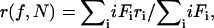
First, we consider a single population of oligomers with N monomer subunits per oligomer. For a structure with N subunits, the fraction Fi that have i fluorescently labeled subunits when a fraction f of the subunits are labeled is, according to the binomial theorem (17,18),
 |
(1) |
The total anisotropy of the oligomer population as a function of labeling (f) is given by the sum law of anisotropies (10), where the summation is from i = 1 to i = N:
 |
(2) |
where ri is the anisotropy of the N-mer bearing i-labeled subunits. Consequently, the anisotropy expressions for a dimer, trimer, tetramer, and N-mer are given as follows:
 |
(3) |
 |
(4) |
 |
(5) |
 |
(6) |
These expressions are obtained by noting that for an N-mer one has a polynomial of order N − 1 with the coefficients in the expansion (A1, A2, … AN) derived from the (N − 1)th row of the Pascal's triangle.
These equations are general and make no assumptions about the energy transfer or rotational dynamics properties of the fluorophores. The only requirement is that an oligomer with one subunit labeled yields a different fluorescence anisotropy than an oligomer containing more than one fluorescently labeled subunit. Runnels and Scarlata have provided a means of determining the anisotropy of an oligomeric protein as a function of the number of labeled subunits (14) from structural data.
Fig. 1 illustrates simulations of the anisotropy as a function of labeling for a monomer, dimer, and tetramer under the situation that energy migration depolarizes the fluorescence to an extent that the anisotropy is decreased to r1/N, where N is the number of labeled monomers per oligomer. This choice of anisotropy corresponds to the limit of efficient energy hopping (14) between randomly oriented but rotationally fixed fluorophore sites. This circumstance is achieved at separations of less than 0.8 Ro, where Ro is the Förster distance (e.g., ∼5 nm for eGFP). It is notable that the oligomerization state is reflected in the curvature of the anisotropy as a function of labeling plot, a consequence of Eq. 3–5.
FIGURE 1.

Simulations of the anisotropy as a function of labeling (f) for discrete oligomers (containing N-subunits) under the situation that energy migration depolarizes the fluorescence to an extent that the anisotropy is decreased to rm/N, where N is the number of labeled monomers per oligomer. N-values in order from top to bottom: N = 1, 2, 3, … , 8. Simulations generated using Eq. 6 in text, with r1 = 0.4.
Oligomerization state distributions
In the general case of a distribution of oligomers, the anisotropy of the population is given by the appropriately weighted mean of the individual anisotropies of the oligomers. Consider a distribution of oligomers with oligomerization states 1 to N, each with molar fraction χN. The mean anisotropy as a function of labeling is given by
 |
(7) |
The influence of the Poisson distribution of oligomerization states is presented in Fig. 2 using the same model as in Fig. 1 for N = 1, 2, 3, and 4. The corresponding single population oligomerization model is plotted for comparison. For all N, the Poisson model gives anisotropy plots that show greater curvature than the homogeneous model. This is because in the distributed oligomer case, Eq. 7 receives weighting from states of higher oligomer number. For the Poisson simulations presented in Fig. 2, the fluorescence population distribution of oligomers contains modes at N and N + 1. Parenthetically we note improved agreement using a Poisson model with mean oligomerization 〈N〉 = N − 0.5 with a homogeneous model with oligomerization state N. In this case both models have a single mode at N.
FIGURE 2.

Comparison of anisotropy as a function of fluorophore labeling for homogeneous oligomers with N subunits (dotted lines) and a Poisson distribution of oligomers with mean oligomerization number of N (solid lines). N-values in order from top to bottom: N = 1, 2, 3, and 4. Simulations generated with Eqs. 6 and 7 in text using the model in Fig. 1.
Minimum degree of oligomerization and oligomeric state
In the context of a simple two-state bimodal monomer–N-mer model, it is possible to derive estimates of the minimum degree of oligomerization and minimum number of subunits in the oligomer. A conservative estimate of the oligomerization state (N) and minimum degree of oligomerization (1 − x) is obtained if we take the anisotropy of oligomers containing two or more fluorescently labeled subunits as zero. This is the limit where the monomer has a finite anisotropy but in the oligomer population there is large loss of polarization as a result of extensive energy migration and rotational diffusion. When Eqs. 1 and 2 are combined, the anisotropy in a population of oligomers is then given simply by
 |
(8) |
where rm is the anisotropy of a noninteracting fluorophore, x is the (constant) fractional fluorescence from noninteracting fluorophores (monomeric complexes), and f represents the fractional labeling of the fluorophore population. Equations similar to Eq. 8 have also been derived for conventional donor-acceptor energy transfer and electron spin resonance measurements of protein oligomerization in model membranes (17,18).
The effect of monomer on the anisotropy enhancement curves is shown for the situation of a bimodal monomer-tetramer equilibrium (Fig. 3). The presence of the monomer rescales the anisotropy plot by a constant value but does not change its shape. This is an important property of the anisotropy enhancement method; only sources of depolarization that result from homo-FRET are affected by labeling/bleaching. Thus, oligomerization states of proteins that are in equilibrium between monomeric and associated (oligomeric or concentrated) forms can be investigated. Simulations with the Poisson-distributed model and rN = rm/N show that Eq. 8 always yields a minimum estimate of the mean oligomerization state.
FIGURE 3.

The effect of monomer on the anisotropy enhancement curves. Monomer-tetramer equilibrium with increasing fraction of fluorescence caused by monomer: 75% monomer (circles), 50% monomer (squares), 25% monomer (triangles). Simulations generated with Eq. 8 from text.
Random distributions: concentration depolarization effects
It is possible, in cases of protein overexpression or at high protein/lipid ratios in reconstituted systems, that the occurrence of homo-FRET does not result from oligomerization at all, but rather by close approach of randomly organized monomeric proteins. Although this circumstance can be avoided by dilution in reconstituted or synthetic systems, this is potentially problematic in cell systems, particularly where cells express high levels of protein at the membrane. The cases for 2D energy migration between randomly organized systems has been documented previously (19). The equation for 2D transfer depolarization between monomers is:
 |
(9) |
where τ is the fluorescence lifetime and β is the normalized 2D concentration of monomers (= 1.354C/2Co, where C/Co is the average number of monomers per circular area with radius equal to the Förster distance  For a typical Förster distance of 5 nm, a cell expressing 1 million receptors on the cell surface (typical cell surface area ranges 1000–10,000 μm2) will have a normalized 2D concentration of β = 0.008–0.08 molcules/Förster area. Simulations presented below show the extent to which these effects are anticipated to influence the measured anisotropy.
Concentrated 2D solution of homogeneous oligomers
We consider the oligomers to be homogeneous and preformed. (The reader is referred to the article by Jovin et al. (20) for the 3D monomer-dimer equilibrium case as a function of concentration.) It is instructive to consider the situation of concentration depolarization of oligomers. This can be readily treated under the reasonable assumption that intraoligomer and interoligomer energy transfer modes of depolarization are independent (21).
The time-dependent anisotropy of the system involving both intraoligomer and interoligomer transfers is given by:
 |
(10) |
where r(t)oligomer is the anisotropy decay caused by intraoligomer energy transfer (and rotation), and the exponent term accounts for interoligomer energy transfer between randomly organized oligomers. Note, the term βo in this context refers to the normalized 2D concentration of oligomers (as opposed to monomers).
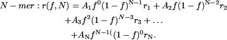
The consequences of energy transfer between like chromophores on the fluorescence and anisotropy decays within a dimer has been discussed by Tanaka and Mataga (22). For a fixed dimer geometry the time-resolved anisotropy is described by a single exponential decaying to a finite value:
 |
(11) |
Here, ro is the anisotropy in the absence of rotation or energy transfer, and r∞ is the anisotropy at a long time after the excitation (i.e., 200 ns or longer). The transfer correlation time, φ, is related to the rate of energy transfer (w) by φ = (2w)−1.
Combining the two terms and following similar arguments as discussed above gives the following anisotropy decay expression for randomly organized dimers as an explicit function of dimer concentration (β) and fractional labeling (f):
 |
(12) |
Equations describing higher-order oligomerization states can also be readily derived using appropriate time-dependent versions of Eqs. 3–6 for r(t)oligomer and noting that the effective concentration of labeled oligomers (i.e., bearing one or more labeled subunits) is given by β(1 − (1 − f)N).
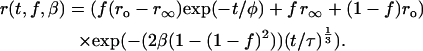
The steady-state anisotropy is obtained on integration with the intensity decay function I(t):
 |
(13) |
Implicit in Eq. 13 is the independence of the intensity decay to concentration or labeling effects (i.e., the absence of concentration quenching).
The influence of a concentrated solution of monomers on the anisotropy versus label plot is shown in Fig. 4 for the situation where there are 1 million molecules on the surface of a cell with surface area 1000 μm2 (β = 0.075). The maximum extent of depolarization, compared with a dilute monomer solution model is 0.04. The corresponding plots for 1 million dimers on a cell with surface area 1000 μm2 is shown for comparison (with ro = 0.4, r∞ = 0.2, w = 1 ns, τ = 4 ns) in the presence (β = 0.075) and absence (β = 0) of concentration depolarization. Concentration depolarization decreases the anisotropy at all label efficiencies compared with the dilute dimer situation but does not cause the anisotropy versus labeling curve to deviate substantially from a linear relationship. This is expected to be general whenever the intradimer energy migration is the dominant depolarization process. Thus, it is reasonable to expect that a significant curvature in the anisotropy versus labeling curve is a reflection of either 1), an atypically high local concentration of monomeric protein or 2), association at a level greater than dimer.
FIGURE 4.

The effect of 2D concentration on the anisotropy versus label plot. Monomers at 1 million molecules on the surface of a cell with surface area 1000 μm2 (β = 0.075) (circles). Dimers at a concentration of 1 million dimers on a cell with surface area 1000 μm2 (with ro = 0.4, r∞ = 0.2, w = 1 ns, τ = 4 ns) in the presence (β = 0.075) (triangles) and absence (β = 0) (squares) of concentration depolarization.
Concentrated 3D solution of homogeneous dimers
The case of 3D concentration depolarization of dimers is analytically tractable, and for brevity we present the results. In this case, the interoligomer term in Eq. 10 is given by 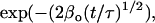 and the steady-state anisotropy r is expressed in Eq. 14:
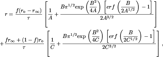 |
(14) |
where A = (φ−1 + τ−1), B = 2β[1 − (1 − f)2] / t½, and C = τ−1.
In the absence of concentration depolarization (β = 0), a linear relationship exists between r and f with a constant gradient, Gβ=0 = [(ro − r∞) / τ(φ−1 + τ−1)] + r∞ − ro. Fig. 5 shows the variation of the gradient (G) for the r versus f curve at various f values for β = 0, 0.001, 0.01, and 0.1, and ro = 0.4, r∞ = 0.2, w = 1 ns and τ = 4 ns. We note that for low dimer concentrations (i.e., β = 0.001), the G values remain close to Gβ=0 (= −0.133) regardless of the degree of fluorescence labeling (f). By way of orientation, a concentration of 10–100 μM corresponds to β = 0.001–0.01 (for a fluorophore with Ro = 5 nm). Deviation from Gβ=0 is observed when β increases and is most significant for larger β. As for the 2D concentration depolarization of dimers, close to linear anisotropy as a function of labeling/bleaching plots are anticipated over most of the parameter space when intradimer energy migration plays a small role.
FIGURE 5.

Three-dimensional concentration depolarization of dimers. Plot of the gradient for the r versus f curve at different f values when β = 0 (squares), 0.001 (circles), 0.01 (apex-up triangles), and 0.1 (apex-down triangles), and ro = 0.4, r∞ = 0.2, w = 1 ns, and τ = 4 ns.
EXAMPLES
Band 3 Protein
Band 3 oligomerization has been studied by a variety of techniques including biochemical methods that disrupt native cells, rotational mobility by ESR and phosphorescence anisotropy decay, and homo-FRET (16). In the latter application the authors compared the anisotropy of eosin-labeled tetrameric and dimeric reconstituted receptors to the anisotropy of native receptor in cell membrane suspensions and, together with detailed calculations, deduced that the receptor did not form high-order oligomers in native membranes. Homo-FRET was confirmed by several methods, including the observation of the red edge effect, rapid dynamic fluorescence depolarization, and an anisotropy that varied as a function of labeling efficiency. Fig. 6 shows a plot of the average steady-state anisotropy as a function of the degree of labeling for the eosin-labeled band 3 in purified dimers and in cells/membranes, adapted from Fig. 1 of the Blackman et al. study (16). A clear increase in the anisotropy is observed for both systems, as expected for molecules undergoing homo-FRET. As can be seen from Fig. 6, the data for the dimer conforms to the expected linear relationship for a dimer undergoing homo-FRET. We have overlaid on the experimental data a simulation using the parameters obtained from the frequency domain depolarization measurements (ro = 0.37, r∞ = 0.31, w = 1 ns, τ = 3 ns, β = 0). The agreement between the dynamic depolarization data and the steady-state anisotropy as a function of fluorophore labeling is excellent. The anisotropy enhancement observed in the cell membrane suspensions is also reasonably linear, albeit with a lower anisotropy at the high label stoichiometry. As for the dimers, we have simulated the expected anisotropy enhancement curve including the effect of concentration depolarization between dimers at a dimer density of 1 million dimers per cell (using identical parameters for the dimer simulation with a β = 0.06). Thus, the observed data can be adequately simulated assuming only dimeric proteins. As discussed above, significant higher-order association would have yielded a nonlinear anisotropy versus labeling curve, in accord with conclusions reached by the authors based on separately prepared and reconstituted samples. We conclude that the present theory is adequate for the detection of dimeric proteins in cell membranes under conditions of intra- and interdimer homotransfer. This example highlights how the theory can be used to constrain models of association in cases where detailed information about intradimer emFRET dynamics is available.
FIGURE 6.

Plot of the average steady-state anisotropy as a function of the degree of labeling for the eosin-labeled band 3 in purified dimers (apex-up triangles) and in cells/membranes (apex-down triangles) (data from Fig. 1 of Blackman et al. (16)). Simulations of the corresponding anisotropy plots are denoted by the solid lines. The dimer simulation was generated using the parameters obtained from dynamic depolarization measurements of eosin-labeled band 3 in cross-linked dimers (with ro = 0.37, r∞ = 0.31, w = 1 ns, τ = 3 ns) and assuming no concentration depolarization between dimers. The membrane ghost simulations used identical parameters to the dimers except β = 0.06.
GPI-linked proteins
An alternative procedure of varying the label stoichiometry is to use monovalently labeled proteins and partially deplete the fluorescence label using photochemical destruction with a focused light source. This approach is particularly practicable in the fluorescence microscope as was first employed by Varma and Mayor (15) in their study of homo-FRET in GPI-linked proteins. They distinguished concentration depolarization between randomly organized monomers from oligomerization by analysis of the dependence of the energy transfer on the concentration of protein on the membrane and suggested that the GPI-linked proteins were localized in submicrometer domains with as many as 70 proteins. Fig. 7 shows a plot of the average anisotropy as a function of the degree of photobleaching (taken from Fig. 3 of Varma and Mayor (15)). The dotted line indicates a best fit to a dimer model, and the solid line to a trimer model (r1 = 0.367, r2 = 0.245, r3 = 0.230). Unlike dimeric band 3, the GPI-linked protein plot shows distinct upward curvature in the anisotropy versus labeling (bleaching) plot consistent with an oligomerization state that is greater than a dimer. Application of the monomer–N-mer model gave a good fit to the data with a minimum degree of oligomerization of 35% (fractional fluorescence) and a minimum trimeric stoichiometry (N = 2.7). We also simulated the situation of concentration depolarization between dimers. Although most of the parameters in this model are not known from independent sources, we found that an effective density of C/C0 = 0.2 was needed to account for the observed curvature in the data (i.e., ro = 0.37, r∞ = 0.33, w = 1 ns, τ = 4 ns, β = 0.2). Taken together our simulations suggest that GPI-linked proteins are dimeric or trimeric and, in the former case, would need to be present at very high (local) concentrations in the cell membrane. Thus, the existence of large oligomeric structures on the nanometer scale appears to be excluded from the present analysis. The data are more consistent with the presence of submicrometer scale rafts containing randomly dispersed small oligomers (dimers or trimers). This is in line with more recent studies suggesting aggregate sizes up to four proteins per cluster (23), as discussed below.
FIGURE 7.

Plot of the average anisotropy as a function of the degree of photobleaching of GPI-linked proteins (data from Fig. 3 of Yeow et al. (13)). Lines indicate fits to dimer model (dotted lines) and trimer model (solid lines).
Since the initial report, the Mayor group has extended their studies to GFP-tagged GPI-linked proteins (23). They observed photobleaching enhancement in anisotropy that was independent of the expression level of the protein in the cells and provided evidence from time-resolved anisotropy measurements for a rapid dynamic depolarization caused by close (nanoscale) association of proteins. The former observation rules out significant contributions from interoligomer transfers and is consistent with their assignment of the homo-FRET to nanoclusters containing up to four proteins (23).
GFP-tagged proteins
Several groups have reported homo-FRET as a result of oligomerization or concentration depolarization of enhanced green fluorescent protein (eGFP). The favorable Förster distance for this protein and its high intrinsic anisotropy (even as a free monomeric protein in solution) make it a good tag for detecting protein oligomerization using polarization microscopy together with photobleaching.
Recently the Jovin laboratory (24) has presented the first comprehensive homo-FRET measurements of the EGF receptor-eGFP using dynamic depolarization imaging microscopy, confocal polarization microscopy, and flow cytometry. Homo-FRET was inferred from measuring the eGFP anisotropy as a function of eGFP labeling (by photobleaching in a confocal microscope) and as a function of total eGFP-EGF receptor concentration (by observing the natural cell-by-cell variations in eGFP-EGF receptor expression in a flow cytometer). Evidence for preassociation of the receptor was found, although no attempt was made to report an oligomerization state for the receptor. 3D structural data (25), biochemical cross-linking studies (26), and single-molecule imaging suggest that the EGF receptor is dimeric (27). On the other hand, image correlation spectroscopy (6), phosphorescence anisotropy decay measurements (28), and scanning near-field optical microscopy (on erbB2) (29) appear to detect a higher-order form of the receptor in clusters on the submicrometer scale.
An important question is whether the receptors are randomly organized as monomers, dimers, or high-order species within these submicrometer clusters. In CHO cells expressing EGFR-eGFP, anisotropy enhancement on photobleaching experiments revealed an anisotropy enhancement of 0.05 and a nonlinear enhancement curve (14). We have considered the following models for receptor organization: 1), randomly dispersed monomers within the clusters, 2), randomly dispersed dimers within the clusters, and 3), higher-order associations on the nanometer scale. To estimate the number density of receptors within these clusters we used the image correlation spectroscopy data of Petersen, who detected clustering of the EGF receptor on A431 cells with an average of 51 receptors (taking into account the 33% label efficiency) per cluster and an average cluster diameter of 0.4 μm (6). This corresponds to a receptor monomer density of C/C0 = 0.08 and represents an upper bound because A431 cells over expresses the EGF receptor at a level of 2–3 million receptors on the membrane, whereas the value in CHO cells may be lower. According to model 1, the depolarization caused by monomeric receptors is calculated to be 0.04, and the enhancement plot is linear (R2 = 0.99). Model 2 was simulated using a receptor dimer density of C/C0 = 0.04 and a broad parameter range (ro = 0.4, r∞ = −0.6 to 0.375, w = 0.1–100 ns, τ = 2.5 ns, β = 0.04) using the experimental constraint that r(f = 1) − r(f = 0) = 0.05. This model also predicts predominantly linear anisotropy enhancement plots (R2 = 0.98). We conclude that a random association of monomers or dimers within submicrometer clusters cannot account for the available data. Therefore Model 3, the involvement of higher-order oligomers, is the preferred model to account for the observed curvature in the anisotropy enhancement data. The latter observation is compatible with our recent experiments on EGFR-eGFP expressed at normal levels in BaF/3 cells (30). Image correlation microscopy showed that in the presence of EGF the average number of receptors per cluster was 3.7, and the density of clusters at the membrane was 19 ± 4 clusters/μm2. The density of clusters is too low to facilitate significant interoligomer energy transfer; however, the number of receptors within the clusters is consistent with higher-order nanoscale associations. This example stresses the value of the theory in providing model discrimination, particularly in cases where data from several sources is available.
CONCLUSIONS AND FUTURE PERSPECTIVES
We have shown that a quantitative analysis of homo-FRET data can glean useful information on oligomerization states of membrane proteins. A general result from this investigation is that pronounced curvature in anisotropy as a function of labeling plot in systems exhibiting oligomerization (as opposed to random association) is a hallmark for associations at a level greater than dimer. The formulas provide a guiding framework toward the determination of the actual oligomerization states of membrane proteins, particularly in cases where complementary data are available. Future work should concentrate on integrating structural, biochemical, and complementary cell biophysical methods to gain a fuller understanding of complex association states of molecules and how they relate to biological function.
Acknowledgments
A.H.A.C. acknowledges partial support from a Long-Term Fellowship from the Human Frontier Science Program Organization, an RD Wright Biomedical Career Development Award, and Project Grant No. 280918 from the Australian National Health and Medical Research Council.
Abbreviations used: FRET, fluorescence resonance energy transfer; homo-FRET, FRET between like chromophores; EGF, epidermal growth factor; eGFP, enhanced green fluorescent protein; 2D, two-dimensional; GPI, glycosylphosphatidylinositol; GFP, green fluorescent protein.
References
- 1.Ullrich, A., and J. Schlessinger. 1990. Signal transduction by receptors with tyrosine kinase activity. Cell. 61:203–212. [DOI] [PubMed] [Google Scholar]
- 2.Metzger, H. 1992. Transmembrane signaling: the joy of aggregation. J. Immunol. 149:1477–1487. [PubMed] [Google Scholar]
- 3.Yarden, Y., and J. Schlessinger. 1987. Self-phosphorylation of epidermal growth factor receptor: evidence for a model of intermolecular allosteric activation. Biochemistry. 26:1434–1442. [DOI] [PubMed] [Google Scholar]
- 4.Olayioye, M. A., R. M. Neve, H. A. Lane, and N. E. Hynes. 2000. The ErbB signaling network: receptor heterodimerization in development and cancer. EMBO J. 19:3159–3167. [DOI] [PMC free article] [PubMed] [Google Scholar]
- 5.Jovin, T. M., and W. L. Vaz. 1989. Rotational and translational diffusion in membranes measured by fluorescence and phosphorescence methods. Methods Enzymol. 172:471–513. [DOI] [PubMed] [Google Scholar]
- 6.Petersen, N., C. Brown, A. Kaminski, J. Rocheleau, M. Srivastava, and P. W. Wiseman. 1998. Analysis of membrane protein cluster densities and sizes in situ by image correlation spectroscopy. Faraday Discuss. 111:289–305. [DOI] [PubMed] [Google Scholar]
- 7.Medina, M. A., and P. Schwille. 2002. Fluorescence correlation spectroscopy for the detection and study of single molecules in biology. Bioessays. 24:758–764. [DOI] [PubMed] [Google Scholar]
- 8.Forster, Th. 1948. Ann. Phys. 2:55–75. [Google Scholar]
- 9.Clayton, A. H. A., Q. S. Hanley, D. J. Arndt-Jovin, V. Subramaniam, and T. M. Jovin. 2002. Dynamic depolarization imaging microscopy in the frequency domain (rFLIM). Biophys. J. 83:1631–1649. [DOI] [PMC free article] [PubMed] [Google Scholar]
- 10.Weber, G. 1952. Polarization of the fluorescence of macromolecules. I. Theory and experimental method. Biochem. J. 51:145–155. [DOI] [PMC free article] [PubMed] [Google Scholar]
- 11.Gaviola, E., and P. Pringsheim. 1924. Über den einflub der konzentration auf die polarization der fluoreszenz von fartstoffosungen Z. Physik. 1:24–36.
- 12.Ghiggino, K. P., and T. A. Smith. 1993. Prog. React. Kinet. 18:375–436. [Google Scholar]
- 13.Yeow, E. K. L., K. P. Ghiggino, J. N. H. Reek, M. J. Crossley, A. W. Bosman, A. P. H. J. Schenning, and E. W. Meijer. 2000. The dynamics of electronic energy transfer in novel multiporphytin functionalized dendrimers: a time-resolved fluorescence anisotropy study. J. Phys. Chem. B. 104:2596–2606. [Google Scholar]
- 14.Runnels, L. W., and S. F. Scarlata. 1995. Theory and application of fluorescence homotransfer to melittin oligomerization. Biophys. J. 69:1569–1583. [DOI] [PMC free article] [PubMed] [Google Scholar]
- 15.Varma, R., and S. Mayor. 1998. GPI-anchored proteins are organized in submicron domains at the cell surface. Nature. 394:798–801. [DOI] [PubMed] [Google Scholar]
- 16.Blackman, S. M., D. W. Piston, and A. H. Beth. 1998. Oligomeric state of human erythrocyte band 3 measured by fluorescence resonance energy homotransfer. Biophys. J. 75:1117–1130. [DOI] [PMC free article] [PubMed] [Google Scholar]
- 17.Adair, B. D., and D. M. Engelman. 1994. Glycophorin A helical transmembrane domains dimerize in phospholipid bilayers: a resonance energy transfer study. Biochemistry. 33:5539–5544. [DOI] [PubMed] [Google Scholar]
- 18.Langen, R., J. M. Isas, H. Luecke, H. T. Haigler, and W. L. Hubbell. 1998. Membrane-mediated assembly of annexins studied by site-directed spin labeling. J. Biol. Chem. 273:22453–22457. [DOI] [PubMed] [Google Scholar]
- 19.Joseph, R. Lakowicz 1999, Principles of Fluorescence Spectroscopy. Kluwer Academic Publishers, Dordrecht, The Netherlands.
- 20.Jovin, T. M., D. S. Lidke, and J. N. Post. 2004. Dynamic and static fluorescence anisotropy in biological microscopy (rFcim and emFret). SPIE Proc. 5323:1–12. [Google Scholar]
- 21.Marcus, A. H., M. D. Fayer, and J. G. Curro. 1994. J. Chem. Phys. 100:9156–9169. [Google Scholar]
- 22.Tanaka, F., and N. Mataga. 1979. Photochem. Photobiol. 29:1091–1097. [DOI] [PubMed] [Google Scholar]
- 23.Sharma, P., R. Varma, R. C. Sarasij, K. Gousset, G. Krishnamoorthy, M. Rao, and S. Mayor. 2004. Nanoscale organization of multiple GPI-anchored proteins in living cell membranes. Cell. 116:577–589. [DOI] [PubMed] [Google Scholar]
- 24.Lidke, D. S., P. Nagy, B. G. Barisas, R. Heintzmann, J. N. Post, K. A. Lidke, A. H. A. Clayton, D. J. Arndt-Jovin, and T. M. Jovin. 2003. Imaging molecular interactions in cells by dynamic and static fluorescence anisotropy (rFLIM and emFRET). Biochem. Soc. Trans. 31:1020–1027. [DOI] [PubMed] [Google Scholar]
- 25.Garrett, T. P. J., N. M. McKern, L. Meizhan, T. C. Elleman, T. E. Adams, G. O. Lovrecz, H.-J. Zhu, F. Walker, M. J. Frenkel, P. A. Hoyne, R. N. Jorissen, E. C. Nice, A. W. Burgess, and C. W. Ward. 2002. Crystal structure of a truncated epidermal growth factor receptor extracellular domain bound to transforming growth factor alpha. Cell. 110:1–20. [DOI] [PubMed] [Google Scholar]
- 26.Moriki, T., H. Maruyama, I.N. Maruyama. 2001. Activation of preformed EGF receptor dimers by ligand-induced rotation of the transmembrane domain. J. Mol. Biol. 311:1011–1026. [DOI] [PubMed] [Google Scholar]
- 27.Sako, Y., J. Ichinose, M. Morimatsu, K. Ohta, and T. Uyemura. 2003. Optical bioimaging: from living tissue to a single molecule: single-molecule visualization of cell signaling processes of epidermal growth factor receptor. J. Pharmacol. Sci. 93:253–258. [DOI] [PubMed] [Google Scholar]
- 28.Zidovetzki, R., Y. Yarden, J. Schlessinger, and T. M. Jovin. 1986. Microaggregation of hormone-occupied epidermal growth factor receptors on plasma membrane preparations. EMBO J. 5:247–250. [DOI] [PMC free article] [PubMed] [Google Scholar]
- 29.Nagy, P., A. Jenei, A. K. Kirsch, J. Szollosi, S. Damjanovich, and T. M. Jovin. 1999. Activation-dependent clustering of the erbB2 receptor tyrosine kinase detected by scanning near-field optical microscopy. J. Cell Sci. 112:1733–1741. [DOI] [PubMed] [Google Scholar]
- 30.Clayton, A. H., F. Walker, S. G. Orchard, C. Henderson, D. Fuchs, J. Rothacker, E. C. Nice, and A. W. Burgess. 2005. Ligand-induced dimer-tetramer transition during the activation of the cell surface epidermal growth factor receptor—A multidimensional microscopy analysis. J. Biol. Chem. 280:30392–30399. [DOI] [PubMed] [Google Scholar]