

Abstract
Coated microneedles have been shown to deliver proteins and DNA into the skin in a minimally invasive manner. However, detailed studies examining coating methods and their breadth of applicability are lacking. This study’s goal was to develop a simple, versatile and controlled microneedle coating process to make uniform coatings on microneedles and establish the breadth of molecules and particles that can be coated onto microneedles. First, microneedles were fabricated from stainless steel sheets as single microneedles or arrays of microneedles. Next, a novel micron-scale dip-coating process and a GRAS coating formulation were designed to reliably produce uniform coatings on both individual and arrays of microneedles. This process was used to coat compounds including calcein, vitamin B, bovine serum albumin and plasmid DNA. Modified vaccinia virus and microparticles of 1 to 20 μm diameter were also coated. Coatings could be localized just to the needle shafts and formulated to dissolve within 20 s in porcine cadaver skin. Histological examination validated that microneedle coatings were delivered into the skin and did not wipe off during insertion. In conclusion, this study presents a simple, versatile, and controllable method to coat microneedles with proteins, DNA, viruses and microparticles for rapid delivery into the skin.
Keywords: Dip-coating method, microfabricated microneedles, transdermal drug delivery
1. Introduction
Biopharmaceuticals, such as peptides, proteins and future uses of DNA and RNA, represent a rapidly growing segment of pharmaceutical therapies [1]. These biotechnology drugs are currently delivered almost exclusively by the parenteral route. The oral route is generally not available, due to poor absorption, drug degradation and low bioavailability. This is problematic, because parenteral administration with hypodermic needles requires expertise for delivery, can lead to transmission of blood borne pathogens due to accidental needle sticks or intentional needle reuse, and causes pain, which results in reduced patient compliance due to needle phobia [2, 3].
Given these problems, a breadth of research activity has focused on replacing hypodermic needles with alternate drug delivery methods [4]. Transdermal drug delivery is an especially attractive alternative, because it is usually easy to use, safe, and painless [5, 6]. However, the tough barrier posed by the skin’s outer layer of stratum corneum has limited the applicability of this method to drugs that are hydrophobic, low molecular weight, and potent.
Micron-scale needles assembled on a transdermal patch have been proposed as a hybrid between hypodermic needles and transdermal patches to overcome the individual limitations of both injections and patches [7, 8]. Microneedles have been shown to be painless in human subjects relative to hypodermic needles [9, 10]. Unlike transdermal patches, microneedles have been successfully used to deliver a variety of large and hydrophilic compounds into the skin, including proteins and DNA. In vitro skin permeability enhancement of two to four orders of magnitude was observed for small molecules like calcein and large compounds like proteins and nanoparticles [11, 12]. In vivo delivery has been shown for peptides, such as insulin and desmopressin [13, 14]; genetic material, including plasmid DNA and oligonucleotides [15, 16]; and vaccines directed against hepatitis B, anthrax and Japanese encephalitis [10, 17, 18]. Microneedles can be fabricated for these applications by adapting the tools of the microelectronics industry for inexpensive, mass production [19].
Currently, four different modes of microneedle-based drug delivery have been investigated [7, 8]. These modes are:(1) piercing an array of solid microneedles into the skin followed by application of a drug patch at the treated site [11, 13]; coating drug onto microneedles and inserting them into the skin for subsequent dissolution of the coated drug within the skin [14]; encapsulating drug within biodegradable, polymeric microneedles followed by insertion into skin for controlled drug release [20]; and injecting drug through hollow microneedles [21].
Among these approaches, coated microneedles are attractive for rapid bolus delivery of high molecular weight molecules into the skin, and can be implemented as a simple ‘Band-Aid’-like system for self-administration. Further, storing drugs in a solid phase as a coating on microneedles may enhance their long-term stability, even at room temperature. Consistent with this expectation, desmopressin coated onto microneedles maintained 98% integrity after 6 months storage under nitrogen at room temperature [14]. Coated microneedles are also especially attractive for vaccine delivery to the skin, because antigens can be released in the skin to target epidermal Langerhans cells and dermal dendritic cells for a more potent immune response [22]. As a demonstration of this, a strong immune response in guinea pigs was shown against ovalbumin, a model antigen delivered from coated microneedles [23].
Despite the attractiveness of coated microneedles, a detailed investigation of the coating process has not been published. In this study, we therefore wanted to develop a microneedle coating process that elucidated issues involved in coating microneedles and to identify the breadth of applicability of coated microneedles by determining the different kinds of molecules and particles that can be coated and delivered into the skin.
This study was guided by identifying essential characteristics needed for the microneedle coating process to achieve precise dose control, safety, and the ability to coat sensitive biological molecules. The coating process should: (1) make a uniform coating as opposed to a patchy coating to provide reproducibility and dosage control, (2) limit deposition only onto microneedles and not on the base substrate for tight dosage control and minimizing drug loss during coating, (3) avoid high temperatures to maintain drug integrity, (4) use aqueous coating solution to prevent denaturing of proteins and other biological molecules, (5) achieve high drug loading per microneedle to maximize drug dosage, (6) provide good adhesion of the coating to the microneedle to prevent wiping off on the skin during insertion and (7) have rapid, or otherwise controlled, dissolution kinetics in the skin for bolus, or sustained, release.
Among the various coating processes, such as dip coating, roll coating and spray coating [24], dip coating is particularly appealing for coating microneedles because of its simplicity and its ability to coat complex shapes. A dip-coating process typically involves dipping and withdrawing an object from a coating solution, after which a continuous liquid film adheres and dries on the object’s surface, leaving behind a uniform coating. However, dip coating has been developed to coat macroscopic objects mostly by submerging them completely within the coating solution. Because surface tension becomes dominant on the micron scale [25], conventional dip-coating methods have difficulty controlling coating of specified sections of micron-dimensioned structures, especially when those structures are closely spaced. This study sought to addresses these limitations by developing a micron-scale, dip-coating process to coat microneedles with uniform and spatially controlled coatings using methods applicable to a breadth of drugs and biopharmaceuticals.
2. Materials and methods
2.1. Microneedle fabrication
2.1.1 Laser cutting
Using methods described previously [13], microneedles were cut from stainless steel sheets (Trinity Brand Industries, SS 304, 75 μm thick; McMaster-Carr, Atlanta, GA, USA) using an infrared laser (Resonetics Maestro, Nashua, NH, USA). The desired microneedle shape and dimensions were first drafted in AutoCAD software (Autodesk, Cupertino, CA, USA). Using this design, the infrared laser was operated at 1000 Hz, 20 J/cm2 energy density and 40% attenuation of laser energy to cut microneedles. A total of three passes were required to completely cut through the stainless steel sheet. A cutting speed of 2 mm/s and air purge at a constant pressure of 140 kPa was used. Microneedles were either prepared as individual rows of needles (‘in-plane’ needles) or as two-dimensional arrays of needles cut into the plane of the stainless steel sheet and subsequently bent at 90° out of the plane (‘out-of-plane’ needles).
2.1.2 Cleaning and bending microneedles
Laser-cut stainless steel microneedle arrays were manually cleaned with detergent (Alconox, White Plains, NY, USA) to de-grease the surface and remove slag and oxides deposited during laser cutting, which was followed by thorough rinsing in running water. To prepare ‘out-of-plane’ microneedles, microneedles cut into stainless steel sheets were first manually pushed out of the sheet using either forceps or a hypodermic needle (26 gage, ½ inch long, Becton Dickinson, Franklin Lakes, NJ, USA) while viewing under a stereo microscope (SZX12, Olympus America, Melville, NY, USA), and then bent at 90° angle with the aid of a #9 single-edged razor blade.
2.1.3 Electropolishing
To deburr and clean microneedle edges and to make the tips sharp, microneedles were electropolished in a solution containing glycerin, ortho-phosphoric acid (85%) and water in a ratio of 6:3:1 by volume (Fisher Scientific, Fair Lawn, NJ, USA). Electropolishing was performed in a 300 ml glass beaker at 70°C and a stirring rate of 150 rpm. A copper plate was used as the cathode, while microneedles acted as the anode. The anode was vibrated at a frequency of 10 Hz throughout the electropolishing process using a custom built vibrating device to help remove gas bubbles generated at the anodic surface during electropolishing. A current density of 1.8 mA/mm2 was applied for 15 min to electropolish the microneedles. After electropolishing, microneedles were cleaned by dipping alternately three times in de-ionized water and 25% nitric acid (Fisher Scientific) for 30 s each. This was followed by another washing step in hot running water and a final wash in running de-ionized water. Due to the electropolishing process, the thickness of the microneedles was reduced to 50 μm. Microneedles were dried using compressed air before storing in air-tight containers until later use.
2.2 Micro-dip coating
Microneedles were coated with different molecules using a novel micron-scale, dip-coating process and a specially formulated coating solution.
2.2.1 Coating solution
The coating solution was composed of 1% (w/v) carboxymethylcellulose sodium salt (low viscosity, USP grade, CarboMer, San Diego, CA, USA), 0.5% (w/v) Lutrol F-68 NF (BASF, Mt. Olive, NJ, USA) and a model drug/biopharmaceutical. The model drugs tested included 0.01% suforhodamine (Molecular Probes, Eugene, OR, USA), 0.01% calcein (Sigma, St. Louis, MO, USA), 3% vitamin B (Fisher Scientific), 1% bovine serum albumin conjugated to Texas Red (Molecular Probes), 0.05% gWiz™luciferase plasmid DNA (6732 base pairs, Aldevron, Fargo, ND, USA), 2 x 10⁹ plaque forming units per ml of modified vaccinia virus - Ankara (Emory University Vaccine Center, Atlanta, GA, USA), 10% barium sulfate particles (1 μm diameter, Fisher Scientific), 1.2 % 10-μm diameter latex beads (PN 6602796, Beckman Coulter, Miami, FL, USA) and 8.2% 20-μm diameter latex beads (PN 6602798, Beckman Coulter ), all w/v. DNA and virus were made fluorescent by incubating with YOYO-1 (Molecular Probes) at a dye:base pair/virus ratio of 1:5 for 1 h at room temperature in the dark.
2.2.2 Coating single microneedles
Single microneedles were dip-coated by horizontally dipping the microneedle into 20-30 μl of coating solution held as a droplet on the tip of a 200 μl large-orifice pipette tip (catalogue number 21-197-2A, Fisher Scientific). The large-orifice pipette tip was mounted horizontally in a clamp and the microneedle was mounted opposite to it on a manual linear micropositioner (A1506K1-S1.5 Unislide, Velmex, Bloomfield, NY, USA). Immersion and withdrawal of the microneedle into the liquid droplet was performed manually by moving the microneedle while viewing under a stereomicroscope (SZX12, Olympus America).
2.2.3 Coating rows of microneedles
In-plane rows of microneedles were dip coated using an in-house designed coating device. The coating device consisted of two parts: (1) the coating solution reservoir and (2) the micropositioning dip coater.
2.2.3.1 Coating solution reservoir
The coating solution reservoir was designed to restrict access of the coating liquid only to the microneedle shaft to prevent contamination of the base. The coating-solution reservoir consisted of two laminated parts: the ‘bottom plate’ and the ‘cover plate’, both of which were made of polymethylmethacrylate (McMaster-Carr) (Fig. 1A). The bottom plate had a central feeding channel (1 mm deep x 0.5 mm wide) machined into one of its faces, with a through hole drilled across to the other face. This hole acted as the inlet port to fill the channel with the coating solution. The cover plate had five holes (400 μm diameter) drilled into it at the same interval as the microneedles in the in-plane row to be coated. These ‘dip-holes’ acted as individual dipping reservoirs to coat each of the microneedles in the row. The two plates (bottom and cover plates) were aligned and adhered to each other using solvent bonding with methylene chloride (Fisher Scientific) as the solvent.
Fig. 1.

Schematic diagrams of in-plane microneedle row-coating device. (A) Cross sectional view of the coating solution reservoir showing the microneedles aligned with the dip holes. (B) Isometric projection of the entire device showing the x,y and z-micropositioners used to align the microneedles with dip holes of the coating-solution reservoir. The cylindrical tube represents the stereo-microscope objective, which is used to view the microneedle alignment and coating process facilitating manual control.
2.2.3.2 Micropositioning dip coater
To enable three-dimensional alignment and dipping of microneedle rows into the dip-holes, three linear-micropositioners were assembled on a 6.35 mm-thick, flat, acrylic plate (McMaster-Carr) (Fig. 1B). The first micropositioner (x-micropositioner: A1503K1-S1.5 Unislide, Velmex) was used to control the position of the in-plane microneedle row. The other two micropositioners were assembled one on top of the other on the acrylic plate to create a composite y-z motion micropositioner (two A1503K1-S1.5 Unislides, Velmex) that was used to control the position of the coating solution reservoir. The three micropositioners together allowed the alignment of the in-plane microneedle row to the dip-holes. The x-micropositioner was used to horizontally dip the microneedles into and out of the dip-holes. The coating was performed manually while viewing under a stereo microscope (SZX12, Olympus America). Control over the length of the microneedle shaft to be coated was exercised manually using the x-micropositioner. Tolerance for misalignment was included by designing the dip-hole diameter to be twice the width of the microneedles.
2.2.4 Coating arrays
Microneedle arrays were dip-coated using a method and dipping device similar to that used to coat in-plane rows of microneedles. The coating-solution reservoir and the microneedle-array holder were pre-aligned opposite to each other on a vertical rod. The cover plate of the coating-solution reservoir contained 50 dip-holes at the same spacing as the microneedles in the array. The coating-solution reservoir was stationary, while the microneedle-array holder could slide up and down the rod. Pins were provided on the microneedle-array holder to position a microneedle array on the holder in alignment with the dip-holes. To coat the microneedles, the microneedle-array holder was manually slid down the rod to dip the microneedles of the array into the 50 dip-holes below.
2.3 Microneedle patch assembly
Coated microneedle arrays were assembled into transdermal patches containing pressure-sensitive adhesive to adhere to the skin. These patches were fabricated using either multiple in-plane rows of microneedles or individual arrays of out-of-plane microneedles.
2.3.1 Microneedle patches from multiple in-plane rows of microneedles
A set of ten in-plane rows of microneedles with each row containing five microneedles were assembled into a patch of 50 microneedles. First, ten slits, each 75 μm wide and 7.7 mm long (i.e. equal to the length of an in-plane row) were laser cut into a 1.6 mm-thick, single-sided polyethylene medical foam tape (TM9716, MACtac, Stow, OH, USA) using a CO2 laser (LS500XL, New Hermes, Duluth, GA, USA). The ten microneedle rows were then manually inserted into each slit from the non-adhesive side of the foam tape and glued to the foam tape using a medical grade adhesive (Loctite 4541, Rocky Hill, CT, USA). The adhesive was allowed to cure for 24 h. A polyethylene medical foam tape (0.8 mm thick; TM9942, MACtac) was then cut into a disc of 16 mm diameter and affixed onto the dried glue area to provide a cushioned backing to facilitate pressing the patch during insertion.
2.3.2 Microneedle patches from complete out-of-plane microneedle arrays
To assemble a microneedle patch using a complete out-of-plane microneedle array, a circular disc of 20 mm diameter was first cut from a 0.8 mm-thick, single-sided medical foam tape (TM9942, MACtac) using the CO2 laser. In the middle of this disc, a rectangular piece of the adhesive release liner equal in dimensions to the periphery of the array (i.e. 12 mm x 12 mm) was cut out using the CO2 laser and peeled off. The stainless steel microneedle array was then attached to this exposed adhesive. The patch at this stage has a release liner-covered adhesive layer around the attached array. To further provide a layer of pressure-sensitive adhesive on the stainless steel surface of the attached array, a double-sided, poly-ethylene-terephthalate carrier tape (63.5 μm thick; T04314A, MACtac) was attached as follows. The poly-ethylene-terephthalate film was first perforated with holes of 400 μm diameter at the same spacing as the microneedles using a CO2 laser. The tape was then slipped over the microneedles using a custom-built alignment device and pressed to stick against the stainless steel substrate without contaminating the microneedles.
2.4 Imaging and histology
Fluorescence micrographs of coated microneedles and histological skin sections were collected using an Olympus IX70 fluorescent microscope with a CCD camera (RT Slider, Diagnostic Instruments, Sterling Heights, MI, USA). Brightfield micrographs were collected using an Olympus SZX12 stereo microscope with a CCD camera (Leica DC 300, Leica Microsystems, Bannockburn, IL, USA). Digital x-ray imaging to detect barium sulfate was done using the Faxitron MX20 cabinet X-ray (Faxitron X-Ray, Wheeling, IL, USA).
Histological examination of cadaver skin was conducted on frozen sections. Porcine cadaver skin was pierced with microneedles for 1 min, frozen in OCT compound (Tissue-Tek, 4583, Sakura Finetek, Torrance, CA, USA), and cut into 10 µm-thick sections using a cryostat (Cryo-Star HM 560MV, Microm, Waldorf, Germany).
2.5 In vitro dissolution time and delivery efficiency
Single microneedles (n=3) coated with vitamin B, calcein or sulforhodamine were inserted into porcine cadaver skin for 10 s or 20 s. Upon removal, these microneedles were imaged by fluorescence microscopy to check for presence of residual coating. To determine the delivery efficiency of coated microneedles, rows of five microneedles coated with vitamin B were inserted into pig cadaver skin for 5 min (n=3). The mass of vitamin B on the inserted and non-inserted microneedle rows was determined by dissolving the coatings in deionized water through vigorous mixing, quantifying the vitamin B concentration in the resulting solution via fluorescence spectroscopy (SpectraMax Gemini, Molecular devices, Sunnyvale, CA, USA), and multiplying the measured concentration by the volume of deionized water used for dissolution to yield the amount of vitamin B that was adherent to the microneedles. Similarly, the mass of vitamin B left behind on the skin surface during microneedle insertion was estimated by applying tape (Scotch super 33, McMaster-Carr) to the skin surface, removing the tape, dissolving the material removed by the tape in deionized water, and determining the vitamin B content by fluorescence spectroscopy. Using a mass balance, the amount of vitamin B delivered into the skin was determined by subtracting the amount remaining on the microneedles and on the skin surface after insertion from the amount originally on non-inserted microneedles.
2.6 Delivery of molecules and particles
2.6.1 Delivery from individual microneedles in vitro
Single microneedles (n=3) coated with calcein were inserted into porcine cadaver skin for 20 s and removed. For particle delivery, barium sulfate particles (1 μm diameter, as determined by scanning electron microscopy, data not shown), or latex beads (10 or 20 μm diameter) were inserted into porcine cadaver skin for 1 min (n=3 single microneedles for each insertion). After removing the microneedles, the skin surface was examined by brightfield microscopy for coating residue. Porcine cadaver skin was then examined histologically to assess the extent of delivery of microneedle coatings into the skin. The use of porcine cadaver skin was approved by the Georgia Institute of Technology Institutional Animal Care and Use Committee (IACUC).
2.6.2 Delivery for assembled microneedle patches in vitro and in vivo
For in vitro testing, out-of-plane microneedle arrays (n=3) were coated, assembled into patches and manually inserted into human cadaver skin for 1 min. After 1 min, the patch was removed and visually examined by brightfield microscopy to qualitatively assess the amount of residual coating left on the microneedles. The human cadaver skin was also imaged by brightfield microscopy to assess release and delivery of coatings into the skin. For in vivo analysis, non-coated patches of out-of-plane arrays were sterilized using ethylene oxide and manually applied onto the forearms of human subjects (n=3) for 30 s. Gentian violet (a violet topical antifungal agent, 2% solution, Humco, Texarkana, TX, USA) was then applied on the treated site for 1 min and wiped away using isopropanol swabs. Gentian violet selectively stained the sites of skin perforation, which identified the sites of microneedle insertion. The use of human subjects was approved by the Georgia Institute of Technology Institutional Review Board (IRB).
3. Results
3.1. Fabrication of stainless steel microneedles
Our first objective was to fabricate microneedles with appropriate mechanical properties for reliable insertion into skin and appropriate surface properties for dip-coating with drugs. We selected stainless steel as the microneedle material because it has a well-established FDA safety record, provides good mechanical strength, and can be easily cut using a laser. However, laser-cutting stainless steel produced microneedles with rough edges covered with slag deposits (Fig. 2A).
Fig. 2.
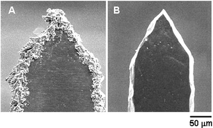
Effect of electropolishing on microneedle surface. Scanning electron micrographs of: (A) a microneedle tip with slag and debris residue remaining after cleaning with detergent powder and (B) a microneedle tip after electropolishing, resulting in removal of slag and debris, clean edges, and sharp tip.
To produce clean, smooth, and sharp microneedle surfaces, we developed an electropolishing technique to remove this slag from the microneedles. Mechanical methods like abrasive cleaning and buffing were difficult to implement without bending or otherwise damaging the microneedles. In contrast, electropolishing utilized a simple, reliable procedure that was effective to remove all of the slag and debris. This approach yielded microneedles with smooth surfaces and very sharp tips (tip radius 0.5 to 1 μm) (Fig. 2B). We believe that electropolishing was especially effective, because current density (i.e., etching rate) is largest at sites of high curvature, which inherently targets sites of surface roughness for removal [26].
Laser cutting coupled with electropolishing provides a potentially versatile method to prepare microneedles having a variety of geometries according to the pattern in which the laser is programmed to cut. To assess this versatility in the context of microneedle fabrication, we attempted to laser-cut and electropolish microneedles with increasing geometrical complexity. Using a simpler microneedle design, this process was used to create microneedles of different lengths and widths (Fig. 3A). As a more complex design, microneedles were fabricated with small through-holes (which we call ‘pockets’) of different shapes and sizes in the shafts of these microneedles (Fig. 3B). Microscopic examination showed that the inside surfaces of these pockets were smooth and clean. We believe that this is the first report of pocketed microneedles, which can provide protective cavities to transport particles into the skin, as discussed further below. As a still more complex design, we tested the ability of the process to make contoured surfaces in the form of barbs and serrated edges. Although such surfaces are more difficult to clean, debris was successfully removed with uniform cleanliness and smoothness (Fig. 3C). While these needle designs may be useful for improved microneedle retention, cutting or other effects in the skin, they are intended in this study only to demonstrate the capabilities of this fabrication process and have not been optimized for in vivo applications.
Fig. 3.
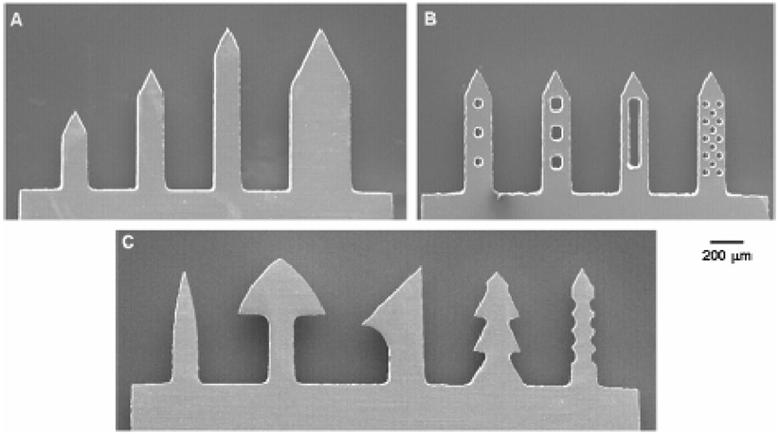
Fabrication of different microneedle geometries. Scanning electron micrographs of: (A) microneedles having different lengths and widths at a constant tip angle of 55°, (B) microneedles with ‘pockets’ of different shapes and sizes etched through the microneedle shaft, and (C) microneedles with complex geometries, such as contoured surfaces in the form of barbs and serrated edges.
In addition to fabricating individual microneedles with different shapes, the laser fabrication process was also used to fabricate two different kinds of microneedle arrays in which all needles have the same geometry: (1) in-plane microneedle rows containing microneedles oriented with their axis parallel to the sheet (Fig. 4A, a representative in-plane row with five microneedles) and (2) out-of-plane arrays with multiple rows of microneedles sticking out of the substrate with their axis perpendicular to the substrate (Fig. 4C, a representative out-of-plane array with 50 microneedles).
Fig. 4.

Different types of microneedle arrays and patches. Brightfield micrographs of: (A) an in-plane row with five microneedles, (B) a 50-microneedle patch after assembly of ten in-plane rows into slits of a foam-tape backing, (C) an out-of-plane microneedle array with 50 microneedles, and (D) a 50-microneedle patch assembled by mounting an out-of-plane array onto a foam-tape backing and then affixing a perforated, double-sided adhesive film onto the base substrate between microneedles.
3.2 Microneedle array patches
To facilitate their insertion and retention into the skin, arrays of microneedles were integrated into adhesive patches. These patches were designed to have a uniform pressure-sensitive adhesive layer on one complete side of the patch intended to contact the skin. The adhesive layer was periodically disrupted via small holes or slits to allow the microneedles to stick out for penetration. The adhesive served to hold the microneedles firmly against the skin by compensating for the mechanical mismatch between the flexible skin tissue and the rigid microneedle substrate, especially in the case of out-of-plane microneedle arrays. Microneedle arrays prepared on the basis of this design are shown for patches of in-plane microneedles (Fig. 4B) and out-of-plane microneedles (Fig. 4D).
3.3 Micro-dip coating of microneedles
Our next objective was to deposit uniform coatings on microneedle shafts. Although the conventional dip-coating process is fairly simple, it is most suitable for macroscopic coatings. Our attempts to achieve micron-scale control over coating by simply dipping and withdrawing microneedles from an aqueous solution resulted in non-uniform coatings with frequent spreading of the solution onto the base substrate. Representative brightfield images of such non-uniform coatings obtained by dipping microneedles in a 3% (w/v) aqueous solution of vitamin B are shown in Fig. 5A (single microneedle) and Fig. 5B (out-of-plane array).
Fig. 5.

Examples of poor and good microneedle coatings via brightfield micrographs of vitamin B coated microneedles. Poor, non-uniform coatings with base-substrate contamination on: (A) a single microneedle and (B) a 50-microneedle out-of-plane array. Improved coating uniformity and elimination of base-substrate contamination after addition of coating solution excipients and use of a micro-dip-coating device for (C) a single microneedle, (D) a 50-microneedle out-of-plane array, and (E) an in-plane microneedle row. Controlled length segment coverage at (E1) uncoated, (E2) 25% coated, (E3) 50% coated, (E4) 75% coated and (E5)100% coated, demonstrating spatial control of the microneedle coating process.
Based on optimized coating methods developed in other contexts [27], reduced surface tension and increased viscosity of the coating solution should improve the coating outcome by increasing the wettability of the microneedle surface and increasing the coating thickness, respectively. In addition to lowering surface tension and increasing viscosity, the ideal excipients had to meet a number of additional specifications. They needed to be water-soluble (for aqueous dipping formulations), FDA-approved as injectable excipients (for safety), solid at room temperature (to convert into a solid coating upon drying) and possess high surfactant or viscosity enhancement activity per unit mass (to minimize the excipient content and thereby maximize drug content in the dry coatings). Sodium salt of carboxymethylcellulose (low viscosity) and Lutrol F-68 NF were found to fulfill these criteria as a viscosity enhancer and surfactant, respectively. After optimization to minimize their concentration in the coating solution, these excipients were found to give uniform coatings at concentrations of 1% (w/v) carboxymethylcellulose and 0.5% (w/v) Lutrol F-68 NF using vitamin B as the model compound (Fig. 5C).
Further efforts, however, were required to address the problem of microneedle array substrate contamination with coating solution. To address this, we designed a special micro-dip-coating device that covered the dipping solution reservoir with a thin sheet containing micron-sized holes corresponding to the size and position of the microneedles in the array (Fig. 1). This physical masking eliminated solution contact with the substrate of microneedles. When properly aligned using micropositioners, only microneedles could dip through the micron-sized holes and into the coating solution, which resulted in a controlled micro-dip-coating process.
Using this design philosophy, three different coating devices were built to coat single microneedles, in-plane rows of microneedles, and out-of-plane arrays of microneedles, as described in the Materials and Methods section. These micro-dip-coating devices were able to localize coatings only to microneedle shafts for single microneedles (Fig. 5C), out-of-plane arrays (Fig. 5D) and in-plane rows (Fig. 5E) of microneedles. To further test the ability of this approach to control the length of microneedles getting coated, in-plane rows of microneedles were coated to predetermined lengths of 25%, 50%, 75% and 100% length coverage (Fig. 5E). Thus, through the combination of a suitable coating solution and coating device, highly controlled and uniform coatings can be achieved on microneedles. The approach is probably applicable to coating other microstructures as well.
Finally, it is also worth noting that the dead volume of these coating devices was 10 μl for the row-coating device, and 100 μl for the array-coating device. Therefore, only very small coating solution volumes are sufficient to coat microneedles, which is especially important when coating proteins, DNA and other expensive compounds.
3.4 Coating a large range of compounds
Our next objective was to determine how broadly this approach could be applied to coat different molecules and particles onto microneedles. To study this question, the same coating solution and coating methods were used to reproducibly coat seven different compounds onto microneedles: calcein and vitamin B (low molecular weight molecules representative of synthetic drugs), bovine serum albumin and plasmid DNA (high molecular weight biomolecules representative of protein and gene therapeutics), modified vaccinia virus (a virus particle representative of some vaccines), and latex and barium sulfate microparticles (organic and inorganic particles representative of controlled release and other particulate systems). These compounds spanned in size from small molecules (e.g., vitamin B) to micron-scale particles (e.g., 20-μm latex beads). We believe this is the first time that coating of microneedles with virus and microparticles has been studied. In all cases, coatings were reproducibly applied onto the microneedles (n=3 single microneedles for each compound). Moreover, the coatings were uniform across the entire microneedle length (representative images shown in Fig. 6).
Fig. 6.
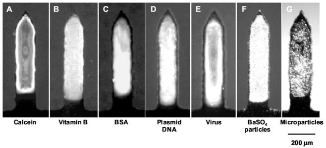
Breadth of molecules and microparticles coated onto microneedles. Fluorescent or brightfield micrographs of single microneedles coated with: (A) calcein, (B) vitamin B, (C) bovine serum albumin (BSA) conjugated with Texas Red, (D) plasmid DNA conjugated with YOYO-1, (E) modified vaccinia virus - Ankara conjugated with YOYO-1, (F) 1-μm diameter barium sulfate particles and (G) 10-μm diameter latex particles.
3.5 Dissolution times and delivery of coated molecules
To determine the dissolution time of coated molecules from microneedles, microneedles coated with vitamin B (Fig. 7A-before) were inserted into porcine cadaver skin. Removal from skin 10-s after insertion showed that most of the coating was removed (data not shown) and 20 s after insertion the microneedle coating was completely removed (Fig. 7A-after).
Fig. 7.
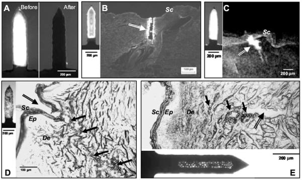
In vitro dissolution and delivery from coated microneedles. (A) Single microneedle coated with vitamin B before and after a 20 s insertion into porcine cadaver skin imaged by fluorescence microscopy. The absence of fluorescence in the image after insertion indicates complete dissolution of the coating in the skin. (B) Histological section of porcine cadaver skin after inserting a calcein-coated microneedle (inset on left) and (C) X-ray micrograph of intact porcine cadaver skin after inserting a barium sulfate-coated microneedle (inset on left). The arrows in (B) and (C) point to the microneedle insertion sites and the bright regions represent calcein and barium sulfate delivery into the skin. The absence of fluorescence on top of the skin suggests that the coating did not wipe off during insertion. (D) Histological section of porcine cadaver skin after inserting a microneedle coated with 10-μm diameter beads (inset on left) and (E) histological section of porcine cadaver skin after inserting a ‘pocketed’ microneedle containing 20-μm diameter beads (inset at bottom). In (D) and (E), the double lined arrows point to the microneedle insertion sites, while the solid black arrows point to some of the beads delivered into the skin, which appear as tiny circles. The absence of beads on the skin surface indicates that beads did not wipe off during insertion. Sc = Stratum Corneum, Ep = Epidermis, De = Dermis.
To determine if microneedle coatings were being delivered into the skin, as opposed to, for example, flaking off onto the skin surface, calcein-coated microneedles were inserted into porcine cadaver skin. After removing the microneedles and examining the skin surface, no calcein coating residue was observed (data not shown). Examination of histological sections of the skin revealed deposition of calcein along the shaft of the insertion path within the skin (Fig. 7B). Together these observations suggest that calcein coated onto microneedles was delivered into the skin without wiping off on the skin surface. Similar results were also observed for sulforhodamine-coated microneedles (data not shown), suggesting that the results are more generally applicable to different molecules.
To further quantify the delivery efficiency of coated microneedles, rows of microneedles coated with vitamin B were inserted into pig cadaver skin. A total mass of 7.86 ± 0.3 μg of vitamin B was originally coated on these microneedles. After a 5-min insertion of these microneedles into skin, 7.18 ± 0.4 μg (91.4 ± 6 %) of the vitamin B was delivered into the skin, whereas 0.17 ± 0.1 μg (2.1 ± 1 %) was found on the skin surface and 0.51 ± 0.2 μg (6.5 ± 2 %) remained adhered to the microneedle surface after removal from the skin. We conclude that these coatings were able to remain adherent during insertion into the skin and then efficiently dissolve off the microneedles within the skin for delivery of greater than 90% of the coated vitamin B.
3.6 Delivery of microparticles
It was also of interest to deliver microparticles into the skin, which has not been addressed in previous studies. Delivery of microparticles is challenging, because larger microparticles are more likely to wipe off onto the skin surface during insertion into the skin. To prevent microparticle coatings from wiping off, we hypothesized that faster insertion (momentum) and seclusion of microparticles within protective cavities in the form of holes or ‘pockets’ in the microneedles would facilitate carrying microparticles into the skin. To test this hypothesis, we coated microneedles with particles having three different diameters: 1-μm diameter barium sulfate particles, and 10- and 20-μm diameter latex beads. After insertion into porcine cadaver skin at slow speed (0.5 to 1 mm/s), only barium sulfate particles were successfully delivered into porcine skin without wiping off onto the skin surface (Fig. 7C).
At higher insertion speed (1 to 2 cm/s), the momentum of the microneedles was able to carry the coating of 10-μm diameter particles into the skin (Fig. 7D); however, 20-μm diameter beads were still found predominantly as residue on the skin surface (data not shown). The 20-μm diameter latex particles were successfully delivered into the skin after loading them into the protective cavity of a pocket within the microneedle shaft and delivering at 1 to 2 cm/s (Fig. 7E). Therefore, by using appropriate microneedle design and insertion methods, even relatively large microparticles can be delivered into the skin using coated microneedles.
3.7 Delivery from a microneedle array patch
To evaluate the performance of microneedle arrays assembled in a patch (Fig. 4), coated microneedle patches were inserted into human cadaver skin and non-coated microneedles were inserted into the skin of human subjects. After inserting and removing microneedles coated with Trypan Blue from cadaver skin, surface examination of the treated skin showed an array of blue dots corresponding to sites of microneedle penetration and coating deposition from the array (Fig. 8A). No residue was observed on the skin surface indicating delivery of coatings into the skin.
Fig. 8.

In vitro and in vivo performance of microneedle patches in human skin. (A) Surface view of human cadaver skin imaged by brightfield microscopy after inserting a 50-microneedle patch dip-coated with trypan blue dye. The 50 dark spots correspond to sites of trypan blue coating delivered and dissolved in the skin from the 50 microneedles in the patch. (B) Skin from the forearm of a human subjected imaged by brightfield microscopy after inserting a microneedle patch containing 50 microneedles and subsequently applying gentian violet to stain the sites of microneedle insertion, which demonstrates microneedle penetration into the skin.
Although we did not prepare coated microneedles suitable for human use, we did want to evaluate the performance of microneedle patches in human subjects. Out-of-plane arrays containing 50 uncoated microneedles were inserted and removed from the forearms of humans subjects. To determine if microneedles inserted, a solution of gentian violet was applied to the skin to stain sites of microneedle insertion. Complete microneedle insertion was obtained (n=3 subjects, Fig. 8B). The subjects reported that insertion of the arrays did not cause discomfort.
4. Discussion
This study showed that micro-dip coating provides a versatile technique to coat microneedles with a wide variety of molecules including small synthetic compounds, proteins and DNA. We have also reported for the first time that viruses and a variety of microparticles can be coated onto microneedles. This coating method uses aqueous formulations with FDA-approved excipients at room temperature. Histological examination of skin after insertion of coated microneedles showed successful delivery into the skin within seconds. This detailed study of the microneedle coating process and its breadth of applicability serves to compliment previous studies demonstrating delivery of peptides and proteins to the skin using coated microneedles [14, 23, 28].
4.1 Microneedle fabrication methods
This study presented fabrication methods to produce microneedles suitable for coating. Although the laser-cutting method could be used with a variety of different metals and other materials, this study employed stainless steel, which is used in many FDA-approved medical devices and is inexpensive. Microneedles were fabricated to have a variety of different geometries. For the first time, we have reported the fabrication of ‘pocketed’ microneedles (Fig. 3B). Pockets provide a protective cavity within the microneedle shaft and were used to deliver particles up to 20-μm in diameter into the skin without wiping off during insertion.
Microneedles with other complex geometries, such as contoured surfaces in the form of barbs and serrated edges, were fabricated and polished to have clean edges and sharp tips (Fig. 3C). Some of these shapes can be used to help anchor microneedles within the skin for improved insertion and retention [14, 23]; however, they may cause skin damage or pain upon withdrawal. Microneedles of different lengths and widths (Fig. 3A) can be fabricated using this method.
Using a bench-scale apparatus, finished microneedle arrays were cut and polished at a rate of two 50-needle arrays per hour. For large-scale manufacturing, this rate can easily be increased by orders of magnitude by using higher power lasers that can cut more quickly and can be beam-split to cut multiple arrays in parallel using fully automated processes. Use of multiple lasers can increase throughput still further through parallel processing. Likewise, larger and multiple electropolishing baths can increase polishing rates. Finally, the manual process using in this study to bend microneedles for out-of-plane arrays can also be easily automated for mass production.
4.2 Microneedle coating methods
The success of coated microneedles for drug delivery depends on the ability to reliably coat a controlled drug layer onto microneedles. Our initial attempts to coat microneedles by dipping into an aqueous drug solution resulted in patchy to no surface coverage (Fig. 5A). To overcome this difficulty, we formulated a coating solution with increased viscosity and reduced surface tension containing 1% carboxymethylcellulose and 0.5% Lutrol F-68 NF as viscosity enhancer and surfactant, respectively. This enabled complete and uniform coverage of the dipped microneedle surface (Fig. 5). This coating formulation was shown to be very versatile. Small molecules, macromolecules and microparticles were all applied as uniform coatings (Fig. 6). The two excipients used to modify the dipping solution have already been approved by the FDA as excipients in injectable formulations, so this coating formulation should also be safe for use in humans.
Another important component of the micro-dip-coating process is the dip-coating device. Simply dipping microneedles into a small beaker containing dipping solution often resulted in contamination of the microneedle substrate (Fig. 5B). Capillary forces are mainly responsible for the rise of the free meniscus along the microneedle shaft to eventually touch the base substrate. This effect is amplified in an array due to the close spacing of the microneedles, which enhances the capillary effect and can lead to bridging of coating solution between adjacent microneedles.
To address these issues, we have developed a dip-coating design that uses dip holes with dimensions similar to that of individual microneedles instead of a large, open coating surface to prevent the meniscus rise and to physically mask the base substrate between microneedles. This design philosophy was incorporated into three different micro-dip-coating devices to coat single microneedles, in-plane rows, and out-of-plane microneedle arrays. Micropositioners were also incorporated into the dipping devices to align microneedles with dip holes. Using these micro-dip-coating devices, coating deposition can be highly controlled to localize only on microneedles and, when desirable, to coat only portions along the shaft of microneedles in a reproducible manner (Fig. 5E). In the context of this and other on-going studies, this coating method has been used by us to reliably and reproducibly prepare many hundreds of microneedle devices for in vitro and in vivo drug and vaccine delivery studies.
Concerning the practical use of micro-dip-coating, the devices developed for this study (Fig. 1) require very small volumes of coating solution, ranging from 10 μl for single microneedles to 100 μl for 50-needle, out-of-plane arrays. The ability to use small reservoirs of coating solution is important, because many experimental and established biotherapeutics are expensive and available only in limited quantity. Another practical issue is that air bubbles were sometimes formed in the dip-coating device, which interfered with the coating process. To prevent this, vent holes were incorporated into the design to release air (Fig. 1). While coating large numbers of microneedle devices, evaporation of coating solution from the dipping reservoir sometimes left behind solid deposits that could block the dip-coating holes. To prevent this, the syringe used to fill the dipping reservoir was manually pulsated to mix the coating solution.
4.3 Delivery from coated microneedles
Delivery from coated microneedles was found to be efficient, where the vast majority of coated drug was deposited in the skin and essentially no residue was found on the skin surface, which suggests high bioavailability. Although efficient, the total amount of drug that can be delivered is constrained by the relatively small surface area of microneedles. Using vitamin B as a model drug, we were able to coat up to 2.6 μg of drug per microneedle (750 μm long and 200 μm wide, data not shown). Based on a maximum array size of a few hundred microneedles, we can conclude that hundreds of micrograms up to perhaps 1 mg of drug can be coated onto an array. Therefore, coated microneedles are most suitable for potent drugs, such as therapeutic proteins, DNA and vaccines. Vaccine delivery using coated microneedles is especially attractive, because microneedle-based delivery to the skin can target dendritic cells residing in the epidermis for a more potent immune response. Further, storage and delivery of vaccine in solid-state coatings should increase antigen stability, which may help eliminate the need for cold-chain storage.
5.Conclusion
Motivated by previous results demonstrating coated microneedles to deliver drugs and vaccines to the skin, here we sought to carry out a detailed study examining coating methods and their breadth of applicability. Using laser cutting followed by electropolishing, stainless steel microneedles of different geometries and configurations were fabricated with sharp tips and clean edges suitable for coating. To facilitate insertion and adhesion to the skin, microneedle patches were developed with pressure-sensitive adhesive surrounding the base of the microneedles.
A novel micro-dip-coating apparatus was designed to control surface tension-driven wicking of coating solution up microneedle shafts and onto the base substrate. A coating formulation was also developed to achieve uniform coating solution deposition on microneedles by using low concentrations of carboxymethylcellulose and Lutrol F-68 NF as excipients to increase viscosity and decrease surface tension, respectively. Using this approach, single microneedles, in-plane rows of microneedles, and out-of-plane arrays of microneedles were coated without contaminating the base and with micron-scale control over the length of the microneedle shaft to be coated. For the first time, organic and inorganic microparticles as well as viruses were coated onto microneedles, in addition to vitamin B, calcein, bovine serum albumin, and plasmid DNA.
Microneedle coatings dissolved within seconds after insertion into cadaver skin. Successful delivery into skin was achieved from microneedles surface coated with molecules as well as microparticles up to 10 μm in diameter. Using novel ‘pocketed’ microneedles to mechanically protect coatings during insertion, 20-μm diameter particles were delivered into skin without wiping off onto the skin surface. Integrated patches containing 50-microneedle arrays were also shown to insert into the skin of human subjects and to deliver their coated payload into human cadaver skin. Altogether, this study provides versatile microneedle fabrication and controlled micro-dip-coating methods that enable coating of microneedles using a mild process with FDA-approved excipients with a wide variety of molecules and microparticles for delivery to the skin.
Acknowledgment
We would like to thank Dr. Mark Allen for use of the IR and CO2 lasers in his lab; Richard Shafer, Dr. Shawn Davis, and Ed Birdsell for helpful discussions regarding laser operation; Dr. Jung-Hwan Park for additional helpful discussions; Dr. David Garber (Emory Vaccine Center) for providing the modified vaccinia virus; and Dannae Rowe (MACtac Technical Products) for providing the medical foam tapes used in the microneedle patch fabrication. Mark Prausnitz is the Emerson Lewis Faculty Fellow. This work was supported in part by the National Institutes of Health and took place in the Center for Drug Design, Development and Delivery and the Institute for Bioengineering and Bioscience at the Georgia Institute of Technology.
Footnotes
Publisher's Disclaimer: This is a PDF file of an unedited manuscript that has been accepted for publication. As a service to our customers we are providing this early version of the manuscript. The manuscript will undergo copyediting, typesetting, and review of the resulting proof before it is published in its final citable form. Please note that during the production process errors may be discovered which could affect the content, and all legal disclaimers that apply to the journal pertain.
References
- [1].Walsh G. Biopharmaceuticals: recent approvals and likely directions. Trends Biotechnol. 2005;23(11):553–558. doi: 10.1016/j.tibtech.2005.07.005. [DOI] [PubMed] [Google Scholar]
- [2].Nir Y, Paz A, Sabo E, Potasman I. Fear of injections in young adults: prevalence and associations. Am J Trop Med Hyg. 2003;68(3):341–344. [PubMed] [Google Scholar]
- [3].Simonsen L, Kane A, Lloyd J, Zaffran M, Kane M. Unsafe injections in the developing world and transmission of bloodborne pathogens: a review. Bull World Health Organ. 1999;77(10):789–800. [PMC free article] [PubMed] [Google Scholar]
- [4].Orive G, Hernandez RM, Rodriguez Gascon A, Dominguez-Gil A, Pedraz JL. Drug delivery in biotechnology: present and future. Curr Opin Biotechnol. 2003;14(6):659–664. doi: 10.1016/j.copbio.2003.10.007. [DOI] [PubMed] [Google Scholar]
- [5].Prausnitz MR, Mitragotri S, Langer R. Current status and future potential of transdermal drug delivery. Nat Rev Drug Discov. 2004;3(2):115–124. doi: 10.1038/nrd1304. [DOI] [PubMed] [Google Scholar]
- [6].Barry BW. Breaching the skin′s barrier to drugs. Nat Biotech. 2004;22(2):165–167. doi: 10.1038/nbt0204-165. [DOI] [PubMed] [Google Scholar]
- [7].Prausnitz MR. Microneedles for transdermal drug delivery. Adv Drug Deliv Rev. 2004;56(5):581–587. doi: 10.1016/j.addr.2003.10.023. [DOI] [PubMed] [Google Scholar]
- [8].Prausnitz M, Mikszta J, Raeder-Devens J. In: Percutaneous Penetration Enhancers. Smith E, Maibach H, editors. CRC Press; Boca Raton, FL: 2005. pp. 239–255. [Google Scholar]
- [9].Kaushik S, Hord AH, Denson DD, McAllister DV, Smitra S, Allen MG, Prausnitz MR. Lack of pain associated with microfabricated microneedles. Anesth Analg. 2001;92(2):502–504. doi: 10.1097/00000539-200102000-00041. [DOI] [PubMed] [Google Scholar]
- [10].Mikszta JA, Alarcon JB, Brittingham JM, Sutter DE, Pettis RJ, Harvey NG. Improved genetic immunization via micromechanical disruption of skin-barrier function and targeted epidermal delivery. Nat Med. 2002;8(4):415–419. doi: 10.1038/nm0402-415. [DOI] [PubMed] [Google Scholar]
- [11].Henry S, McAllister DV, Allen MG, Prausnitz MR. Microfabricated microneedles: a novel approach to transdermal drug delivery. J Pharm Sci. 1998;87(8):922–925. doi: 10.1021/js980042+. [DOI] [PubMed] [Google Scholar]
- [12].McAllister DV, Wang PM, Davis SP, Park JH, Canatella PJ, Allen MG, Prausnitz MR. Microfabricated needles for transdermal delivery of macromolecules and nanoparticles: fabrication methods and transport studies. Proc Natl Acad Sci U S A. 2003;100(24):13755–13760. doi: 10.1073/pnas.2331316100. [DOI] [PMC free article] [PubMed] [Google Scholar]
- [13].Martanto W, Davis SP, Holiday NR, Wang J, Gill HS, Prausnitz MR. Transdermal delivery of insulin using microneedles in vivo. Pharm Res. 2004;21(6):947–952. doi: 10.1023/b:pham.0000029282.44140.2e. [DOI] [PubMed] [Google Scholar]
- [14].Cormier M, Johnson B, Ameri M, Nyam K, Libiran L, Zhang DD, Daddona P. Transdermal delivery of desmopressin using a coated microneedle array patch system. J Control Release. 2004;97(3):503–511. doi: 10.1016/j.jconrel.2004.04.003. [DOI] [PubMed] [Google Scholar]
- [15].Lin W, Cormier M, Samiee A, Griffin A, Johnson B, Teng CL, Hardee GE, Daddona PE. Transdermal delivery of antisense oligonucleotides with microprojection patch (Macroflux) technology. Pharm Res. 2001;18(12):1789–1793. doi: 10.1023/a:1013395102049. [DOI] [PubMed] [Google Scholar]
- [16].Chabri F, Bouris K, Jones T, Barrow D, Hann A, Allender C, Brain K, Birchall J. Microfabricated silicon microneedles for nonviral cutaneous gene delivery. Br J Dermatol. 2004;150(5):869–877. doi: 10.1111/j.1365-2133.2004.05921.x. [DOI] [PubMed] [Google Scholar]
- [17].Mikszta JA, Sullivan VJ, Dean C, Waterston AM, Alarcon JB, Dekker JP, 3rd, Brittingham JM, Huang J, Hwang CR, Ferriter M, Jiang G, Mar K, Saikh KU, Stiles BG, Roy CJ, Ulrich RG, Harvey NG. Protective immunization against inhalational anthrax: a comparison of minimally invasive delivery platforms. J Infect Dis. 2005;191(2):278–288. doi: 10.1086/426865. [DOI] [PubMed] [Google Scholar]
- [18].Dean CH, Alarcon JB, Waterston AM, Draper K, Early R, Guirakhoo F, Monath TP, Mikszta JA. Cutaneous Delivery of a Live, Attenuated Chimeric Flavivirus Vaccines against Japanese Encephalitis (ChimeriVaxTM-JE) in Non-Human Primates. Human Vaccines. 2005;1(3):106–111. doi: 10.4161/hv.1.3.1797. [DOI] [PubMed] [Google Scholar]
- [19].Reed ML, Lyev W-K. Microsystems for drug and gene delivery. Proc IEEE. 2004;92(1):56–75. [Google Scholar]
- [20].Park JH, Allen MG, Prausnitz MR. Polymer microneedles for controlled-release drug delivery. Pharm Res. 2006;23(5):1008–1019. doi: 10.1007/s11095-006-0028-9. [DOI] [PubMed] [Google Scholar]
- [21].Zahn JD, Talbot NH, Liepmann D, Pisano AP. Microfabricated polysilicon microneedles for minimally invasive biomedical devices. Biomed Microdevices. 2000;2:295–303. [Google Scholar]
- [22].Babiuk S, Baca-Estrada M, Babiuk LA, Ewen C, Foldvari M. Cutaneous vaccination: the skin as an immunologically active tissue and the challenge of antigen delivery. J Control Release. 2000;66(23):199–214. doi: 10.1016/s0168-3659(99)00274-6. [DOI] [PubMed] [Google Scholar]
- [23].Matriano JA, Cormier M, Johnson J, Young WA, Buttery M, Nyam K, Daddona PE. Macroflux microprojection array patch technology: a new and efficient approach for intracutaneous immunization. Pharm Res. 2002;19(1):63–70. doi: 10.1023/a:1013607400040. [DOI] [PubMed] [Google Scholar]
- [24].Bierwagen GP. Film coating technologies and adhesion. Electrochim Acta. 1992;37(9):1471–1478. [Google Scholar]
- [25].Beebe DJ, Mensing GA, Walker GM. Physics and applications of microfluidics in biology. Annu Rev Biomed Eng. 2002;4(1):261–286. doi: 10.1146/annurev.bioeng.4.112601.125916. [DOI] [PubMed] [Google Scholar]
- [26].Landolt D. Fundamental aspects of electropolishing. Electrochim Acta. 1987;32(1):1–11. [Google Scholar]
- [27].Schunk PR, Hurd AJ, Brinker CJ. In: Liquid film coating : scientific principles and their technological implications. Kistler SF, Schweizer PM, editors. Chapman & Hall; London: 1997. pp. 673–708. [Google Scholar]
- [28].Widera G, Johnson J, Kim L, Libiran L, Nyam K, Daddona PE, Cormier M. Effect of delivery parameters on immunization to ovalbumin following intracutaneous administration by a coated microneedle array patch system. Vaccine. 2005 doi: 10.1016/j.vaccine.2005.09.049. [DOI] [PubMed] [Google Scholar]