

Abstract
Background/aims
The three dimensional (3‐D) visualisation of the optic disc in true colour will give essential meaning in clinical application. It is not only useful for clinicians in the evaluation of the condition of the optic disc, but it also simplifies the pathological diagnosis and disease progression monitoring. This paper describes a complete 3‐D optic disc reconstruction method from a pair of stereo images by a series of robust procedures including camera calibration, image registration, depth recovery, and ocular media optical inclusion.
Methods
Two registration techniques (correlation and feature based methods) are combined together to prune the uncertain matching points in order to improve the overall accuracy of registration. The ocular media within the eyeball are lump modelled as a single lens and integrated into the reconstruction process to obtain an accurate 3‐D optic disc image.
Conclusion
The recovered 3‐D optic disc images show good consistency and compatibility when compared with the results from Heidelberg retina tomography (HRT) under clinical validation, with an additional advantage of implementing a more economical and conventional mode of retinal image acquisition.
Keywords: optic disc reconstruction, image registration, ocular‐media optical modelling, stereo fundus image, glaucoma
The optic disc is one of the main components on the retina. Having the three dimensional (3‐D) visualisation of the optic disc in true colour will not only provide clinicians a clear and direct view of retinal structure, but it can also make significant improvements in the accuracy of optic disc feature extraction and evaluation. According to Masunori1 the cup is defined as the bright area at the optic disc centre with a certain depth down from the optic disc boundary. Quantitative measurement of the cupping of the optic disc is generally used to evaluate the progress of glaucoma. The existing ophthalmic instrument used to measure 3‐D depth information, such as optical coherence tomography (OCT), only gives a profile image at a certain cross section. The full 3‐D image and true colour information cannot be obtained from OCT. Another effective instrument, the Heidelberg retina tomograph (HRT), which is based on a scanning laser technique, cannot provide a true colour 3‐D visualisation. The two dimensional (2‐D) colour fundus image is still referred to by most clinicians for the estimation of disc and cup boundaries from the 3‐D HRT image. Hence, a computer aided reconstruction of a true colour 3‐D optic disc is clinically significant.
The common 3‐D reconstruction technique from stereo images does not work well because the optic disc is observed through both the eye lens and camera lenses in imaging process. Hence, the prime problems to be solved in 3‐D optic disc reconstruction are camera calibration, image registration, depth recovery, and ocular media optical estimation. So far only a few researchers have focused their work on full 3‐D optic disc reconstruction. Deguchi et al2 described a full retinal surface reconstruction approach, where the optical effect inside the eye was considered to optimise a spherical retina model. However, the spherical model of retinal surface could not sufficiently display some abnormal features, thus it might not be adequate for diagnosis. A number of techniques of image registration have been proposed not only for fundus images but also in other applications, where the depth value can be computed from the detected disparity. Brown et al3 and Scharstein and Szelisky4 reviewed the current approaches of stereo matching and classified them as the local method and the global method. In the local method, the disparity computation at a given point depends only on the similarity inside a comparing window through the measurements based on correlation,5 absolute difference, rank transform, power cepstrum,6 optical flow, phase, features,7 mutual information,8 and so on. To obtain more reliable results, constraints or information from surrounding matching points are generally introduced into local matching methods as described by Zhang et al5and Wang et al.7 Global methods estimate the disparity by minimising a global cost function defined based on both similarity and smoothness. In work by Can et al,9 Stoyanov et al,10 and Veeser et al11 the global minimising function is varied and iteratively optimised to improve the matching accuracy. Some methods of fundus image registration make use of the sparse bifurcations of blood vessels to globally estimate a defined transformation model.8,9,12,13 The objective of these projects was to fuse multiple fundus images to a single wide angle image. Hence, the variation of depth was ignored when setting up the transformation model. In 3‐D reconstruction, estimating depth information is the main objective; hence, the registration of two images cannot be simplified as the optimisation of a certain transformation model.
A full 3‐D optic disc reconstruction approach is proposed in this paper. A fast and robust dual registration method is introduced to precisely extract correspondences. Ocular media within the eyeball is included by modelling as a single lens. A new method is proposed to calibrate and integrate this effect into the reconstruction process to provide a real 3‐D image of optic disc.
Methodology
Principle of 3‐D reconstruction from stereo images
Figure 1 shows the optical model of the eye and fundus camera where the imaging process can be separated into two steps. If the complex ocular structure consisting of cornea, eye lens, vitreous, and aqueous, etc, is lump modelled as a single and simple lens with focal length fe, the real retinal surface will be mapped into an image called virtual surface through the modelled eye lens. The virtual surface is then projected onto the image sensor through camera lenses to create a pair of stereo images. Hence, in this paper, the virtual surface is first recovered by dual registration and then the ocular media optical characteristics are integrated into the reconstruction process to obtain the real 3‐D optic disc image.

Figure 1 Optical model of the eye and stereo fundus camera (adapted from Deguchi2).
According to Saine and Tyler,14 the special structure of the stereo fundus camera has a parallel stereo configuration as shown in figure 2. The object point M(x,y,z), expressed according to origin O, is projected onto the left image at mL(uL,νL) and then right image at mR(uR,νR), both of which are located on the same horizontal scan line. Let (uL,νL) and (uR,νR) indicate the row and column numbers in the left image and right image respectively. Then mL(uL,νL) and mR(uR,νR) are called corresponding points or matching points. The depth is inversely proportional to the disparity between each matching pair:15

Figure 2 Parallel stereo image system.
 |
where f is the focal length of the two cameras, the term (νL−νR) is disparity, b is the baseline which is the distance between two camera centres. The units of b, f, z, (νL−νR) are all in pixels. Focal length is measured to be 2478.0 pixels by the planar object based camera calibration method described by Zhang.16 Based on the fundus camera design, its baseline is found to be fixed at 3 mm. Therefore, the essential parts for reconstruction are image registration and ocular media optical estimation.
Dual registration and depth recovery
Constraint based dual registration, proposed by Xu and Chutatape,17 is applied to detect subpixel matching points and then converted into dense depths, which will be briefly introduced shortly afterwards. Let mL be the reference point in the left image; the points in the right image on the same horizontal scan line are the candidate correspondence points denoted as mR. Two operations, correlation method and feature based method, are employed to detect the best matching points, and the resulted matching points are then compared.
In the correlation method, the candidate point with maximum correlation is the best matching point. The normalised cross correlation between two points is
 |
where f and g are the intensity values of left and right images, f ¯ and g ¯ are the average intensity value in the comparing windows, and (2W + 1) is the comparing window size.
In the feature based method, three features are extracted in each comparing window. They are intensity value, x gradient magnitude, and gradient orientation. The average absolute differences of these features between two windows are computed and combined as error defined as
The point that has the minimal error is considered to be the best matching point.
For each reference point in the left image, two best matching points in the right image can be detected based on two operations. Polynomial fitting is used to obtain subpixel matching in both operations. If the difference of the locations of these two matching points is less than a threshold, which is set to be one pixel in this paper, the average location is the final corresponding point. Otherwise, there is no suitable corresponding point to the reference point. Then, the next point is selected from the reference image and the operation is repeated until all the corresponding points are measured. Finally, a piecewise cubic interpolation and median filter is applied to obtain the continuous depth based on equation (1). Figure 3 displays the basic steps of the proposed method.

Figure 3 The main procedure of dual registration and dense depth recovery.
Calibration of the optical effect of the eye
The 3‐D depth image recovered from stereo fundus images by dual registration (see above) is the virtual surface as appeared through the eye lens as shown in figure 1, where Oe and fe are the optical centre and focal length of the modelled single eye lens, respectively. A calibration method is proposed here to extract the real depths of retina from the virtual surface as follows. Let M(x, y, z) computed above and M(X, Y, Z) in figure 1 denote the same point on the virtual surface according to the origin O and Oe, respectively. Let Mr(Xr, Yr, Zr) be the certain point on the real retinal surface according to the origin Oe, with the corresponding point on the virtual surface denoted by M(X, Y, Z), where Zr and Z are both positive numbers for computational convenience. Consequently we have
 |
Assume that there is a reference plane perpendicular to the optical axis and located at Zr0; the corresponding image of this reference plane appears at Z0. The absolute positions of Zr0 and Z0 need not be known. The relative depth in virtual surface is then
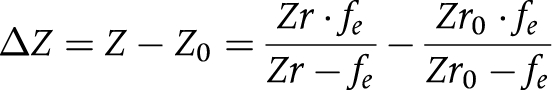 |
From this equation, the relation between the relative depth of real retinal surface ΔZr and the relative depth of virtual image ΔZ can be set up as
 |
Given Zr0 and fe, the depth of real retinal surface can be estimated from the recovered 3‐D virtual surface with respect to the reference plane. We assume that the focal length of the eye fe is fixed. One example of focal length fe is reported to be 17.05 mm (58.64 dioptres).18
The maximal cup depth to be used to calibrate Zr0 is defined to be the relative depth from the periphery of retinal surface to the lowest region of optic disc. A circle of 2.5 mm diameter is drawn at the periphery of optic disc to define the reference plane used to measure the maximal cup depth as shown in figure 4. The maximum cup depth ΔZr as measured from HRT and belonging to a certain pixel will have the corresponding maximum cup depth ΔZ under the same definition from the recovered 3‐D virtual surface computed as a result (see above). Given N pairs of ΔZ and ΔZr measured from N stereo image pairs and their corresponding HRT images, then Zr0 can be estimated from

Figure 4 Cross section of the optic disc.
 |
After Zr0 is estimated, the depths of real 3‐D retinal surface can be approximately recovered from equation (6) based on the reference plane as shown in figure 4.
Results and discussions
Calibration of Zr0
Eight pairs of images were selected to calibrate Zr0, which was based on the criteria of high quality in stereo fundus images and low noise in HRT images. The maximum cup depths, ΔZr and ΔZ, measured from HRT and their corresponding values from 3‐D virtual surface are given in table 1. ΔZ is negative here because it is expressed according to the optical centre Oe. The Zr0 was measured to be 20.14 mm from equation (7). Hence, for every 3‐D image (virtual surface) computed, the 3‐D image with true depths can be approximately obtained from equation (6).
Table 1 Maximal cup depths from HRT and 3‐D virtual image.
| No | ΔZr from HRT (mm) | ΔZ from virtual surface (mm) | No | ΔZr from HRT (mm) | ΔZ from virtual surface (mm) |
|---|---|---|---|---|---|
| 1 | 0.55 | −12.88 | 5 | 0.70 | −16.49 |
| 2 | 0.46 | −9.33 | 6 | 1.23 | −19.52 |
| 3 | 0.76 | −20.92 | 7 | 0.66 | −17.44 |
| 4 | 1.10 | −16.60 | 8 | 0.95 | −26.18 |
3‐D optic disc reconstruction
Twenty five pairs of stereo images of the abnormal optic disc (256×272 pixels) provided by the National University Hospital were tested by the proposed 3‐D reconstruction method and then compared with HRT results. A pair of stereo RGB optic disc images is illustrated as an example in figure 5. The virtual depths were estimated by the dual registration method as shown in figure 6. Pure feature based method and pure correlation method were both applied on the image pair to detect the correspondences and then converted to the depths. The results are given in figure 6A and B, respectively. It can be observed that some matching points were incorrectly identified by each individual method, whereas the proposed dual registration method could effectively drop these uncertain matching points as shown in figure 6C. The virtual depths were then modified to obtain the real depths based on equation (6). The final recovered 3‐D optic disc image is shown in figure 7A, with corresponding 3‐D image measured from HRT as illustrated in figure 7B. Through observation, the 3‐D shapes from the two sources are comparable, although the one estimated from the stereo image pair may appear to have larger noise variance.

Figure 5 A pair of stereo images.

Figure 6 An example of dual registration. (A) Sparse depths from pure feature based method, (B) sparse depths from pure correlation method, (C) final sparse depths from proposed dual registration method.

Figure 7 Recovered 3‐D images of optic disc. (A) 3‐D optic disc image from proposed method. (B) 3‐D optic disc image from HRT.
Evaluation
Based on the 3‐D image, the cup and disc contours can be estimated. The cup to disc (C/D) vertical ratio is not only a disc parameter for analysis, but also for evaluating the reconstruction results. The computer generated cup and disc contours19 were compared with the results from HRT and an experienced ophthalmologist as shown in figure 8, where the disc contour was detected by the deformable model technique described by Xu and Chutatape,19 and the cup was segmented by the similar technique with the varied energy function based on the depth information20,21 of one third drop from the disc edge. The contours estimated by the ophthalmologist were set to be the ground truth. The C/D vertical ratios were measured to be 0.62, 0.57, and 0.71 from the proposed method, HRT, and the ophthalmologist respectively. Since the automated estimation of the cup contour is still a challenging work, it can be noticed that the cup contours are not exactly the same as the ground truth, but both have a similar shape. The C/D vertical ratios of 25 testing images were computed and given in table 2. The correlations of the results with ground truth are 0.71 and 0.67, respectively for the proposed method and HRT. These values imply that both methods of 3‐D optic disc reconstruction give comparable results.

Figure 8 Cup and disc contours extracted from 3‐D optic disc image. (A) Proposed method, (B) HRT, (C) ophthalmologist.
Table 2 Cup to disc vertical ratio.
| No | Proposed method | HRT | Ophthalmologist |
|---|---|---|---|
| 1 | 0.59 | 0.58 | 0.54 |
| 2 | 0.49 | 0.66 | 0.72 |
| 3 | 0.65 | 0.63 | 0.66 |
| 4 | 0.56 | 0.61 | 0.67 |
| 5 | 0.64 | 0.45 | 0.52 |
| 6 | 0.66 | 0.46 | 0.69 |
| 7 | 0.82 | 0.94 | 0.85 |
| 8 | 0.70 | 0.21 | 0.76 |
| 9 | 0.68 | 0.82 | 0.78 |
| 10 | 0.73 | 0.79 | 0.77 |
| 11 | 0.59 | 0.41 | 0.48 |
| 12 | 0.47 | 0.37 | 0.52 |
| 13 | 0.45 | 0.27 | 0.44 |
| 14 | 0.43 | 0.46 | 0.52 |
| 15 | 0.70 | 0.47 | 0.65 |
| 16 | 0.61 | 0.69 | 0.70 |
| 17 | 0.78 | 0.88 | 0.82 |
| 18 | 0.70 | 0.86 | 0.65 |
| 19 | 0.61 | 0.76 | 0.72 |
| 20 | 0.71 | 0.78 | 0.76 |
| 21 | 0.58 | 0.60 | 0.68 |
| 22 | 0.66 | 0.58 | 0.62 |
| 23 | 0.62 | 0.58 | 0.72 |
| 24 | 0.67 | 0.56 | 0.68 |
| 25 | 0.62 | 0.57 | 0.71 |
| Corr | 0.71 | 0.67 | – |
Corr, correlation.
Conclusion
A full 3‐D optic disc reconstruction approach is proposed in this paper, including dual registration, dense depth recovery, and ocular media optical integration. The combined correlation and feature based methods can effectively help prune the uncertain correspondences and obtain more accurate disparities, which are then converted into virtual 3‐D retinal image. The real depths are obtained by modelling the ocular media as a single lens and then calibrated by using the maximum cup depth from HRT results. The experimental results show that the proposed method can recover the 3‐D shape of the optic disc successfully. Compared with HRT results, the recovered 3‐D images give comparable clinical results which can provide clinicians with a direct view of the true colour 3‐D optic disc. It also allows them to have an economical and simpler imaging modality to observe and monitor the variation of 3‐D optic disc shape for diagnosis.
Abbreviations
2‐D - two dimensional
3‐D - three dimensional
HRT - Heidelberg retina tomography
OCT - optical coherence tomography
References
- 1.Masunori K, Manabu N, Tsuguo N. A method for analyzing a stereoscopic image of a fundus, and an apparatus for executing that method. Patent no EP0846439 1998
- 2.Deguchi K, Kawamata D, Mizutani K.et al 3D fundus shape reconstruction an display from stereo fundus images. IEICE Trans Inf Syst 2000. E83‐D(no 7)
- 3.Brown M. Z, Burschka D, Hager GD. Advances in computational stereo. IEEE Transactions on Pattern Analysis and Machine Intelligence 200325993–1008. [Google Scholar]
- 4.Scharstein D, Szelisky R. A taxomomy and evaluation of dense two‐frame stereo correspondence algorithms. The International Journal of Computer Vision 2002477–42. [Google Scholar]
- 5.Zhang Z, Deriche R, Faugeras O.et al A robust technique for matching two uncalibrated images through the recovery of the unknown epipolar geometry. INRIA Technical Report 19942273
- 6.Corona E, Mitra S, Wilson M.et al Digital stereo image analyzer for generating automated 3‐D measures of optic disc deformation in glaucoma. IEEE Transactions on Medical Imaging 2002211244–1253. [DOI] [PubMed] [Google Scholar]
- 7.Wang J, Hsien R, Chiu H. A progressive constraint search approach for disparity matching in stereo vision. Proc Natl Sci Counc ROC(A) 199923789–798. [Google Scholar]
- 8.Ritter N, Owens R, Cooper J.et al Registration of stereo and temporal images of the retina. IEEE Transactions on Medical Imaging 199918404–418. [DOI] [PubMed] [Google Scholar]
- 9.Can A, Stewart C V, Roysam B.et al A feature‐based, robust, hierarchical algorithm for registering pairs of images of the curved human retina. IEEE Transactions on Pattern Analysis and Machine Intelligence 200224347–364. [Google Scholar]
- 10.Stoyanov D, Darzy A, Yang G Z. Dense 3D depth recovery for soft tissue deformation during robotically assisted laparoscopic surgery. MICCAI 2004;LNCS 321741–48.
- 11.Veeser S, Dunn M, Yang G Z. Multiresolution image registration for two‐dimensional gel electrophoresis. Proteomics 20011856–870. [DOI] [PubMed] [Google Scholar]
- 12.Kubecka L, Jan J. Registration of bimodal retinal images‐improving modifications. In: Proc 26th Annual International Conference of the IEEE EMBS 20041695–1698. [DOI] [PubMed]
- 13.Zana F, Klein J C. A multimodal registration algorithm of eye fundus images using vessels detection and Hough transform. IEEE Transactions on Medical Imaging 199918419–428. [DOI] [PubMed] [Google Scholar]
- 14.Saine R J, Tyler M E.Ophthalmic photography: retinal photography, angiography, and electronic imaging. 2nd ed. Oxford: Butterworth‐Heinemann, 2002
- 15.Sonka M, Hlavac V, Boyle R.Image processing, analysis, and machine vision. 2nd ed. Pacific Grove, CA: PWS Publishers, 1999
- 16.Zhang Z. Flexible camera calibration by viewing a plane from unknown orientations. In Proc. the 7th IEEE International Conference on Computer Vision 19991666–673. [Google Scholar]
- 17.Xu J, Chutatape O. Auto‐adjusted 3‐D optic disk viewing from low‐resolution stereo fundus image. International Journal of Computers in Biology and Medicine. (in press) [DOI] [PubMed]
- 18.Chen Q, Wang W, Ji X.Ophthalmology. 2nd ed. Shanghai: Shanghai Medical University Press, 1993
- 19.Xu J, Chutatape O. Automated detection of optic disk boundary by a new deformable model technique. In: Proc 27th Annual International Conference of the IEEE EMBS September2005 [DOI] [PubMed]
- 20.Jaffe G J, Caprioli J. Optical coherence tomography to detect and manage retinal disease and glaucoma. Am J Ophthalmol 2004137156–169. [DOI] [PubMed] [Google Scholar]
- 21.Hrynchak P, Hutchings N, Jones D.et al A comparison of cup‐to‐disc ratio measurement in normal subjects using optical coherence tomography image analysis of the optic nerve head and stereo fundus biomicroscopy. Ophthalmic Physiol Optics 200424543–550. [DOI] [PubMed] [Google Scholar]